© 2016, IRJET | Impact Factor value: 4.45 | ISO 9001:2008 Certified Journal
| Page 1420
A FUZZY LOGIC CONTROLLER FOR THE OPERATION OF AN OVERHEAD
CRANE CONTROL PROBLEM
Anjo. S. Albert
1, Aswin. R. B
21
P G Scholar, Dept. Of Electrical and Electronics Engineering, Mar Baselios College of Engineering,
Thiruvananthapuram, Kerala, India.
2
Assistant Professor, Dept. Of Electrical and Electronics Engineering, Mar Baselios College of Engineering,
Thiruvananthapuram, Kerala, India.
---***---Abstract -
Three-dimensional overhead crane is anextremely complicated operation with uncertain system parameters. The crane system is used for carrying payloads in industrial factories. Modern overhead cranes are operated in high speed for increase productivity. Three actuators are used in the system for trolley motion, bridge motion and cable length variation. Due to these motion, the control problem like cargo swing and cart motion instability will occurs, which cause inaccurate motion of crane mechanism leads to dangerous situation in operation zone. To eliminate the control problem, PID controller and Fuzzy logic controller are implemented in to the system. By comparing the output performance of the fuzzy logic controller shows the better performance when compared with PID controller. So, the fuzzy logic controller is proposed for the control operation of overhead crane system.
Key Words: Overhead Crane, Lagrangian Approach, PID controller, Fuzzy logic controller, 3D Visualization
1.INTRODUCTION
Overhead crane are extensively used for lifting and carrying payloads in industrial factories Modern overhead cranes are usually operated at high speed to increase productivity. The fast motion of cranes without controls leads to large cargo swings, which cause inaccurate motions of crane mechanisms and lead to dangerous situations in operation zones.
Several papers that applied various types of control techniques have been published. Lee proposed a Lyapunov based controller comprising feed forward and non-linear PID control components, also designed motion planning scheme for two dimensional motion cranes and three dimensional crane system that are effective in high speed payload lifting. Sakawa and Sawodny proposed a linear control law by pole placement method. Giua promote a state feedback controller and an observer based on the parameter varying linear crane model. Sakawa promoted a optimal algorithm to minimize payload swing and track trolley.Gami studied an optimized nonlinear feedback controller that satisfies specified boundary conditions and functional constraints. Wang
designed an optimal asymptotic linear quadratic controller with fixed gains during payload mass variation.
An adaptive controller for a three dimensional overhead crane proposed by yang hau. Omar, Giua and Corriga applied the gain scheduling approach to control tower and gantry crane.
Sliding mode control is a robust technique extensively applied in nonlinear system. Ngo proposes a payload sliding mode controller for container crane anti-swing.
To eliminate the control problem in the 3D crane system, proposes two types of controllers PID controller and Fuzzy logic controller. In the 3D crane system the cable length will varied for easy in system stability.
By comparing the output performance of the 3D overhead crane system, fuzzy logic controller posses better performance than other type of controllers.
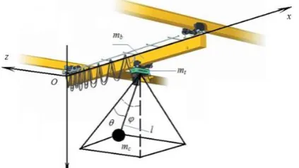
2. SYSTEM DYNAMICS
The physical model of a three dimensional overhead crane can be represented as,
Fig. 1: Physical modeling of overhead crane
[image:1.595.310.522.524.643.2]© 2016, IRJET | Impact Factor value: 4.45 | ISO 9001:2008 Certified Journal
| Page 1421
friction of wipe rope is considered a linear damping elementbr, The frictions of trolley and bridge motions are characterized by bt and bb. The control signal ut, ub and ul denote the driving forces of trolley translation, bridge translation and cargo hoist translational motion.
3. SYSTEM MODELLING
In system modeling Euler-Lagrange formulation is considered in characterizing the dynamic behaviour of the crane system. To derive the dynamic equation of the system, the total energy associated with the crane system needs to be computed using Lagrangian approach.
The Euler equation can be written as,
k k k Q q L q L dt d (1)
The Lagrangian approach can be defined as, the difference between kinetic energy and potential energy of the plant.
L=KE-PE (2)
x l l m z l l l m l m l m l m x m m z m m m L c c c c c c t c b t cos sin sin sin cos cos cos sin 2 1 cos 2 1 2 1 2 1 2 1 2 2 2 2 2 2 2 2(3)
To find Qk in eq.(1), consider the general expression,
k k q Q
(4)
In eq.(1) and (4)k varies as
z x l
, so the derived eq.(4) can be written in 5 different equations.l f rz b z
z
f
b
z
f
d
x
Q
(5) l f rx t x
x
f
b
x
f
d
y
Q
(6)
cos cos sin cos sin cos cos l f l f l f c l l l z d y d x d g m l d f Q
(7)
sin cos cos cos sin cos l z d l x d gl m Q l f l f c (8)
sin cos cos sin sin sin cos l z d l y d l x d gl m Q l f l f l f c (9)
By substituting the equation (3) in LHS of equation (1) and substituting equation (5), (6), (7), (8) and (9) in RHS of eq.(1), The five degree of equation of nonlinear dynamics of the crane system can be written as,b c c c c c b c c c c b t u l m m l m l m l m z b l m l m l m z m m m 2 2 cos sin cos sin sin cos 2 sin sin 2 cos cos 2 sin sin cos cos cos sin ) ( (10) t c c t c c c t u l m l m x b l m l m x m m 2 sin cos 2 cos sin ) (
(11) l c c c r c c c l u g m l m l m l b z m x m l m m cos cos cos cos sin sin ) ( 2 2 2 (12) 0 cos sin sin cos 2 cos 2 cos cos cos 2 2 2 2 gl m l m l l m l m z l m c c c c c (13) 0 sin cos sin cos 2 sin sin cos 2 2 2 gl m l m l l m l m z l m x l m c c c c c c (14)By using the differential equation (10), (11), (12), (13) and (14), the crane system can be modeled.
4. CONTROLLER SCHEME DESIGN
A PID controller and Fuzzy logic controller are proposed to the system. The selection of controller is depends upon the better output performance of the system.
4.1 PID Controller
The first proposed controller is PID controller to move the trolley and the bridge from their initial positions to their destinations as fast as possible, to reduce cargo vibration during transfer, and to eliminate cargo swing at the trolley and bridge destinations.
In the PID controller tuning method, auto tuning method approach is to be achieved. By auto tuning the Kp, Ki
and Kd will be 0.358, 0.572 and 0.746. By the use of PID
controller, the elimination of control problem will be achieved.
4.2 Fuzzy Logic Controller
© 2016, IRJET | Impact Factor value: 4.45 | ISO 9001:2008 Certified Journal
| Page 1422
of five membership functions: negative large, target –desired position, near, medium and large – positive distance. The membership function for deviation in x and φ can be represented as,
Fig.2 : Membership functions for deviation in x and φ,
The position of the payload is described by z and θ. The membership function: negative big, negative little, target, positive medium and positive large can be represented as,
Fig.3 : Membership functions for deviation in z and θ.
An output value from fuzzy controller is voltage and is defined as a linguistic variable as follows: negative big, negative medium, target, positive medium and positive big.
Fig.4 : Output functions from powers of DC motors
The fuzzy logic control is based on six rules, where the first input is distance, the second one is angles position and outputs are powers of DC motors:
The fuzzy logic control is based on six rules, where the first input is distance, the second one is angles position and outputs are powers of the DC motors:
1. If (input1 is negative) and (input2 is target) then (output1 is positive_medium),
2. If (input1 is large_positive) and (input2 is neg._little) then (output1 is positive_big),
3. If (input1 is medium) and (input2 is neg._little) then (output1 is negative_ medium),
4. If (input1 is medium) and (input2 is neg._little) then (output1 is positive_ medium),
5. If (input1 is near) and (input2 is target) then (output1 is positive_medium),
6. If (input1 is target) and (input2 is target) then (output1 is target).
5. SIMULATION& 3D VISUALIZATION
The first step is to evaluate the control problem and selection of controller with respect to the better output performance response.
5.1 Simulation
In this simulation study, the crane plant parameters are set as, Ra=2.6, La=0.012, B==1e-1, Kt=1e-2, Kv=3e-2, Kg=1e-3, J=0.1, m_head=100, Gamma=10 and g=9.806. The initial position of the cart position is x(0).
The major purpose of the simulation is to find the better output performance in the controllers of PID controller and Fuzzy logic controller, and verify the robustness of the system by using the method and its effectiveness for different move distances.
Here, 3 stages of operation will take place, the stages can be written as follows,
1. z - Directional motion and corresponding swing angle φ will operates without cargo load. Other parameters are in rest.
2. z and x – Directional motion and corresponding swing angle φ and θ will operate with cargo load. Here, displacement of cargo load from current position to desired position will takes place.
3. z and x – Directional motion and corresponding swing angle φ and θ will operate without cargo load. Here, the crane set in the initial position.
5.1.1 PID Controller
By using PID controller, the output performance response of the five degree of motion overhead crane system can be represented as,
Fig.5 : Control operation in x-direction
© 2016, IRJET | Impact Factor value: 4.45 | ISO 9001:2008 Certified Journal
| Page 1423
Fig.7 : Controlled swing angle θFig.8 : Controlled swing angle φ
Fig.9 : Controlled hoist motion
Fig.10 : Velocity in x-direction
Fig.11 : Velocity in z-direction
Fig.12 : Cargo swing velocity
Fig.13 : Cargo swing velocity
Fig.14 : cargo hoisting velocity
5.1.2 Fuzzy Logic Controller
By using the fuzzy logic controller, the output performance response of the five degree of motion overhead crane system can be represented as,
Fig.15 : Control operation in x-direction
Fig.16 : Control operation in z-direction
Fig.17 : Controlled swing angle θ
Fig.18 : Controlled swing angle φ
Fig.19 : Controlled hoist motion
Fig.20 : Velocity in x-direction
Fig.21 : Velocity in z-direction
Fig.22 : Cargo swing velocity
Fig.23 : Cargo swing velocity
Fig.24 : cargo hoisting velocity
5.2 3D Visualization
The 3D visualization is the best way of communication of the operating overhead crane system. The three dimensional diagram is designed by using the vrealm software, this software is attached with MATLAB.
Fig.25 : 3D view of overhead crane
© 2016, IRJET | Impact Factor value: 4.45 | ISO 9001:2008 Certified Journal
| Page 1424
movement of the crane. Connect the VR sink block to themodeled system.
While run the simulink model, the 3D operation will be executed. So, the system output performance can be clearly identified.
5.3 COMPARISION
By comparing the performance of the controller in 3 stages of operation,
1. Stage – 1
Controller Swing Angle Time Rise Time Peak Settiling Time Overshoot Peak
PID φ - - - -
θ - 4.7s 16s 0.19
Fuzzy φ - - - -
θ - 4.4s 11.5s 0.16
2. Stage – 2
Controller Swing Angle Time Rise Time Peak Settiling Time Overshoot Peak
PID φ - 23.2s 32.4s 0.18
θ - 23.5s 27.8s 0.18
Fuzzy φ - 19.8s 27.5s 0.149
θ - 18.8s 25.3s 0.145
3. Stage – 3
Controller Swing Angle Time Rise Time Peak Settiling Time Overshoot Peak
PID φ - 38.8s 49.4s 0.185
θ - 41.7s 45.3s 0.143
Fuzzy φ - 38.4s 46.5s 0.165
θ - 37.9s 44.9s 0.136
6. CONCLUSION
In this work, proposed three types of controllers, PID controller and fuzzy logic controller. Here, want to use a better performance controller for the control problem elimination. By comparing the output response of the controller from the simulation results, better output response will generated by the fuzzy logic controller. The fuzzy logic controller was improved the performance in a complicated operation in which cargo lifting, trolley motion and bridge motion by comparing with other controllers. Here, the control problems of the system like swing angle elimination and system stability will be achieved.
REFERENCES
[1] NingSun,Yongchun Fang, XianqingWu, “An enhanced coupling nonlinear control method for bridge cranes” IET Control Theory Appl., 2014, Vol. 8, Iss. 13, pp. 1215– 1223
[2] Karl Johan Astrom, “Control System Design”, chapter – 6, PID Control, 2002
[3] Wahyudi and Jamaludin Jalani, “Design and implementation of fuzzy logic controller for an Intelligent Gantry Crane Sysyem: Robustness Evaluation”, Research Center, International Islamic Wniversity Malaysia, 2007.
[4] Bojun Ma, Yongchun Fang, Xuebo Zhang, Xiaolin Wang, “Modeling and Simulation for a 3D Overhead Crane”, Proceedings of the 7thWorld Congress on Intelligent
Control and AutomationJune 25 - 27, 2008, Chongqing, China.
[5] Omar, H.M, Control of Gantry and Tower Cranes., Ph.D. Thesis, M.S. Virginia Tech, 2003.
[6] Le Anh Tuan, Jae-Jun Kim, Soon-GeulLee,Tae-Gyoon Lim, and Luong Cong Nho, “Second-Order Sliding Mode Control of a 3D Overhead Crane with Uncertain System Parameters” International journal of precision engineering and manufacturing Vol. 15, No. 5, pp. 811-819, May 2014
[7] R.M.T. Raja Ismail, M.A. Ahmad, M.S. Ramli, F.R.M. Rashidi, “Nonlinear Dynamic Modelling and Analysis of a 3-D Overhead Gantry Crane System with System Parameters Variation” IJSSST, Vol. 11, No. 2, pp.9-16 [8] Dianwei Qian1 and Jianqiang Yi, “Design of Combining
Sliding Mode Controller for Overhead Crane Systems” International Journal of Control and Automation Vol. 6, No. 1, February, 2013
[9] Damiano A.,Gatto G.L., Marongiu I., PISANO A. ”Second-order sliding-mode control of DC drives” IEEE Trans. on Industrial Electronics, vol. 51, n. 2, pp. 364-373, 2004. [10] V.I. Utkin “Sliding mode control design principles and
applications to electric drives”, IEEE Transactions on Industrial Electronics, 40, 1, 23.36, 1993.
[11] Hu, G., Makkar, C., Dixon, W.E.: “Energy-based nonlinear control of underactuated Euler–Lagrange systems subject to impacts”, IEEE Trans. Autom. Control, 2007, 52, (9), pp. 1742–1748
[12] Abdel-Rahman, E.M., Nayfeh, A.H., Masoud, Z.N.: “Dynamics and control of cranes: a review”, J. Vib. Control, 2003, 9, (7), pp. 863–908