© 2015, IRJET ISO 9001:2008 Certified Journal Page 313
AREA EFFICIENT IMPLEMENTATION OF ADAPTIVE FIR FILTER BASED
ON DISTRIBUTED ARITHMETIC
LISHA ANNA DANIEL, NIJI MATHEWS
1
Student MTech VLSI and Embedded System, Viswajyothi College of Engineering and Tech., Kerala, India
2
Assistant Professor, Electronics and Communication, Viswajyothi College of Engineering and Tech., Kerala, India
---***---Abstract -
Novel pipelined architectures for low-areaimplementation of adaptive FIR filter based on Distributed Arithmetic (DA) are proposed here. The designs perform parallel lookup table (LUT) update and concurrent implementation of filtering and weight-update operations. The conventional adder-based shift accumulation for DA-based inner-product computation is replaced by conditional signed carry-save accumulation in order to reduce delay and area complexity. The designs use fast bit clock for carry save accumulation but a much slower clock for all other operations. Look Up Table (LUT) size reduction techniques are employed within the filter structures. LUT techniques used include Offset Binary Coding (OBC) and Modified DA Technique, which are employed within the existing structure. Within the OBC technique, LUT structure employed is halved when compared to that of the existing designs. Smaller multiplexor is also used within this structure. Modified DA technique also employs half-sized LUT structure. For the latter technique, the filtering unit employs an additional adder structure but smaller multiplexor when compared with the existing designs. From synthesis results, it is found that the proposed structures are efficient in terms of area from the existing design.
Key Words:
Adaptive Filter, Distributed Arithmetic,
OBC, LMS, DLMS, etc…
1. INTRODUCTION
In the process of transmission of information from the source to the receiver, noise from the surroundings automatically gets added to the signal. The noisy signal contains two components; one carries the information of interest i.e. the useful signal and the other consist of random errors or noise which is superimposed on the useful signal. Therefore the effective removal or reduction of noise in the field of signal processing is an active area of research. There are many schemes for noise removal of which one of the most effective is the use of adaptive filters.
The use of adaptive filter helps in reducing the signal corruption caused by predictable and unpredictable noise. An adaptive filter has the property to self-modify its frequency response to change its behaviour with time. It
allows the filter to adapt to the response as the input signal characteristics change. Due to this capability and flexibility, the adaptive filters have been employed in many different applications like telephonic echo cancellation, radar signal processing etc. Adaptive filters continuously change their impulse response in order to satisfy the given conditions, and by doing so, change the very characteristic of their response. There are certain rules that filters use in order to adapt. These rules or algorithms shall include Least Mean Square (LMS) Algorithm, Normalised Least Mean Square (NLMS) algorithm, Delayed Least Mean Square (DLMS) algorithm etc.
© 2015, IRJET ISO 9001:2008 Certified Journal Page 314
2. Adaptive Filter with Distributed Arithmetic
Theory
This section briefs about Adaptive filter and distributed arithmetic theory.
2.1 Adaptive Filter Configuration
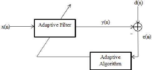
An adaptive filtering environment is illustrated in the figure 1. Here figure shows a block diagram in which a sample from a digital input signal x(n) will be fed into a device, i.e. an adaptive filter, that computes a corresponding output signal sample y(n) at time n. The output signal is compared to a second signal d(n), called the desired response signal, by subtracting the two samples at time n. This difference signal, e(n) is known as the error signal. The error signal is fed into a procedure (filter coefficient update section) that changes the parameters of the filter from time n to time (n + 1) in a well-defined manner. When the time index n is incremented, it is expected that the output of the adaptive filter becomes a better match to the desired response signal through this adaptation process, such that the magnitude of e(n) decreases over time[2].
Fig -1: General Adaptive Filter Configuration
2.2 LMS Algorithm
The Least Mean Square (LMS) algorithm, introduced by Widrow and Hoff in 1959 is an adaptive algorithm, which uses a gradient-based method of steepest decent. It mainly consist of two basic processes namely a filtering process, which computes the output of a linear filter in response to an input signal and generates an estimation error by comparing this output with a desired response. Secondly it performs an adaptive process, which adjusts the parameters of the filter in accordance with the estimation error.
With each iteration of the LMS algorithm, the filter tap weights are updated according to the following formula given as:
W(n+1) = W(n)+µ · e(n) · x(n) (1) e(n) = d(n) – y(n) (2)
y(n) = x(n) · WT(n) (3)
where the input vector is x(n), µ is the learning rate parameter or step size, y(n) is the filter output, d(n) is the desired input and the weight vector is given by W(n) for ‘n’ iterations. Here µ controls the stability and convergence speed of the LMS algorithm.
2.3 Distributed Arithmetic
DA is a bit serial operation used to compute the inner (dot) product of a constant coefficient vector and a variable input vector in a single direct step [3] and is given by
(4)
Here wk are fixed coefficients and xk are inputs. If each wk
is a 2's-complement binary number scaled such that |wk|<1 then each wk can be presented as
(5) Where wkl denotes the lth bit of wk.
Combining equations (4) and (5), output y obtained as per distributed arithmetic computation is as below
(6)
Where ‘L’ is the bit width and ‘N’ is the filter length.
3. Related Work
Existing DA based LMS filter proposed by P. K. Meher and S. Y. Park in [1] included two main sections i.e. the Weight increment block and the N-Point inner product block. The structure of DA-based adaptive filter of filter length N = 4 is shown in figure 2. The noisy input signal x(n) of ‘L’ bits, along with the filter coefficients each of ‘L’ bits are provided to the inner product block serving as the filtering unit. The filtering unit produces the filter output y(n). The error output e(n) is computed by subtracting y(n) from desired signal d(n). The product of convergence factor µ, input signal x(n) and error e(n) are provided to the weight increment block where new filter coefficients are generated in each iteration. This process continues until the error output e(n) converges to the noise free original signal.
[image:2.595.42.286.408.521.2]© 2015, IRJET ISO 9001:2008 Certified Journal Page 315 Fig -2: DA Based LMS Filter with N = 4
3.1. Four Point Inner Product Block
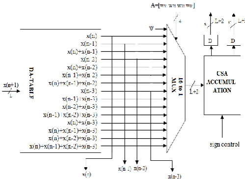
The four point inner product block consists of the distributed arithmetic table that computes the inner product, a 16:1 mux and a carry save accumulation section. As shown in figure 3 below, the DA table outputs are computed. Then the results are provided to a 16:1 mux to select the inner product combination outputs based on the bit slices of the weight bits provided as select line to the multiplexor.
Fig -3: Four Point Inner Product Block with DA
The output of the mux is fed to the carry save accumulator (CSA). After ‘L’ bit cycles, the carry save accumulator shift accumulates all the partial inner products and generates a sum word and a carry word of size ‘L+2’ bits each. The sign control bit is used to generate 1s complement output of the sum and carry. This bit is 1 when the MSB weight bits arrive and is 0 for the remaining bits. The carry and sum words are shifted added with an input carry ‘1’ to generate
filter output y(n) as in figure 2. 2s complement output y(n) is resulted here. Here within the block, carry propagate adders are used for the computation of partial inner products. Thus delay can be reduced than when ripple carry adders are used. The error output computation is done by subtracting the filter output from the desired signal d(n). Since y(n) is a 2s complement result, a carry propagate adder is used for obtaining error output.
3.2. Sign Magnitude Separator and Control Word
Generator
For weight update operation, error is to be multiplied with input signal. The sign magnitude separator separates the sign (MSB) and magnitude (remaining bits) of error. Multiplication of input xn by error is implemented by right
shift through the number of locations given by the number of leading zeroes in the magnitude of error. The magnitude of the computed error is decoded to generate the control word‘t’ for the barrel shifter.
3.3. Weight Increment Block
Weight Increment block consists of four barrel shifters and four adder/subtractor cells. The convergence factor µ = 1/N. In case of four point inner product block, N = 4. Thus µ = 1/4 i.e. µ = 1/22 = 2-2. Thus right shifting error
output by 2 will give the result µ·e(n-2). The magnitude obtained from µ·e(n-2) can be used for the control word generation ‘t’ of the barrel shifter shifts the different input values xn for n = 0,1,...,N−1 by appropriate number of
locations. The sign bit of the error is used as the control for adder/subtractor cells such that, when sign bit is zero or one, the barrel-shifter output is respectively added with or subtracted from the content of the corresponding current value in the weight register. Hence the new weights are obtained.
4. Proposed DA Based Implementation
In this paper, LUT size reduction techniques are employed within the DA section used in the inner product block of the existing structure. The main aim is to perform area reduction. Filter structures of filter length N=4 and 16 are implemented as mentioned in [1].
4.1 Offset Binary Coding Distributed Arithmetic
Offset Binary Coding also known as Excess K,is a digital coding scheme where all-zero corresponds to the minimal negative value and all one to the maximal positive value. OBC techniques can be applied in DSP [3]. Offset binary coding can reduce the LUT size by a factor from 2 to 2N-1
[image:3.595.40.290.454.636.2]© 2015, IRJET ISO 9001:2008 Certified Journal Page 316 Suppose that one can assume wk as
(7)
and also in 2's-complement notation the negative of wk is
written as
(8)
Where the over score symbol indicates the complement of a bit. Here indicates the lth bit of Here is of ‘L’
bits width. From equations (7) and (8), one can write
(9)
In order to simplify the notation later, it is convenient to define the new variables as
(10)
where n≠0 and
(11)
Now equation (9) can be written as follows (12)
By substituting equation (12) in (6), the following result is obtained
(13)
(14)
Where (15)
and (16)
Based on the above equations, the filter structure has been implemented. Here OBC is employed to reduce the LUT size by half. The figure 4 shows the proposed inner product block (for filter length N = 4) used to replace the existing one for the purpose of area reduction.
Fig -4: Four Point Inner Product Block with OBC-DA
In the figure 4, the weight bit w3l is xor-ed with the weight
bits {w2lw1lw0l} where 0<=l<=L-1. The result obtained can
be used to select the LUT content. The weight bits for each coefficient arrive in LSB to MSB order. OBC technique is employed as in [4] for the computation of partial inner products used within the DA table. The Sign Control bit helps in the computation of one’s complement of the filter output. As the LSB weight bits arrive, an extra term Q(0) called the mid-value is also added to the LUT output. The mid-value for OBC technique is calculated as per the equation (16) i.e.
Q(0)=½(x(n)+x(n-1)+x(n-2)+x(n-3)) (16)
Thus for the LSB weight bits, within the carry save accumulator, the mid-value is added with the LUT output. For the remaining bits, normal carry save accumulation occurs. Thus the filter output can be computed and the result is given to the weight update section for further computation and so on. Hence the LUT size is reduced to half and thus area utilization is reduced here.
4.2 Modified DA Technique
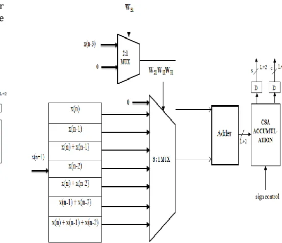
LUT size can also be reduced to half by Modified DA technique. Consider DA Table of figure 3 of the existing structure. One can observe that the lower half of the LUT is the the sum of the upper half of LUT contents and x(n-3). Hence, LUT size can be reduced to 1/2 with an additional 2x1 multiplexer and a full adder, as shown in figure 5 (for filter length N=4). The DA table for the technique mentioned is shown within the figure.
[image:4.595.283.560.482.720.2] [image:4.595.52.486.532.738.2]© 2015, IRJET ISO 9001:2008 Certified Journal Page 317 The working of the proposed four point inner product
block can be summarized as below. The three weight bits {w2lw1lw0l } are used to choose the LUT output. Based on
the weight bit w3l, x(n-3) may be added or not added along
with the LUT output. Here if the weight bit w3l is a ‘1’, then
x(n-3) is added with the LUT output else not. The sign control bit is zero for the LSB weight bits arriving. When the MSB weight bits arrive, the sign control bit will be one. Thus one’s complement filter output is obtained by this technique again. The LUT output is provided to the carry save adder section to produce the sum and carry results similar to the existing structure.
5. Synthesis Results
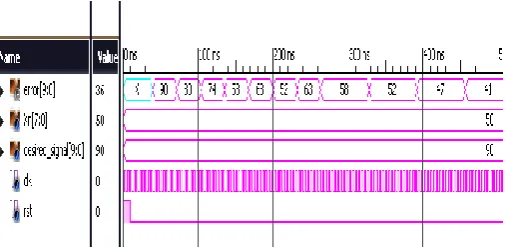
Existing and proposed structures are simulated and implemented using Xilinx for filter lengths N = 4 and 16. Simulation result of Modified DA based Adaptive filter for N = 4 is shown in figure 6.
Fig -6: Adaptive Filter Output with Modified DA
Here in figure 6, the input ‘Xn’ (noise input) = 50 and the Desired signal ‘desired_signal’= 90. Error output ‘error’ is converging towards the value original signal value i.e. 40. Similar results are obtained for filter structure employing OBC-DA. Charts 1 and 2 show comparisons of the implemented structures in terms of area.
Chart -1: Area comparison for N = 4
Chart -2:Area comparison for N = 16
[image:5.595.310.558.102.268.2]Thus from the comparison charts, it is clear that the proposed structures are efficient in terms of area from the existing structures. Table 1 shows the area utilization as per the synthesis results in Xilinx.
Table -1: Number of Occupied Slices for N = 4 and 16
Existing DA Filter Structure
OBC-DA Filter Structure
Modified DA Filter Structure
N = 4 270 224 212
N =16 1241 1068 1029
6. CONCLUSIONS
Efficient pipelined architectures for less area implementations of DA-based adaptive filter are proposed and implemented. A carry-save accumulation scheme of signed partial inner products for the computation of filter output is used here to reduce the delay. Here LUT size reduction techniques are employed. On comparing the filter structures developed, in terms of area, one can conclude that the existing structures consume maximum area when compared to the proposed structures. As future modification, the LUT size can again be reduced to 4 word ROM using OBC DA and Modified DA technique [5].
REFERENCES
[1] Sang Yoon Park, Pramod Kumar Meher, “Low-Power, High- throughput, and Low Area Adaptive FIR Filter Based on Distributed Arithmetic”, IEEE Transcantions on Circuits and Systems-II:Express Briefs,Vol.60,No.6,June 2013.
[2] Douglas, S.C. “Introduction to Adaptive Filters”, 1999
[image:5.595.38.291.337.462.2]© 2015, IRJET ISO 9001:2008 Certified Journal Page 318 review,” IEEE ASSP Mag., vol. 6, no. 3, pp. 4–19,
Jul. 1989.
[4] R. Guo and L. S. DeBrunner, “A novel adaptive filter implementation scheme using distributed arithmetic,” in Proc. Asilomar Conf. Signals, Syst., Comput., Nov. 2011, pp. 160–164.