© 2015, IRJET ISO 9001:2008 Certified Journal Page
178
Object Recognition using Template matching with the help of Features
extraction method
Amanpreet Kaur
1, Er. Priyanka Jarial
21
Research Scholar, Computer Engineering, UCoE, Punjabi University, Patiala, India
2
Assitant Professors
, Computer Engineering, UCoE, Punjabi University, Patiala, India
---***---Abstract -
: In this paper feature extraction method isused for recognition of particular object from group of objects. Template matching approach is used to create a template with the help of which identification of object is possible. Template is mainly a sub-part of an object which is to be matched among different objects. Initially feature set is maintained which is useful in case of matching. It mainly contains feature points. These are points which are sufficient to describe the structure of an object. These points are mainly extracted features of an object. We have to extract the features of following: 1) Features of source image with which matching has to be performed. 2) Features of database images from which we have to find matched objects. In this paper SURF features extraction method is used. After extracting features matching has to be performed.
Key Words:
Recognition, feature detection, feature
extraction, SURF, Template matching.
1. INTRODUCTION
All around us are real world objects. Recognition of object is mainly a process of identifying particular object or needed objects from multitude of objects in single image. We have to classify these objects which are visible to us. These objects may be completely visible or partly hidden behind another object. Similar objects may also be present in different pose. The identification of these objects is easy for human being because he can easily detect any object based on his knowledge or experience but it is much difficult to detect a particular object for a machine. Machine has to learn how to identify any object. For this problem certain algorithms are proposed. With the help of these algorithms a machine can recognize objects present in different pose, lightning conditions, camera parameters, appearance etc. Objects having different appearance may not be different. For example, writing style of different people is different. Two persons can write single letter with different styles.
In this paper for the recognition of an object first of all the image should be converted into gray color image if it is colored image and then SURF features detection is used. It is Speeded up Robust Features. It is both detector and
descriptor of local features which is helpful in detecting required features. It uses square-shaped filters to detect interested points. After detecting these points next step is detecting its neighbor points and the last thing is matching. After detection, the next step is extraction of those features. Instead of block matching, feature matching method is adopted because it is fast matching method and provides good accuracy. Extracted features are maintained in a set which is called feature set or sometimes it is called feature vector. It is mainly a collection of points which are useful in description of structure of a given object. It can be collection of lines or curves instead of points. These elements which are present in feature set are those points which are non-repeating as well as informative. This set is initial step for feature extraction and helpful in dimension reduction. At the end matching is taken place which works on the basis of ‘Brute-Force’ algorithm. By template matching a template is created which can be part of image containing that object which we want to identify in given database.
2.
PROCESS OF RECOGNISING
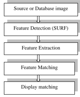
[image:1.595.416.570.543.730.2]The whole work is done in following steps which is shown in flowchart given blow.
Fig 2.1 - Flowchart of recognition of objects. Source or Database image
Display matching Feature Detection (SURF)
Feature Extraction
© 2015, IRJET ISO 9001:2008 Certified Journal Page
179
Initially we should maintain a database which can havenumber of images. After that select a source image. This all comes under requirement gathering phase.
Next step in process is detection of features. This is done with the help of SURF detection. By this only those features are detected which contains important information and are sufficient to describe details of an object i.e. the structure of an object. Then create a feature vector or feature set with the help of extraction phase. It is mainly a set which contains only necessary points. Feature set is created for source image and also for all images present in database. Each image has its separate feature set. After that matching has to be performed. During this phase the feature set of source image or query image is compared with feature set of each and every image present in database and those images are declared as matched images whose feature set points are matched otherwise they are not matched.
3.
DIFFICULTIES DURING RECOGNISING
There are several difficulties which are to be handled during identifying object. These problems can hamper the process of detection or recognition. Some of these problems are given as under:
The main complexity during recognition is view point or lightning conditions. Here are some other conditions like camera parameters, object background etc.
Another factor is rotation i.e. object may be visible in any rotated form. It may be present in straight position or at some angle.
Similar object may be present in different pose or may have different appearance like in case of handwriting different people write same letter in different style.
Sometimes there may be problem of mirroring of objects.
If number of objects is large then there can be difficulty in finding required object or we can say that it will consume more time to find object in large numbers of objects in single image.
The most serious problem is occlusion. By occlusion we mean absence of required features of an object. In case of number of objects in given image sometimes required object hides behind another object(s). In that case some of features are not able to be extracted.
4. PARAMETERS USED IN IMPLEMENTATION
Sensitivity: it mainly finds value for total images matched correctly.
Specificity: it provides value for total images not matched.
Positive prediction value: by this we mean the value for our positive prediction and also the result is positive.
Negative prediction value: this parameter gives us value for our positive prediction having negative result.
Recognition rate: it provides value of total truly matched images from total images of database.
Accuracy: it is the total matching percentage of images of database.
5. EXPERIMENTAL RESULTS
Now under this part the result of implementation is described. Before discussing the result, the important part of work is needed to explain i.e. creating GUIDE. With the help of guide GUI is created or we can edit it if already created. It is needed to create a GUIDE because it is able to handle two different kinds of files which are .m files and .fig files where .fig files includes all figures and .m file handles the whole coding.
After completing all the phases provided in process in recognition (II), the output is derived. First of all the path for database directory is chosen which will select the database folder. After that the path for source image is provided. The output contains two images, one after another with the help of montage display method. The first image is the source image and the second image is matching among that source image and database images. That matching is displayed with the help of line joining the matched features among both images. It also shows total number of images in database and number of images matched with source image and also number not matched images. Beside these two images, two tables are also shown in output. The first table is matching table which contains all pair of feature points which are matched among the query image and database image. The second table is match metric table which show the value of those pairs of feature points which are matched.
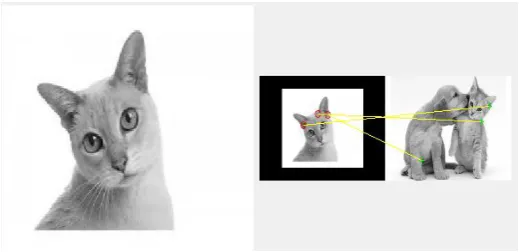
[image:2.595.308.568.607.733.2]Here a fig. 5.1 shows source image and matching among that image and database image.
© 2015, IRJET ISO 9001:2008 Certified Journal Page
180
In above figure, it is clearly shown that the image presentat left side is source image whereas the image shown in right side is source image as well as database image (which can have any number of objects ) and identification of source object in that database image. The matching is clearly shown with the help of line joining between both images.
[image:3.595.306.569.69.281.2]Now the next part of implementation is tables.
Table 5.1- Matching feature pairs
These are tables which show coordinates of those pairs which are matched and also the value of those matched pairs. In above table 5.1, it is clearly shown that in fig. 5.1 there is three pair of feature points which are matched because there are three lines joining those images. Those three pairs are shown in table of matching feature pairs. The value of both coordinates is given in table 5.1 i.e. in pair (3, 12), the value of x-axis is 3 and value of y-axis is 12.
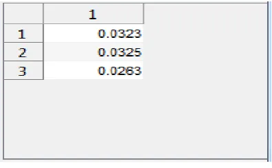
Table 5.2- Match metric table
In table 5.2, the values for those matched pairs are shown. For example the value for pair (3, 12) is 0.0323; the value for pair (21, 72) is 0.0325. Similarly the value for feature point pair (29, 48) is 0.0263.
[image:3.595.37.261.216.328.2]Now the whole implementation is shown in fig. 5.2. After selecting path for database as well as for source object image, the matching process begins. In this figure it has been shown that there were total five images in database and all of them are matched.
Fig. 5.2- Matching with object image
Here is another database with has 21 images included in it and among those 20 are matched and 1 is not matched. It has been shown in fig 5.3.
Fig. 5.3- Another example of matching
Along with two images, two tables are shown which display matching pair of feature points as well as the value corresponding to those points.
Here is a table which shows that there are total of eight databases provided in table 5.3 and value for different parameters is also provided. These values are derived from the work done during recognizing different source objects in different databases having different number of images present in them.
DB Sens Spec PPV NPV RR
DB1 0 0 0 0 0
[image:3.595.312.568.359.531.2] [image:3.595.36.234.480.602.2]© 2015, IRJET ISO 9001:2008 Certified Journal Page
181
DB3 0.9583 0.5000 0.9200 0.6667 0.9200
DB4 1 0.8000 0.8333 1 0..8333
DB5 0.6250 0 0.8333 0 0.5555
DB6 0.9444 0 0.8500 0 0.8095
DB6 1 0 1 0 1
[image:4.595.216.536.51.269.2]DB8 0 1 0 1 0
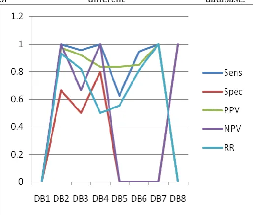
Table 5.3 Comparison of different parameters
Based on parameters used in implementation, i.e. sensitivity, specificity, positive prediction value, negative prediction value and recognition rate, the graph has shown displaying different values for different parameter
of different database.
Fig. 5.4 Comparing different parameters
Eight databases are provided to compare these parameters. The graph is shown in fig. 5.4. Different colors are used to represent different parameters
Graphical Representation of Matching Process:
In fig. 4.2, the graphical representation of matching process is provided. It is shown that both parameters are directly proportional to each other.
If number of images is large in database, the total time taken to process all images is also increased.
Fig. 5.5 Graphical representation
If number of images is large in database, the total time taken to process all images is also increased.
6. CONCLUSION
In this paper template matching approach is followed. After requirement gathering i.e. collection of database images and selection of query image, detection of features is taken place with the help of SURF detection method. It is helpful in detection of beneficial point. It is also a descriptor which describes local neighbor points. The next step is extraction of those features and creates a feature step which has non repeatable and valid points. It is also useful in dimension reduction of complex images. At last the matching among source image and database image is taken place and it is done with the help of template matching which creates a template and search that template in all images of database. If template is matched in any database image that it is declared as matched image otherwise not matched image.
REFERENCES
[1] Adegoke, B.O1, Ola, B.O. 2 and Omotayo, M.E3, “Review of Feature Selection Methods in Medical Image Processing”, IOSR Journal of Engineering (IOSRJEN), January 2014.
[2] Xiang Sean Zhou, Ira Cohen, Qi Tian, Thomas S. Huang , “Feature Extraction and Selection for Image Retrieval”, Beckman Institute for Advanced Science and Technology University of Illinois at Urbana Champaign, Urbana.
[image:4.595.37.295.330.549.2]© 2015, IRJET ISO 9001:2008 Certified Journal Page
182
[4] Ge Liu, Xian Sun, Kun Fu, and Hongqi Wang “AircraftRecognition in High-Resolution Satellite Images Using Coarse-to-Fine Shape Prior”, IEEE Geo science and remote sensing letters, May 2013.
[5] Zhangzhang Si and Song-Chun Zhu, Fellow, IEEE “Learning AND-OR Templates for Object Recognition and Detection”, IEEE transactions on pattern analysis and machine intelligence, vol. 35, no. 9, September 2013.
[6] Paolo Barsocchi,“ Position Recognition to Support Bedsores Prevention”, IEEE journal of biomedical and health informatics, January 2013.
[7]SHAKERI Moein, ZHANG Hong “Object Detection Using a Moving Camera under Sudden Illumination Change”, Proceedings of 32nd Chinese Control Conference, July 26-28, 2013.
[8] Song Qing-kun Yuan Hui-jun Zhou Teng “License Plate Recognition Based on Mathematical Morphology Method and RBF Neural Network”, 1ntemational Conference on Measurement, Information and Control (M1C), 2012.
[9] Faizan Ahmad, Aaima Najam and Zeeshan Ahmed “Image-based Face Detection and Recognition”, IJCSI International Journal of Computer Science Issues, November 2012.
[10]A. Shokoufandeh, Y. Keselman, M.F. Demirci, D. Macrini, S. Dickinson, “Many-to-many feature matching in object recognition: a review of three approaches”, IET Computer Vision, July 2012.
[11] Inad A. Aljarrah, Ahmed S. Ghorab, Ismail M. Khater, “Object Recognition System using Template Matching based on Signature and Principle Component Analysis”, International Journal of Digital Information and Wireless Communications (IJDIWC), 2012.
[12] S. Fidler, M. Boben and A. Leonardis, “A Course-to-fine taxonomy of Constellations for Fast Multi-class object detection”, Proc. 11th European Conference Computer Vision, 2010.
[13] He W., Zhao X., Zhang L., “Online Feature Extraction and Selection for Object Tracking, Mechatronics and Automation” Proceedings of the 2007 IEEE International Conference on Mechatronics and Automation, CMA 2007, pp.3497-3502, (2007).
[14] K. Mikolajczyk and C. Schmid, “A performance evaluation of local descriptor”, IEEE Transactions on Pattern Analysis and Machine Intelligence, 2005.
[15] Pedro F. Felzenszwalb, Daniel P. Huttenlocher, “Pictorial Structures for Object Recognition”, Computer Vision, vol. 61, 2005
[16]W. Zhao, R. Chellappa, P. J. Phillips and a. Rosenfeld “Face Recognition: A Literature Survey”, ACM Computing Surveys, Vol. 35, No. 4, December 2003.
[17] Serge Belongie, Jitendra Malik and Jan Puzicha, “Shape matching and object recognition using Shape contexts” IEEE Transactions on pattern analysis and machine intelligence, April 2002
[18] Y. Boykov, O. Veksler, and R. Zabih, “ Fast approximate energy minimization via graph cuts”, IEEE
Transactions on Pattern Analysis and Machine
Intelligence, November 2001.
[19] M. Reinhold, D. Paulus and H. Niemann, “Appearance based Statistical object recognition by Heterogeneous background and occlusions”,Proc. of the 23rd DAGM Symp. of Pattern Recognition, 2001.