© 2016, IRJET | Impact Factor value: 4.45 | ISO 9001:2008 Certified Journal
| Page 2645
Clustering Routing Protocol for Energy Efficiency of Wireless Sensor
Network using Genetic Algorithm
Gaurav Sudhir Deshmukh
1, Dr. V. D. Khairnar
2, Prof. Sujata Kadu
31
Student, Dept. of Information Technology, Terna Engineering College, Navi Mumbai, Maharashtra, India
2Professor, Dept. of Information Technology, Terna Engineering College, Navi Mumbai, India
3
Professor, Dept. of Information Technology, Terna Engineering College, Navi Mumbai, India
---***---Abstract -
Wireless Sensor Network has been used in variousfields of work. Wireless Sensor Network(WSN) consist of large number of wireless nodes called as sensor nodes and one or more base stations called as sink. The main function of sensor nodes in every wireless sensor network is sensing the target area and sending the gathered data to the sink node for further use. Sensor nodes in the big wireless sensor networks are generally powered by small and low energy batteries, which are not sure for surviving a long period [2]. Thus the main constraint in designing a clustering routing protocol in WSNs is less power of the sensor nodes, which directs the design of energy efficient clustering routing protocol. In the proposed system, a clustering routing protocol is designed for energy efficiency and load balancing of the wireless sensor network. The proposed system uses genetic algorithm for energy efficient clustering of sensor nodes and selection of optimal path for routing with better network lifetime and lesser energy consumption. It also shows how energy efficiency can be increased if we make the sink mobile.
Key Words: Wireless Sensor Network (WSN), Low
Energy Adaptive Clustering Hierarchy (LEACH), Low Energy Adaptive Clustering Hierarchy- Simulated Annealing and Genetic Algorithm (LEACH-SAGA), Mobile Sink Load Balancing- Low Energy Adaptive Clustering Hierarchy (ML-LEACH)
1. INTRODUCTION
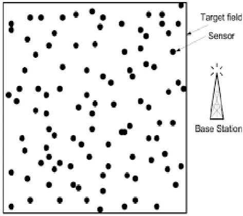
The sensor nodes used in wireless sensor network collect information from the environment based on their sensing mechanism. The nodes are arranged in large numbers in the area. All the nodes together form an ad hoc network which can send data to the sink (base station). A sample Wireless Sensor Network is shown in figure-1. Wireless sensor network have many applications in Agriculture, health care systems, military surveillance, Anti fire systems, etc.
The sensor node must have capability to collect the data and send that data to other nodes or directly to an external
sink which may be fixed or mobile [2].
[image:1.595.333.570.376.587.2]Resource constraint of the sensor nodes and weak low-power wireless links, along with various performance requirements of different applications generates many challenges in designing energy efficient communication protocols for wireless sensor network. So, designing suitable energy efficient clustering routing protocol to increase the lifetime of the wireless sensor network is considered as an important issue in wireless sensor networking.
Figure -1: A sample Wireless Sensor Network
© 2016, IRJET | Impact Factor value: 4.45 | ISO 9001:2008 Certified Journal
| Page 2646
over the clusters.As size of the sensor network increases, distribution of the networking load effectively will be an important concern. By spreading the workload across the cluster in sensor network that is by load balancing we can average the energy consumption. Load balancing is also useful for reducing energy-hole problem, and thus increasing the reliability of the data and network.
Therefore, the proposed system tries to address the challenge of balancing energy consumption and maximizing the network lifetime for WSNs by developing the energy efficient clustering routing protocol using genetic algorithm and mobile sink.
2. RELATED WORK
Wireless sensor networks have been more extensively considered for research and use in different fields. Many clustering algorithms in different contexts have been proposed in the past by [4, 5, and 6]. Many of these algorithms aim at minimizing the energy spent in the homogeneous system.
Mhatre and Rosenberg (2004) [7] give guidelines about the modes of propagation, clustering and battery energy of normal and CH nodes. Cheng and Shi (2009) [8] analyzed the heterogeneity with new clustering algorithm, which decides the cluster head according to the node energy.
Hur and Kim (2008) [9] explains about adaptive clustering and power control for homogeneous sensor networks. A survey on energy saving mechanisms for WSN is given by [10] (Wang and Xiao, 2005).
As there is no centralized cluster formation mechanism in ‘Power Efficient Gathering in Sensor Information Systems (PEGASIS)’ [11], thus each node has to spend additional energy for performing data aggregation to achieve hierarchical distribution of energy. In [12], Chan et al. proposed An Emergent Algorithm for Highly Uniform Cluster Formation. In [13], Chen et al. proposed Energy Efficient Clustering Scheme in Wireless Sensor Networks. In [14], Hong-Yen et al. proposed an Axis-based virtual coordinate assignment protocol and delivery-guaranteed routing protocol in wireless sensor networks.
In [15], Mohamed et al. proposed a uniform energy balancing routing protocol for wireless sensor networks. Lu et al. in [16] proposed an Energy-Efficient Multi-path Routing Protocol (EEMRP); it has the capability of searching multiple node-disjoint paths and utilizes a load balancing method to assign the traffic over each selected path. Both the residual energy level of nodes and the number of hops are considered to be incorporated into the link cost function. It uses a
fairness index to evaluate the level of load balancing over different multi-paths. Furthermore, since EEMRP only takes care of data transfer delay, sometimes reliability of the successful paths is limited.
3. MOBILE SINK LOAD BALANCING- LOW
ENERGY
ADAPTIVE
CLUSTERING
HIERARCHY PROTOCOL (ML-LEACH)
3.1 Low Energy Adaptive Clustering Hierarchy
Protocol (LEACH)
LEACH protocol is a routing protocol in wireless sensor networks. It selects some nodes as cluster heads (CH). Other ordinary sensor nodes send data to the cluster head. Cluster head fuses the data sent by the ordinary nodes and then send it to the sink, thus it reduces the cost of redundant data transmission. The LEACH protocol consists of two stages namely setup phase and ready phase. A round means the total time of setup phase and ready phase. In the setup phase, clusters are formed and cluster heads are selected. In the ready phase, ordinary nodes send the sensed data to the cluster head; further cluster head sends integrated data to the sink. Cluster head uses TDMA to allocate time slots to each node to send data. Cluster heads also use CDMA encoding mode for communication to avoid conflicting with other cluster nodes.
3.1.1
The disadvantages of LEACH protocol
LEACH protocol considers the cost of communication between the ordinary node and cluster head; it does not consider the remaining energy of cluster head and its current location information. Probability of a node to become a cluster head is roughly same in each round regardless of the remaining energy of the node. If node with lower residual energy is selected as a cluster head, it may get dead in short time resulting in some area in monitoring region appearing blind, thus reducing the robustness of the network.
© 2016, IRJET | Impact Factor value: 4.45 | ISO 9001:2008 Certified Journal
| Page 2647
3.2 Low Energy Adaptive Clustering Hierarchy-
Simulated Annealing and Genetic Algorithm
(LEACH-SAGA)
LEACH-SAGA protocol selects the cluster heads using simulated annealing and genetic algorithm. Sink has continuous supply of the energy. The clustering is done in two phases: setup phase and ready phase. In the setup phase, clustering of randomly deployed sensor nodes is done using simulated annealing and genetic algorithm. At the time of selection of cluster heads, residual energy of the sensor node and the average energy of the cluster are considered, the sensor node having residual energy greater than the average energy of the network and which is near to the cluster center is selected as cluster head. In the ready phase, the ordinary sensor nodes send the sensed data to the cluster head and further cluster head sends the integrated data to the sink through one hop or multi-hop mode of communication.
The simulated annealing algorithm depends on the physical process of metallurgical annealing [17]. Initial solution is evaluated, and then new candidate solution with small modification is evaluated. If the new solution is better than the previous solution, it is accepted and assumed as current solution, in other case if new solution is not better than the last solution, it can accept the new worst solution with certain probability.
3.2.1
The disadvantages of
LEACH-SAGA protocol
Sink in the LEACH-SAGA is static. Sink is generally positioned at the geographical center of the wireless sensor network area. If density of cluster heads is more at some corner of the target area and less in the rest of the target area, in this case communication cost increases due to large distance between sink and those cluster heads in the area of more density. This increased communication cost can be reduced by moving the sink to the area where density of cluster heads is more and thereby reducing the cost of communication between cluster heads and the sink. So, new clustering routing protocol with this concept is designed in proposed system.
3.3
Mobile Sink Load Balancing - Low Energy
Adaptive Clustering Hierarchy Protocol
(ML-LEACH)
ML-LEACH protocol uses genetic algorithm in combination with simulated annealing for cluster formation and selection of cluster heads. The clustering is done in two phases: setup phase and ready phase. In the setup phase, clustering of randomly deployed sensor nodes is done using genetic algorithm in combination with simulated annealing. By considering residual energy of the sensor node, the average energy of the network and distance of the node from center of the cluster, cluster heads are selected. The sensor node
having residual energy greater than the average energy of the network and which is nearer to the cluster center is selected as cluster head. Sink is moved to area where density of cluster heads is more so as to reduce the communication cost between a cluster head and sink, thereby increasing the energy efficiency of the network, which in turn increases the life time of the network. In the ready phase, the ordinary sensor nodes send the sensed data to the cluster head and further cluster head sends the integrated data to the sink.
3.3.1 Cluster formation process
The genetic algorithm is an effective search algorithm that can simulate the adaptive evolution process of natural systems; it can be applied to many similar problems in the field of wireless sensor network. Each individual in the population of genetic algorithm represents a possible solution to the problem.
Finding best individual to the problem is the ultimate aim of the genetic algorithm. Different elements of Genetic Algorithm are:
3.3.1.1Selection
Individuals are selected according to some fitness standards also called as fitness value.
3.3.1.2 Crossover
It is one way of breeding. Here best individuals are combined to form a new individual. It is an important stage of evolution process.
3.3.1.3 Mutation
In Mutation, new genetic patterns can be introduced in the new chromosomes. Mutation inserts new patterns of genes into a chromosome. But it is not guaranteed that there will be desirable features in the new chromosome after the mutation.
By applying the above operations repeatedly, population will evolve into best individuals.
Flowchart shown in the figure-3.1 shows the flow of operations for clustering process.
3.3.2 Cluster Head selection
© 2016, IRJET | Impact Factor value: 4.45 | ISO 9001:2008 Certified Journal
| Page 2648
where cluster head collects data from the normal nodes andsend this integrated data to the sink, energy of the cluster head is significantly reduced. In the second round again the new cluster head will be selected using the above process. Thus, cluster head role will be circulated among the eligible members of cluster and thus increasing the first dead node time, resulting in maximizing the life time of the network.
Flowchart shown in the figure-3.2 shows the cluster head selection process.
Figure-3.1: Cluster formation process using genetic algorithm and simulated annealing [18]
3.3.3 Sink Positioning
The main objective of the proposed protocol is the minimization of overall energy required in the wireless sensor network. Sink location is one of the important factors in wireless sensor network. Generally sink is positioned at the geographical center of the wireless sensor network area. As cluster head role is rotating among the cluster members, cluster head location gets changed. If density of cluster heads is more at some corner of the total area, then geographical center as location for sink is not good, as when each cluster head communicates with sink, energy consumption is increased due to large distance between cluster heads and sink. If we move the sink near to the area, where density of cluster heads is more, communication cost can be reduced. So in the proposed protocol, we place the sink at centroid of the distributed cluster heads and we can see communication
cost gets reduced. When location of cluster heads gets changed, centroid also gets changed, thus changing the location of the sink, resulting in reducing the communication cost. Coordinates of the sink location C(X, Y) can be found using following equations:
X (3.3.3.1)
Y (3.3.3.2)
In the above equations, n is total number of cluster heads. Flow chart in the Figure-3.3 shows process for deciding location of mobile sink.
Figure-3.2: Cluster head selection process No
Yes
Yes
No
No
Yes
No
Yes START
Initial Population Generation
Calculate membership Degree & Fitness value for
each Individual
Count=0
Selection Operation
Crossover Operation
Mutation Operation
New Population
Calculate Cluster Center
If new fitness value > Old
fitness value
Accept new individual; Count = Count+1
Count=Count+1
If Count < TotalGens
Final Solution
Accept new individual with probability P; Count=Count+1
START
Calculate Average Energy of cluster, distance of each node from cluster centre
Energy of node >Average energy of cluster
Node is nearest to the cluster center
Node becomes member of candidate cluster head set
The node is selected as cluster head
Node is rejected
STOP
Node is not eligible
© 2016, IRJET | Impact Factor value: 4.45 | ISO 9001:2008 Certified Journal
| Page 2649
Figure-3.3: Process of finding the location of sinkIn case of large number of cluster heads and large wireless sensor network area, we can assign weights to cluster heads according to their distance from the centroid, and use those weights for finding the more optimized location for sink.
4.
RESULT ANALYSIS
4.1 Experiment Setting
We compare the LEACH protocol, LEACH-SAGA protocol and the proposed ML-LEACH protocol in MATLAB.
Experiment settings required are:
(1) All the sensor nodes are randomly deployed in the area. In this experiment we are using 300 sensor nodes.
(2)Sink is located at centroid of cluster head locations. The sink location is dynamic as centroid gets changed with changing location of cluster heads.
(3) Energy of all the nodes is same initially.
(4) ID and location of each node is known to the base station.
The number of clusters formed is 9. Here we have used packet size as 5000bits.Total numbers of generations in the genetic algorithm are 50. Population size is 10. We have considered crossover probability and mutation probability as 0.7 and 0.01 respectively.
4.2 Experimental Result Analysis
We compare LEACH protocol, LEACH-SAGA protocol and the proposed ML-LEACH protocol for three features like Life cycle, data packets received by sink(bits) and energy consumption(J).
Figure-4.1 is graph of dead nodes Vs number of rounds(time steps), we can see that rounds or time required for the first node to become dead and Last node to become dead is more for ML-LEACH than LEACH-SAGA and LEACH. Thus it can be seen that life cycle of ML-LEACH is longer than ML-LEACH-SAGA and ML-LEACH.
Figure-4.1: Number of Dead nodes with increasing rounds
Figure-4.2 is graph of Data packets received (bits) by sink Vs number of rounds (time steps), It can be seen that total data packets received (bits) by ML-LEACH is more than LEACH-SAGA and LEACH. So we can say that ML-LEACH can receive more data at the cost of same energy. So ML-LEACH is doing better load balancing than LEACH-SAGA and LEACH.
Figure-4.2: Data packets received by the sink (bits)
START
Record the x and y Coordinates of all cluster
head nodes
Find the location of centroid C(X, Y) of cluster head nodes using equations (3.3.3.1) and
(3.3.3.2)
Move the sink to the centroid C(X, Y)
© 2016, IRJET | Impact Factor value: 4.45 | ISO 9001:2008 Certified Journal
| Page 2650
Figure-4.3 is graph of Energy consumption (J) Vs numberof rounds (time steps), we can see that after completion of all the rounds, Total energy consumed by ML-LEACH is less than LEACH-SAGA and LEACH. Thus we can say ML-LEACH is more energy efficient than LEACH-SAGA and LEACH. Thus ML-LEACH does better energy balancing.
Figure-4.3: Energy Consumption
4.
CONCLUSION
In this paper, we have explained ML-LEACH protocol. First we deeply studied LEACH and LEACH-SAGA protocols, and found shortcomings of them. Then we developed the ML-LEACH protocol to overcome those shortcomings. ML-LEACH uses genetic algorithm for clustering, here sink location is dynamic, which gets changed with new cluster head locations, resulting in reducing the communication cost, thereby increasing the energy efficiency of the network. Thus ML-LEACH protocol maximizes energy efficiency, do the better energy and load balancing and thus increasing the life time of the wireless sensor network.
REFERENCES
[1] H. Zhang and H. Shen, “Balancing energy consumption to maximize network lifetime in data-gathering sensor networks”, IEEE Trans. Parallel Distrib. Syst., vol. 20, no. 10, pp. 1526–1539, Oct. 2009.
[2] Jamal N. Al-Karaki Ahmed E. Kamal “Routing Techniques in Wireless Sensor Networks: A Survey” Wireless Communications, IEEE (Volume: 11, Issue: 6) 2004
[3] Sudarmani, R. and K.R. Shankar Kumar “Particle swarm optimization-based routing Protocol for clustered heterogeneous sensor Networks with mobile sink”
American Journal of Applied Sciences, 10 (3): 259-269, 2013 ISSN: 1546-9239
[4] Amis, A.D. and R. Prakash, 2000. “Load-balancing clusters in wireless ad hoc networks”, Proceedings of the 3rd IEEE Symposium on Application-Specific Systems and Software Engineering Technology, Mar. 24-25, IEEE Xplore Press,
Richardson, TX.,pp: 25-32. DOI:
10.1109/ASSET.2000.888028.
[5] Heinzelman, W.R., A. Chandrakasan and H. Balakrishnan, 2000. “Energy-efficient communication protocol for wireless micro sensor networks”, Proceedings of the 33rd Annual Hawaii International Conference on System
Sciences, Jan.4-7, IEEE Xplore Press.
DOI:10.1109/HICSS.2000.926982.
[6] Chiasserini, C.F., I. Chlamtac, P. Monti and A. Nucci, 2002. “Energy efficient design of wireless ad hoc networks. Network”, Technol. Services Protocols Perform. Comput. Commun. Netw. Mobile Wireless Commun.
[7] Mhatre, V. and C. Rosenberg, 2004. “Design guidelines for wireless sensor networks: Communication, clustering and aggregation”, Ad Hoc Netw., 2: 45-63.DOI: 10.1016/S1570-8705(03)00047-7.
[8] Cheng, W. and H. Shi, 2009. “AEEC: An adaptive energy efficient clustering algorithm in sensor networks”,
Proceedings of the 4th IEEE Conference on Industrial Electronics and Applications, May 25-27, IEEE Xplore
Press, Xi'an, pp: 3950-3954. DOI:
10.1109/ICIEA.2009.5138948.
[9] Hur, H. and K. Kim, 2008. “An adaptive clustering algorithm with power control in wireless sensor networks”, Proceedings of the 4th International Conference on Innovations in Information Technology, Nov. 18-20, IEEE Xplore Press, Dubai, pp: 377-381. DOI: 10.1109/IIT.2007.
[10] Wang, L. and Y. Xiao, 2005. “Energy saving mechanisms in sensor networks”, Proceedings of the 2nd International Conference on Broadband Networks, BroadNets, Oct. 3-7,
IEEE Xplore Press, pp: 724- 732. DOI:
10.1109/ICBN.2005.1589678.
[11] Lindsey, and C. S. Raghavendra, “PEGASIS: Power Efficient Gathering in Sensor Information Systems”, in Proc. Aerospace Conf. Los Angeles, 2002.
[12] Chan, H.; and Perrig, A. “ACE: An Emergent Algorithm for Highly Uniform Cluster Formation”, In Proceedings of the First European Workshop on Sensor Networks (EWSN), 2004.
[13] Ye, M.; Li, C.F.; Chen, G.; and Wu, J. “EECS: An Energy Efficient Clustering Scheme in Wireless Sensor Networks”, Int. J. Ad Hoc Sensor. Network. 2007, 3, 99-119
[14] Ming-Jer, T.; Hong-Yen, Y.; and Wen-Qian, H. “ Axis-based virtual coordinate assignment protocol and delivery-guaranteed routing protocol in wireless sensor networks”, Proceedings of IEEE International Conference on Computer Communications, 2234-2242, (2007).
© 2016, IRJET | Impact Factor value: 4.45 | ISO 9001:2008 Certified Journal
| Page 2651
networks”, Wireless Personal Communications, 55(2), 147-161, (2010).
[16] Ye Ming Lu and Vincent W.S. Wong “An Energy-Efficient Multipath Routing Protocol for Wireless Sensor Networks”, International Journal Communication Systems, 20(7), 747-766, (2007).
[17] S. Kirkpatrick, C. D. Gelatt and M. P. Vecchi, “Optimization by simulated annealing, Science”, vol. 220, no. 4598, (1983), pp. 671–680.