5
IV
April 2017
Technology (IJRASET)
Analysis and Simulation of Modified Cockcroft
Walton Voltage Multiplier for High Step Up DC to
DC Converter
Mr. R. Mathiyazhagan1, Mr. D.Prasad 2, Mr. T. Elavarasan3
1,2,3
Electrical and Electronics Engineering, Anna University Chennai
Abstract: This paper presents a high step-up DC-DC converter based on the Modified Cockcroft-Walton voltage multiplier (MCWVM). In this project is high voltage is generated from very low input voltage by using the proposed converter. In the proposed Cockcroft Walton voltage multiplier there is no step up transformer is used. The modified Cockcroft Walton voltage multiplier is designed based on the concept rectifier circuit. It provides continuous input current load with a low ripple voltage and current values. Voltage stress on all switching devices, diodes, and capacitors are lower than the other type. In this paper, the control strategy employs two independent frequencies. There are two loops in this model in which the second loop is the flipped copy of the first loop. This combination is mainly helpful for increasing the output current value of the parallel connection of the loops. The simulation is carried over by the MATLAB-SIMULINK.
Keywords: Cockcroft-Walton (CW) voltage multiplier, Generation systems, High Voltage, Flipped Circuit.
I. INTRODUCTION
In generally to get high DC output voltage, Voltage multipliers, Inverters and step-up transformers are used. But these methods cause more cost and some drawbacks are occurred. While using Transformer to generate high voltage it occupy more space and voltage ripples are occurred. In 1932, British physicists John Douglas Cockcroft and Irish physicists Ernest Thomas Sinton Walton were in vented the Cockcroft Walton voltage multiplier. The Cockcroft Walton voltage multiplier is used for generating high voltage in various fields. The Cockcroft–Walton (CW) generator [2], or multiplier, which is an electronic circuit it generates a high voltage from a low level input voltage. It is made up ladder connections of capacitors and diodes to generate high voltage. Now a days Cockcroft-Walton (CW) circuits are still used in many electronic devices and many research fields where high voltages require. The Applications are x-ray machines, television, and photocopiers.
The biggest advantage of CWVM is that the voltage across each stage of the cascade is equal to twice the peak input voltage. It has the advantage of requiring relatively low cost components and easy to insulate. The possibility of taking output from any stage, like a multi tapped transformer.
To avoid those disadvantages occurred in Cockcroft Walton voltage multiplier because using transformer, the transformerless Cockcroft Walton voltage multiplier is designed. It is reduce the drawbacks of transformer, but the current rating is still be a major problem. While increasing no. of stages for generating required high voltage, the current value become very low (i.e.) when the stages increased more than particular limit the current value become approximately zero. So there is a limitation for increasing no. of stages, these stage limitation is based on the input voltage value.
So that to overcome this issue, the concept of flipped circuit is introduced here. This combination is mainly helpful for increasing the output current value of the parallel connection of the loops.
II. EXISTING CIRCUIT
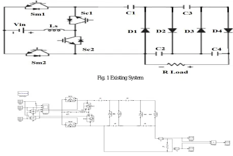
In this paper the transformerless Cockcroft Walton voltage multiplier is consider as existing circuit. The existing converter [1][3][4] consists of one inductor Ls (boost inductor), four switches (Sm1, Sm2, Sc1, and Sc2). In this existing circuit switches are used are in same ratings and the voltage stress across of all the switches are same, these four switches are divided into two groups called group 1 & group 2. The switches Sm1 & Sc1 are called group 1 switches and the switches Sm2 & Sc2 are called group 2 switches. These switches are operated in two different ranges and they are defined as fsm and fsc respectively. The both fsm and fsc frequencies should be as high as possible so that we can use smaller inductor and capacitors.
Technology (IJRASET)
[image:3.612.69.529.134.442.2]group 2 switches. But the existing circuit have many disadvantages & the main disadvantage is current rating. While increasing no. of stages for generating required high voltage, the current value become very low (i.e.) when the stages increased more than particular limit the current value become approximately zero. So there is a limitation for increasing no. of stages, these stage limitation is based on the input voltage value. The current value is very low means the output voltage is not a valid one.
Fig. 1 Existing System
Fig. 2 Simulation of Existing Circuit
The simulation diagram of the transformerless Cockcroft Walton Voltage Multiplier is given in Fig. 2. It is a simple two stage transformerless Cockcroft Walton circuit. It is made up of four capacitor and for diodes. In an n-stage CW voltage multiplier, there are N (= 2n) capacitors and N diodes n=2 (2-stage). The input voltage for Cockcroft-Walton (CW) generator is 230V, Output voltage is 900V, output current is 1.8Amp, and Output power is 3500W.
III. PROPOSED CIRCUIT
[image:3.612.132.475.558.697.2]The proposed circuit is based on the Flipped circuit concept. It is shown in Fig. 3.
Technology (IJRASET)
As shown in Fig.3, the proposed CW voltage multiplier is constructed by a flipped cascade connection of the stages. It is made up of six capacitor and eight diodes which is connected with DC voltage source, through switching circuit, like as shown in the above diagram. Where the diodes D5, D6, D7, D8, Capacitors C1, C3, C5, C6 are formed the loop 1 and the diodes D1, D2, D3, D4, Capacitors C1, C2, C3, C4 are formed the loop 2. In this circuit the loop 1 and loop are worked simultaneously.
[image:4.612.68.546.234.360.2]In general Cockcroft Walton voltage multiplier circuit transformer is present this causes many problems. The space consumption is the major issue, while increasing the voltage range the capacity of transformer also increased, which means the size of transformer is increased. So the space consumption is increased and the maintenance also required. This problem was overcome by the proposed circuit. In this circuit the current value was increased the parallel operation of the flipped circuit. (i.e.), the loop 1 and loop 2 are operated separately and simultaneously.
Fig. 4 Simulation of Proposed Circuit
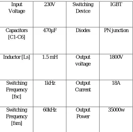
In Modified n-stage CW voltage multiplier, there are N (= 3n) capacitors and 4N/3 diodes n=2 (2-stage). The input voltage for Proposed Cockcroft-Walton (CW) generator is 230V, Output voltage is 1800V, output current is 18Amp, and Output power is 35000W. The proposed circuit is designed for 2 stage, for more high voltage value by increasing the no of stages the required high voltage was obtained. The simulation diagram of the proposed circuit is shown in Fig. 4. The simulation configuration details are given in the following Table.1.
Table I Simulation Configuration Input
Voltage
230V Switching
Device
IGBT
[image:4.612.175.438.455.715.2]Capacitors [C1-C6]
470µF Diodes PN junction
Inductor [Ls] 1.5 mH Output
voltage
1800V
Switching Frequency
[fsc]
1kHz Output
Current
18A
Switching Frequency
[fsm]
60kHz Output
Power
Technology (IJRASET)
IV. OUTPUT
A. Output Voltage
The output voltage of the proposed circuit to the input voltage of 230V is 1800V (1.8KV). Where, the output voltage is 8 times multiplied by the input voltage.
[image:5.612.43.568.137.386.2]V out = 8 Vin
Fig. 5 Output Voltage
The proposed circuit is designed for 2 stage, for more high voltage value by increasing the no of stages the required high voltage was obtained.
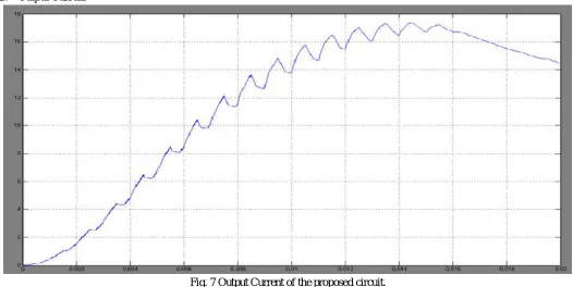
B. Output Current
Fig. 7 Output Current of the proposed circuit.
[image:5.612.42.568.437.701.2]Technology (IJRASET)
C. Output PowerFig. 9 Output Power of Proposed System
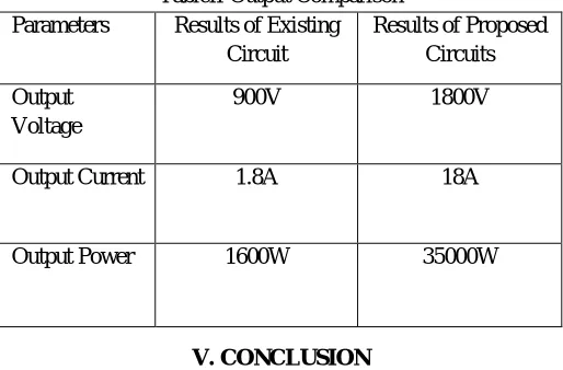
The output power of the proposed circuit is 35000W. It is 20 times greater than the output power of the existing circuit’s output power.
TableII Output Comparison
Parameters Results of Existing
Circuit
Results of Proposed Circuits
Output Voltage
900V 1800V
Output Current 1.8A 18A
Output Power 1600W 35000W
V.CONCLUSION
In this paper, a high step-up DC-DC converter based on Modified Cockcroft Walton Voltage Multiplier has been presented to obtain a high output voltage gain with quit large output current and high output power. Finally, the simulation results are proved using MATLAB SIMULINK
REFERENCES
[1] Nileena P. Subhash,” A High Step-Up Converter Using Transformerless Cockcroft-Walton Voltage Multiplier for a PV System”, IJIRSET. , vol. 3, Feb. 2014.
[2] Chitra Sharma1, “Low Cost High Voltage Generation: A Technique For Educational Laboratory”, IJSETR. , vol. 4, Dec. 2014.
[3] R. Prince, “ DC-DC Converter Based On Cascade Cockcroft-Walton Voltage Multiplier for High Voltage Gain without Using Transformer”, IJESIT. , vol. 2,Mar. 2013.
[4] Meghana G Naik,” Transformerless DC-DC Converter Using Cockcroft-Walton Voltage Multiplier to Obtain High DC Voltage”, IJERA. , vol. 4, Nov. 2014
[5] W. Li and X. He, “Review of nonisolated high-step-up dc/dc converters in photovoltaic grid-connected applications,” IEEE Trans. Ind. Electron., vol. 58, no. 4, pp. 1239–1250, Apr. 2011.
[6] C. S. Leu, P. Y. Huang, and M. H. Li, ―A novel dual-inductor boost converterwith ripple cancellation for high-voltage-gain applications,‖ IEEETrans. Ind.
Electron., vol. 58, no. 4, pp. 1268–1273, Apr. 2011.