5
IX
September 2017
Design of a High Temperature Solid Oxide Fuel
Cell: A Review
Pankaj Kalra1, Rajeev Kumar Garg2, Ajay Kumar3
1Research Scholar, I.K. Gujral Punjab Technical University, Kapurthala – 144603, Punjab, India. 2Department of Chemical Engineering, SBSSTC- Ferozepur- 152004 Punjab India 3Department of Applied Science & Humanities, SBSSTC- Ferozepur- 152004 Punjab India
Abstract: Fuel cells are for electrochemical devices converting the chemical energy of a fuel gas typically hydrogen into electrical energy without involving direct combustion. One of the upcoming fuel cell type, a SOFC, has all the components in the solid phase, and is composed of nano-ceramic composite materials, operates at elevated temperatures ranging from 800-1000C. Lowering the working temperature of SOFC in the range 600C-800C is under research to increase life-time and to reduce operating cost. To achieve this, electrolytes with good ionic conductivity at intermediate temperatures should be employed. SOFCs have suitable perspectives to replace their classical primitive combustion counterparts for the distributed generation of electrical energy. In addition, this technology does not produce significant amounts of environmental pollutants such as nitrogen oxides compared with internal combustion engines. The SOFCs have high conversion efficiency and low environmental impact than traditional energy conversion systems. This review deals with a design of a high temperature SOFC with particular emphasis on its thermodynamics, advanced material, design confugurations and transport equations and modern applications. Thermodynamics principles of these SOFCs are under study for employing them as ideal energy sources in transport, stationary, and distributed power generators. The review paper also gives insight into basic electrochemistry principles determining the operation of the SOFC, the kinetics of redox reactions during the SOFC operation, the mass and energy transport in a SOFC are described briefly to give an understanding of practical SOFC systems.
Keywords: Solid oxide fuel cell (SOFC),Combined Heat & Power (CHP), Open circuit voltage (OCV), internal reforming, methane reforming, water gas shift.
I. INTRODUCTION
Solid oxide fuel cells (SOFCs), a type of solid-state ionic based fuel cells devices, are expected to be employed in the stationary generation of energy as well in mobile generation in the coming decades and for clean and efficient distributed power generation. SOFCs has the distinct advantage thatthey are fuel flexible; their primary fuel being hydrogen either though fossil fuels, as well as from reforming reactions. They can be installed almost anywhere, and their capability of running on almost any fuel, have made them the ideal power generation system for future. Moroever, being completely quiet, they can be put in and around residential areas[1]-[3].
A. Principles of operation
In a single SOFC electro-chemical combination of fuel and an oxidant occurs across an ionic conducting electrolyte produces electricity as illustrated in Fig.1. The dense electrolyte is sandwiched between a porous anode and cathode. Fuel is fed to the anode; it undergoes an oxidation reaction, and releases electrons to the external circuit. Oxidant is fed to the cathode, accepts electrons from the external circuit, and undergoes a reduction reaction. The electrons flow in the external circuit from the anode to the cathode producing electricity[2],[4]. For the reactions to occur, a triple phase boundary is required which forms the meeting place of the gas phase, anode & electrolyte as depicted in Fig2.
The chemical reaction occurs at the anode and therefore the performance of an SOFC depends strongly on the anode structure. The reaction path in a SOFC depends on the anode and the cathode reactions. Hydrogen is adsorbed at the anode, ionised and the electrons are removed by the connection to the electrical load where the electrical work is used. Oxygen is adsorbed at the cathode connected with the load and ionised by the arriving electrons. The oxide ion is conducted by the electrolyte to the anode. The hydrogen ions (protons) and the oxide ion form a molecule of water[3],[5].
Fig.1 Principle of operation of a SOFC[1],[2] Fig.2 Schematic of three-phase boundary[1],[2]
The various reactions occuring in different regions of a SOFC are as follows: 1) The Cell reaction
The Overall cell reaction involves oxidation of hydrogen follows the equation H2 (g) + ½ O2 (g) → H2O(g)
The first reaction on the anode as H2(g) → 2H+ + 2e
-The second reaction that occurs on the cathode is ½ O2(g) + 2e- → O
2-The oxide ion O2- is conducted through the electrolyte and arrives at the anode. At the anode, water forms according to the reaction 2H+ + O2- → H
2O
2) Reforming reactions: In natural gas fuelled SOFCs, the gas enters the flow-channel pre-reformed and contains at least CH4, H2, CO, H2O and CO2. The high temperature of operation of SOFCs reforms the natural gas to produce H2 and CO which acts as true fuel of SOFC[6],[7]. It is generally thought that for a gas mixture containing CO and H2, electro-oxidation of H2 dominates over that of CO. In fact, it has been reported that approximately 98% of the current is a result of the electrochemical conversion of hydrogen. Although much of the reforming is expected to occur in the electrode, steam reforming does occur in the flow channels. Typical reaction involve partial steam reforming of methane as
CH4(g) + H2O(g) 3H2(g) + CO(g)
If CO is present, the water-gas shift reaction becomes very important since it affects the concentration of hydrogen at the reaction sites
CO(g) + H2O(g) CO2(g) + H2(g)
In excess of steam, the complete steam reforming of methane also takes place as per the following reaction producing more H2 and CO2.
CH4(g) + 2H2O(g) 4H2(g) + CO2(g)
In the above reactions, steam reforming is an endothermic reaction while the water shift reaction and cell reaction are exothermic. These reactions should be incorporated into the model as species and energy sources and sinks preformed an SOFC model where the temperature in the fuel cell was coupled to the temperature in the endothermic reformer.
C. Thermodynamics of a SOFC
Fig.3 Energy balance of a reversible fuel cell
The electric current I produced in a SOFC is a linear function of the molar flow rate of the electrons or the molar flow of the spent fuel
F
n
F
n
N
e
n
I
el.(
)
el
2
H2.
…………..(1)
F being the Faraday constant or the charge on one mole of electrons & N is the Avagadro’s No. The open circuit voltage generated in a SOFC is given by:
F
G
E
f2
…………..(2)The maximum electrical energy ηrev available is equal to the change in Gibbs free energy, maximum possible efficiency is given by
% 100 = rev) ( possible efficiency Maximum f f h G
…………..(3)
This maximum efficiency limit is sometimes known as the ’thermodynamic efficiency’.
The four major irreversibilities that are incorporated leading to a reduction in actual efficiency of a SOFC[8] and thus a drop in open circuit voltage are outlined briefly here:
(i) Activation losses, ηAct caused by the slowness of the reactions taking place on the surface of the electrodes. (ii) Ohmic losses,
ηohm caused due toresistance to the flow of electrons through the material of the electrodes and the various interconnections, as well
as the resistance to the flow of ions through the electrolyte. (iii) Mass transport or concentration losses, ηConc results from the change
in concentration of the reactants at the surface of the electrodes as the fuel is used. Fig4 shows the OCV and various losses
Fig. 4 Open circuit voltage fall due to polarization
An electrochemical analysis based on deviation from ideal performance is proposed at each slice. Considering the electrodes to be equilibrium surfaces [r] the Nernst voltage is defined by
O H
P P PH O
2 2 2 P T, ln nF RT E ENernst …………..(4)
The cell potential Ecell is being calculated by subtracting these over-potential from the Nernst potential[1],[8].:
conc ohm act Nernst cell
E
E
…………..(5)The electrical power produced by the fuel-cell is calculated by:
i
E
W
cell
…………..(6)
II. ENGINEERINGMATERIALSINSOFC
[image:4.612.155.459.428.516.2]hand, the electrolyte must have a very low electronic conductivity in order to avoid internal short-circuiting. Different components of SOFC should have similar thermal expansion coefficients to avoid build up of high mechanical stresses in a SOFC[4],[6]. Further, the materials and processing methods must be inexpensive and reproducible and must be easily scaled up from lab to industrial scales in order to be viable commercially. Further, better electrochemical performance can be achieved by having a higher TPB length per area of SOFC[2],[4]. The various components and their materials in use are mentioned below:
Ideally, an electrolyte is an ionic conductor for oxygen ions and an electronic insulator. The electrolyte must be gas tight and should be a purely ionic conductor with good conductivity. Yttria stabilized zirconia (YSZ) is a state of the art electrolytic material for an SOFCs. The conventional YSZ electrolyte SOFC electrolyte works well at 850 - 1000°C but at lower temperatures the ionic conductivity decreases. Other types of solid electrolytes like CGO-Ceria Gadolinium oxide in comparison to YSZ for intermediate temperature (500-600°C) operation of SOFCs, but they need a protective coating of a stable electrolyte on the fuel side because under anode environment they may become both ionic as well as electronic mixed conductors[1],[2].
The Anode represents the fuel electrode and must be stable in the reducing environment of the fuel. It should be electronically conducting, and must have sufficient porosity to allow the transport of the fuel to and the transport of the products of fuel oxidation away from the electrolyte / fuel electrode interface where the fuel oxidation reaction takes place. The nickel/yttria-stabilised zirconia (Ni/YSZ) cermet (ceramic-metal mixture) is at this moment the state of the art material for the anode. Nickel is used because it is one of the metals that is able to withstand the operating conditions of a SOFC i.e. reducing conditions and a very high temperature of 1000ºC. Other possible materials are cobalt and noble metals, but taking into account volatility, chemical stability, catalytic activity and cost, nickel appears to be the best candidate. YSZ is added to support the nickel-metal particles, to inhibit coarsening of the metallic particles and to provide a thermal expansion coefficient acceptably close to those of the other cell components[2],[4]. A good cathodic material must posses high electric and ionic conductivity, high catalytic activity for reduction of oxygen, should be chemical and thermal compatibility with the electrolyte, and chemically stable in an oxidizing atmosphere. Typically, cathode materials are Perovskite-type oxides of the type (ABO3), where A site can be a low valence substituted element and B site are cations in valence of 3+. LaMnO3 based perovskites are commonly used as cathodes. A typical strontium-doped lanthanum manganites (LSM) have high conductivity, relative good chemical stability, and a thermal expansion coefficient close to that of zirconia[4],[6].
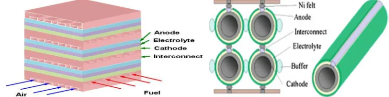
III. GEOMETRICALDESIGNSOFSOFC
[image:5.612.103.504.619.719.2]The performance of these new design cells is higher than that of cylindrical tubular cells, but still lower than that of anode -supported planar cells. One of the inherent advantages of tubular cell bundles is that the air and the fuel are naturally isolated because the tubes are closed at one end. Fig.6 shows a typical components of an electrolyte supported tubular SOFC stack bundle.
IV. GOVERNINGTRANSPORTEQUATIONS
From perspective of transport, a fuel cell consists of several components: flow channels (the fuel flow channel and air flow channel), electrodes (the anode and cathode), electrolyte, and interconnector.
A. The flow channels
The key function of flow channels is to allow the distribution of gases throughout the fuel cell to the porous electrodes with as little losses as possible[3]. The governing transport equations are:
1) The conservation of mass
0
)
.(
v
t
…………..(7)where ρ refers to the density of the flow in the channels and v the velocity vector.
2) The conservation of momentum
)
.(
)
.
(
P
vv
v
t
…………..(8)where P refers to the pressure in the channels and τ the stress tensor. 3) The species balance equation
i i i
i
vY
J
r
Y
t
.
)
.(
)
(
…………..(9)where Yi refers to the mass fraction of the ith species in the channels, Ji the diffusive flux of the ith species, and ri is the rate of production of species i per unit volume.
4) Energy conservation:
q
T
k
T
v
dt
dT
C
P(
.
)
2
………..(10)
where Cp refers to the specific heat, T the temperature, k the thermal conductivity, and q the heat source term per unit volume, for the substance in the flow channel .
B. The electrodes
The porous electrodes of SOFCs is the place where electrochemical reaction takes place. These electrodes serve several functions- allow for gas transport/ diffusion through the pores to the active sites, and provide a site for the electrochemical reactions to occur. The governing transport equations are:
1) Species balance equation: i i
i
J
r
Y
t
.
)
(
………..(11)where ε refers to the porosity of the electrode, and ri the rate of production of species i per unit volume within the electrodes. The diffusion is considered to occur only in the electrodes.
2) Energy conservation: In the porous structure, the energy conservation can be written by ignoring the convective heat transfer
as:
q
T
k
dt
dT
C
P
2
…………..(12)
where q includes the heat generated by the current flow through the electrodes.
V. COMMERCIALAPPLICATIONSOFSOFCS
SOFCs for stationary power generation systems of from 1-kW to 25-kW size have been fabricated and tested by several organizations. Several hundred 1-kW size combined heat and power units for residential application were field tested by Sulzer Hexis; however, their cost and performance degradation was high and stack lifetime too short. Siemens/ Westinghouse fabricated a 100 kW atmospheric power generation tubular SOFCs, system. The system was successfully operated for two years in the Netherlands on desulphurized natural gas without any detectable performance degradation. It provided up to 108 kW of ac electricity at an efficiency of 46% to the Dutch grid and approximately 85 kW of hot water for the local district heating system. Delphi Corporation has developed a 5kW auxiliary power unit on-board for automative application using anode-supported planar SOFCs. This unit was intended to operate on gasoline or diesel, which is reformed through catalytic partial oxidation. The building blocks of such an auxiliary power unit consisted of a SOFC stack, fuel reformation system, waste energy recovery system, thermal management system, process air supply system, control system, and power electronics and energy storage (battery) system . Delphi has reduced the mass and volume in successive generation auxiliary power units to meet the stringent automotive requirements; the remaining issues of start up time and tolerance to thermal cycling are presently being worked on.
A. Power Generation Systems
In general, SOFC system for a distributed power generation consists of three main parts: 1) A fuel processor to reform hydrocarbon fuels to hydrogen-rich gas
2) SOFC stack where the electric power is generated, and
3) A power conditioner for converting the DC power to utilizable AC power.
Fig7.Shows the typical components of SOFC based power generation system are arranged.
Fig.7 Typical power generation system Fig.8 SOFC system with combined heat and power.
The SOFC stack consists of an electric generator in which the individual cells are connected both in parallel and in series, to form a semi-rigid bundle. Nickel felt, consisting of long nickel fibers are sinter-bonded to each other, is used to provide soft, mechanically compliant, low-electrical resistance connections between the cells[1],[4],[9]. This material bonds to the nickel particles in the fuel electrode and the nickel plating on the interconnection for the series connection, and to the fuel electrodes of the two adjacent cells for the parallel connection.
B. Cogeneration of Combined Heat and Power (SOFC-CHP)
The high-quality of waste heat and electrical energy can be cogenerated in SOFC systems[1],[4],[10]. For the SOFC-CHP, the heat content of the outlet gas from a combustion process of unused fuel exiting a fuel cell stack with air in a combustion chamber (an afterburner) is recovered and provided to other parts in the SOFC system. In a practical cell operation, the useful heat from the SOFC is usually exploited in energy-requiring units, i.e., preheaters and reformers, to preheat cooling streams or to generate steam and hot water. Fig.8 shows a typical simplified SOFC-CHP system. The system efficiency of 85% can be achieved when the cogeneration of heat with power in the SOFC system is considered. The preliminary energy and mass balance analysis results showed that such a system has the capacity to produce electric power, heating and/or cooling for buildings and the total system efficiencies of higher that 87% in different modes has been reported.
C. Cogeneration of SOFC with Gas Turbine (SOFC-GT)
former, the combustor of the gas turbine is replaced with a heat exchanger in which air from the compressor is heated by the fuel cell exhaust. Under the indirect SOFC-GT hybrid system, the SOFC can be operated at atmospheric conditions. Although, it reduces the sealant requirement in the SOFC stack, the heat exchanger has to operate at very high temperatures and pressure differences[1],[10]. A typical SOFC-GT system is shown in Fig9. Below:
Fig.9. Simplified SOFC-GT system.
D. Cogeneration of SOFC: Chemical Production Approach
Another potential application of SOFC as an integrated co-generation of chemical production with electric power generation[1],[11]. In 1980 first demonstration chemical production approach of SOFC was for the conversion of NH3 to NO. This system consisted of a fuel cell reactor, external load and chemical product recovery unit. Yttria stabilized zirconia was employed as an electrolyte which was placed between porous Pt electrodes. NH3 diluted in Helium at a concentration of 4.59% was fed on the anode side while cathode side was exposed to air. The oxygen ions pass through the electrolyte to the anode, where they react with NH3. In the temperature range from 427 to 927°C, NO was obtained as a primary anodic product with an optimal yield over 60%. Significant amounts of by-product N2 were also formed due to the catalytic reaction between NH3 and NO on Pt electrode.
Another interesting chemical cogeneration process is the synthesis of hydrogen cyanide, which is widely used for adiponitrile (for Nylon 6/6) synthesis, used in fumigation as insecticide and photography. The cogeneration system utilizes a mixture of methane and ammonia (diluted in helium) as fuel. The cell was also made with a tube of YSZ enclosed in a quartz tube, containing a porous Pt electrode as the cathode and a porous rhodium and platinum electrode as the anode. Syngas can also be used as feedstock for hydrocarbon and methanol manufacture using SOFCs. An addition of catalyst layer on the anode yielded more stable methane conversion to syngas than without the catalyst.
VI. SUMMARY
[1] Kalra P. Garg R. and Kumar A., Solid Oxide Fuel Cell - A Future Source of Power and Heat Generation, Engineering Applications of Nanoscience and Nanomaterials, special edition of Material Science Forum, Trans Tech Publications, Switzerland Vol.757 pp 217-241 (2013).
[2] Singhal S. C. Kendall K. (editors), High Temperature Solid Oxide Fuel Cells: Fundamentals, Design and Applications, Elsevier, Oxford, 2003.
[3] Kalra P., Garg R. and Kumar A. , Modelling of a High temperature Solid oxide Fuel cell, Journal of Energy Technologies and Policy, ISSN 2224-3232 (Paper) ISSN 2225-0573 (Online)Vol.5, No.2, 2015.
[4] Singhal S. C., Solid Oxide Fuel Cells for Stationary, Mobile, and Military Applications,Solid State Ionics, Vol. 152-153, pp 405-410, 2002. [5] Larminie J. Dicks A., Fuel Cell Systems Explained, John Wiley & Sons Ltd, 2003.
[6] Singhal S. C., Advances in Solid Oxide Fuel Cell Technology, Solid State Ionics, Vol. 135, pp 305-313, 2000. [7] McIntosh S. Gorte R. J., Direct hydrocarbon solid oxide fuel cells, Chem. Rev. 104 4845-4865 (2004).
[8] H. Mahcene, H. Ben Moussa, H. Bouguetaia, B. Bouchekima and D. Bechki, Losses effect on solid oxide fuel cell stack performance, Fuel Cells Journal, (2006).
[9] Singhal S. C., Eguchi K., Yokokawa H., and Mizusaki J. (editors), Solid Oxide Fuel Cells 10 (SOFC-X) Electrochemical Society Transactions, Vol. 7, No. 1, ECS, Pennington, NJ, 2007.