Research Study on Behavior of Composite Stub
Column Experimentally and Analytically
Pritika Holey1,Bhushan Shinde21 PG Student Department of Civil Engg, GHRCEM Amravati, 2 Assistant Professor Department of Civil Engg , GHRCEM Amravati,
Abstract: The structural behaviour of concrete - filled steel tube (CFST) columns has been investigated using, ANSYS Software, experimental and analytical studies (Rankine’s). The effect of concrete compressive strength, thickness of steel tube, stiffeners a nd longitudinal reinforcement were considered. Specimens that have been studied consist of twenty one circular samples of 150 mm diameter and 5mm thickness and height of 300 mm. The tested samples were studied analytically using workbench by ANSY S (ver. 12) computer program. The results obtained from analytical method shows that, the convergence between analytical and e xperimental method failure load varied from (16.49 to 56.78 %)While the effect of compressive strength of concrete on columns having diameter/thickness (d/t) is 30 . Deformations of columns filled with normal concrete (25 MPa). The effect of diameter/thi ckness (d/t) ratio on the ultimate strength of (CFST) columns will have a reverse action, when of (d/t) decreases the caused incre asing in ultimate load capacity of columns for circular samples depending on the type of stiffened, compressive strength of concr ete and ratio of (d/t).
Keywords: Stub column, Composite column, Concrete-filled steel tube column.
I. INTRODUCTION
Steel-concrete composite columns were used for over a century. At the beginning it was used to provide fire protection to steel struc tures. Afterwards, the concrete encased columns strength properties were also considered in the design. However, the researches int o concrete filled steel tubes (CFST) did not begin until the 1960. Nowadays, the composite structural elements are increasingly used in tall buildings, bridges and other types of structures. The steel concrete composites are considered as an advantageous system for carrying large axial load benefitting from the interaction between the concrete and the steel section. The steel section reinforces the concrete to resist bending moments, tensile and shear forces. The concrete in a composite column reduces the potential for buckling of the steel section in addition to resisting compressive loading. There are two types of steel-concrete composite columns which are commonly used in buildings. Those with steel section in-filled with concrete and those with steel section encased with concrete.
II. MATERIALS AND METHOD
A. Following are some models which are studied during this project
B. It consists of mild steel column is 300mm long. One end is fixed and other end hinged. The outer diameter of column is 160mm and 5mm thickness and the grade of conctere is
C. There were total seven numbers of models made details of each shown in a below table. D. Diagrammatic representation of all the models has been also shown in fig no1
E. Total number of models
Model M1 Hollow circular pipe.
Model M2 Hollow circular pipe provided with stiffener at the middle section
Model M3 Hollow circular pipe provided with stiffener at the top and bottom.
Model M4 Hollow circular pipe filled with concrete and stiffener provided at the middle section.
Model M6 Hollow circular pipe carrying longitudinal reinforcement without concrete.
Model M7 Hollow circular pipe filled with concrete and carrying longitudinal reinforcement.
F. Method of analysis
The models are analysed by three methods given below.
1) Analytically by Rankine’s method: It is an empirical formula used for calculation of ultimate load both for short and long colum n. Rankine’s formula is also known as rankine Gordon formula. It gives the ultimate load that column can bear before failure. If column is short, calculate load will be known as crushing load. And load will be buckling or crippling load, in case of long col umn.This formula only gives the ultimate load, but columns are designed on safe load. In order to get safe load, divide ultimate load (load obtained from rankine’s formula) with factor of safety (F.O.S)
2) Sample calculation for model 1: Rankine`s formula E = 2 * N/ = 320 N/
= = =7319.42 .K = = 54.95mm Le = 212.13mm . =777 kN
Deformation calculation
ᵟ = = = 0.48 mm
3) ANSYS software: ANSYS is a structural analysis program that is most widely used for modeling and analyzing a number of stru ctures ANSYS is a complete FEA package used by engineers in virtually all fields of engineering. ANSYS Mechanical is a finit e element analysis tool for structural analysis, including linear, nonlinear and dynamic studies. This computer simulation produ ct provides finite elements to model behavior, and supports material models and equation solvers for a wide range of mechanica l design problems. ANSYS as a software is made to be user-friendly and simplified as much as possible with lots of interface op tions to keep the user as much as possible from the hectic side of programming and debugging process. ANSYS works on the pr inciples of FEM i.e. finite element method. FEM has the advantages of improved visualization, lesser design cycle time, lesser number of prototypes, lesser number of testing required, and decrease in cost of production. ANSYS 12 is the easiest, most prod uctive solution The FEM model of composite column was developed considering above physical properties in FEM commercia l software package ANSYS 12.
Model 4 Model 5 Model 6
4) Experimental investigation: The models of stub columns are prepared and tested experimentally by using compressive testing m achine (CTM) of capacity 3000 kN. Concrete of grade M25 is prepared for the models and grade of steel is Fe 415. Rate of load ing is kept 5kN/s during testing of models. Models were tested after 14 days of curing. During the experiment buckling load an d deformation along the line of action are measured.
Making hole Smoothing surface Compacted by iron rod
Casting Testing Failure specimen
Fabrication and casting of columns, all specimen arranged before casting the concrete, then concrete mix was placed and well comp acted by means of iron rod, the top surface of columns was finished level. Before testing, the top surface of CFST columns were sm oothened by a scraper machine to make the surfaces of concrete and steel lying on the same elevation, and therefore ensuring a trans fer of load to both concrete and steel at all levels. Compressive testing machine with capacity of 3000kN was used to deformation of columns.
shown and discussed below.
Table 1: Result of failure load anddeformation of stub column byanalytical study .
MODEL LOAD (kN)
along the line of action l oad
777 0.49
814.37 0.45 852.43 0.42 1517.24 0.41 1589.93 0.39 928.56 0.24 1546.48 0.22
Table 2: Result of deformation of stub column by ANSYS software method.
Model Load (kN)
Pressure (Mpa)
Deformation along the li ne of action load. (mm)
M1 777 320.58 0.487
M2 814.37 335.99 0.480
M3 852.43 351.7 0.476
M4 1517.24 75.5 0.466
M5 1589.93 79.11 0.480
M6 928.56 380.63 0.286
[image:6.612.138.477.471.662.2]M7 1546.48 77.12 0.403
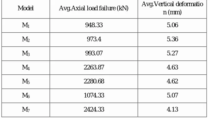
Table 3:Result of failure of load and deformation of stub column by Experimental method.
Model Avg.Axial load failure (kN) Avg.Vertical deformatio n (mm)
M1 948.33 5.06
M2 973.4 5.36
M3 993.07 5.27
M4 2263.87 4.63
M5 2280.68 4.62
M6 1074.33 5.07
M7 2424.33 4.13
Fig: 1 Graphical Representation of Comparison of deformation between analytical method and ANSYS software
From the graph it has been observed that maximum percentage difference for deformation is for model seven (M7which is (Hollow c
ircular pipe carrying longitudinal reinforcement filled with concrete) by two distinct method.
Fig: 2 Graphical Representation Comparison of failure of load by analytical method, ANSYS software method and Experimental me
0.49
0.45
0.42 0.41
0.39
0.24
0.22
0.48 0.48 0.47
0.46 0.48
0.286
0.4
0 0.1 0.2 0.3 0.4 0.5 0.6
M1 M2 M3 M4 M5 M6 M7
Comparision of deformation by
Analytical and ANSYS
ᵟAnalytical (mm)
The experimental and analytical results of the tested specimens (twenty one concrete–filled steel tube stub columns) have been studi ed. Effect of compressive strength of concrete, steel tube thickness, scheme of stiffeners and longitudinal reinforcement have been st udied Graph above indicating higher value of failure load during experimental investigation.
IV. CONCLUSION
From experimental results, CFST columns show higher ductility after maximum load. The load can reach up to 56.78% of the ultim ate load capacity of CFST columns, especially for reinforced and stiffened columns
The effect of (diameter-thickness) ratio on ultimate strength of CFST columns will have a reverse relation. When increasing thickne ss of tube this ratio will decrease, then ultimate strength will increase.The effect of compressive strength on unstiffened CFST colu mns is more than for stiffened and reinforced CFST columns. The ultimate load capacity for two cross stiffened CFST columns is m ore than for one cross stiffened CFST columns and more than for unstiffened CFST columns. The ultimate load capacity for reinforc ed (circular) CFST columns is more than for unstiffened (circular) CFST columns. The filling concrete will enhance the steel carryi ng capacity so that all the section will reach its limit state and avoid the possibility of buckling until cracking induced in concrete at high load levels. At the same time the steel shell will confine the concrete and improve its strength and ductility.
REFERENCES
[1] Anil Kumar Patida , “Behavior of Concrete Filled Rectangular Steel Tube Column”,Journal Of Mechanical and Civil Engineering, Dec 2012, 46-5.
[2] Cheng-Chih Chen , Jian-Ming Li, C.C. Weng, “ Experimental behavior and strength of Concrete - encased compositebeam–columns with T-shaped steel section under cyclic loading”,Journal of Constructional steel Research,27 Jun 2005,863-881.
[3] João Batista Marques de Sousa Jr. and Rodrigo Barreto Caldas,“Numerical Analysis of Composite Steel-Concrete Columns of Arbitrary Cross Section”, Journal of Structural Engineering, November 2006,1721-1730.
[4] Chang-Soo Kim, Hong-Gun Park,“Eccentric Axial Load Capacity of High-Strength Steel-Concrete Composite Columns ofVarious Sectional Shapes” Journal of American Society of Civil Engineers. Oct 2013, 04013091-1- 04013091-12.
[5] Eiichi Inai, Akiyoshi Mukai, Koji Mori,“Behavior of Concrete-Filled Steel Tube Beam Columns” Journal Of American Society of Civil EngineersOct 2004,
189-202.
[6] Tinu Mathew , “Analysis of Tubed Steel Reinforced Columns under Axial Loading” International Journal of Science Technology & Engineering August 2016 2349-784
[7] Dennis Lam, EhabEllobod and Ben Young,“The behavior and design of axially loaded concrete-filled steel tube circular stubcolumns”, International Journal of I Research in Science Engineering and Technology, 2005.