© 2017, IRJET | Impact Factor value: 5.181 | ISO 9001:2008 Certified Journal | Page 1214
FOOTSTEP POWER GENERATION SYSTEM
Mrs. Krupal Dhimar
1, Miss. Krishna Patel
2, Miss. Zeel Patel
3, Miss. Nisha Pindiwala
41
Assistant professor, Mahavir Swami College of Engg. & Tech., Gujarat, India
234
Students, Electrical Engg.,Mahavir Swami College of Engg. & Tech., Gujarat, India
---***---Abstract -
Power crisis is being one of the serious topics tobediscussed. There for possible solution for this to provide sufficient amount of power using renewable energy. Among these resources, human population is the only far and away and all weather resource that has not been utilized .we can use proper method required amount of power can be obtain from this resource. We have thought the idea to utilize human walking power to produce electricity and also we have designed a method named foot step power generation platform, when people walk on the platform, electricity is generated in this system uses the pressure due to weight of the person walking on the platform and stored using batteries. For batter result cascade H bridge inverter used. A 5-level three-phase cascaded hybrid multilevel inverter that consists of a standard 3-leg (one leg for each phase) and H-bridge in series with each inverter leg with separate DC voltage sources, 24V and 48V. The control signals for this hybrid multilevel inverter are implemented by a using SPWM signal modulated technique and digital technique.
Key Words: Renewable energy, Gears, electric power,
Cascaded H-Bridge multilevel inverter (CHB), Pulse Width Modulation (PWM).
1.INTRODUCTION
Now-a-days electricity has become the basic need of every human being. Electricity is used in each and every place. We cannot live without electricity. Electricity is used in day to day life, industries, transportation, etc. Now to fulfill this increasing demand of electricity, engineers are finding new ways to generate it.
There are many places where there is no electricity .so we are generating electrical power by means of renewable energy, by simply walking on the footstep .non-renewable energy is very less so renewable energy is very much in demand now a days. As the availability of conventional energy declines, there is need to find alternate energy sources. All most all the state electricity departments in our country, they are unable to supply the power according to the demand. The power produced by these companies is not even sufficient for domestic utilities; in such critical situation it is very difficult to divert the energy for other public needs. New generation need electricity for each and every small
appliance they use. Many energy is being wasted and exhausted, like humans bio energy is being wasted, so we can make it possible to use that energy in making a great invention.
There by an alternative source must be discovered. Here we going to use renewable energy using footstep is converting mechanical energy into electrical energy. It is clear, safe, and free, does not pollute the environment and thus will be an extremely viable alternative in the days to come. As our population is increasing day by day the pedestrians are moving one after another continuously on the foot paths as well as in the cities, the footstep mechanism generates nonstop energy, which can be stored and utilized to energize the street lights. Here the concept is to convert the mechanical energy in to electric energy.
Proposal for the utilization of waste energy of foot power with human locomotion is very much relevant and important for highly populated countries like India and China where the roads, railway stations, bus stands, temples, etc. are all over crowded and millions of people move around the clock. This whole human/bio-energy being wasted if can be made possible for utilization it will be great invention and crowd energy farms will be very useful energy sources in crowded countries. Walking across a "Crowd Farm," floor, then, will be a fun for idle people who can improve their health by exercising in such farms with earning. The electrical energy generated at such farms will be useful for nearby applications.
© 2017, IRJET | Impact Factor value: 5.181 | ISO 9001:2008 Certified Journal | Page 1215 in the following five levels: zero, +1/2Vdc, Vdc, -1/2Vdc and
-Vdc. As the number of output levels increases, the harmonic content can be reduced.
2. THERMODYNAMIC RULE
As first rule of thermodynamics says that “energy is neither created and it cannot be destroyed, it can only betransformed from one form to another.” So we are converting solar energy into electrical form.
3. WORKING PRINCIPLE
The finish graph of the stride control era is given beneath. One and only stride is slanted in certain little edge which is utilized to create the power. The pushing force is changed over into electrical vitality by appropriate driving course of action. The rack and pinion, spring course of action is settled at the slanted stride. The spring is utilized to give back the slanted stride in same position by discharging the heap. The pinion shaft is associated with the supporter by end course as appeared in fig. The bigger .sprocket additionally combined with the pinion shaft, so it is running the same speed of pinion. The bigger sprocket is coupled to the little cycle sprocket with the assistance of chain (cycle). This bigger sprocket is utilized to exchange the revolution drive to the littler sprocket. The littler sprocket is running same bearing for the forward and turn around heading of rotational development of the bigger sprocket. This activity locks like a cycle accelerating activity.
The fly haggle wheel is likewise coupled to the littler sprocket shaft. The flywheel is utilized to expand the rpm of the littler sprocket shaft. The rigging wheel is coupled to the generator shaft with the assistance of another apparatus wheel. The generator is utilized here, is perpetual magnet D.C Stepper Motor. The created voltage is 12Volt D.C. This voltage is further intensified utilizing IC MC34063 DC-DC convertor and is put away to the Lead-corrosive 12 Volt battery
3.1 BLOCK DIAGRAM
Fig.1.block diagram
3.2
MECHANICAL CIRCUIT DIAGRAM
P.M.D.C GENERATOR
SPRING
RACK
PINION
BEARINGS
SPRACKETS
CHAIN DRIVE
GEAR WHEEL
FLY WHEEL
BATTERY
SHAFT
© 2017, IRJET | Impact Factor value: 5.181 | ISO 9001:2008 Certified Journal | Page 1216
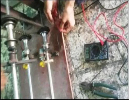
Fig.2. Construction of foot step power generation system.
A. Stationary plate:
It is a base plate which is associated with other inflexible RCC steps and it gives working stage to the moving force venture by method for bearing backing.
B. Control Step:
It is rectangular Cast Iron plate which is bolstered by two profound score metal balls with stationary plate.
C. Open Coil Helical Spring:
Two pressure springs are utilized to convey the heap on the edge of the power step. Springs are likewise to accommodated the proceeds with wavering of the power step.
D. Interfacing Rod:
It is to interface the power step and wrench shaft. It transmits the direct movement of the power venture to the wrench.
E. Wrench Shaft:
One end of the wrench shaft is settled and bolstered by a metal roller. Another end is associated with the flywheel.
F. Fly Wheel:
The circuit of the flywheel is as pulley sort to manage the belt drive which interfaces the flywheel and generator shaft.
G .Belt Drive:
It is to associate the flywheel and the gen shaft. It duplicates the power from the flywheel to the little pulley shaft (generator shaft).
4. INVERTER
The power in the battery is in DC mode and the engine that drives the wheels for the most part uses air conditioning power, subsequently there ought to be a transformation from DC to air conditioning by a power converter. Inverters can do this transformation. The least complex topology that can be utilized for this change is the two-level inverter that comprises of four switches. Every switch needs an against parallel diode, so there ought to be additionally four hostile to parallel diodes. There are likewise different topologies for inverters. A multilevel inverter is a power electronic framework that blends a sinusoidal voltage yield from a few DC sources. These DC sources can be energy components, sunlight based cells, ultra capacitors, and so forth. The fundamental thought of multilevel inverters is to have a superior sinusoidal voltage and current in the yield by utilizing switches as a part of arrangement. Since numerous switches are placed in arrangement the exchanging edges are essential in the multilevel inverters since the greater part of the switches ought to be exchanged in a manner that the yield voltage and current have low symphonious twisting. Multilevel inverters have three sorts. Diode cinched multilevel inverters, flying capacitor multilevel inverters and fell H-connect multilevel inverter. The THD will be diminished by expanding the quantity of levels. Clearly a yield voltage with low THD is attractive, yet expanding the quantity of levels needs more equipment, likewise the control will be more entangled. It is a tradeoff between value, weight, intricacy and a decent yield voltage with lower THD.
Three types of multilevel inverter have been used.
1. Cascaded H-bridge multilevel inverters 2 .Flying Capacitor multilevel inverters 3. Diode Clamped multilevel inverters
4.1
CASCADED H-BRIDGE MULTILEVEL
INVERTER
© 2017, IRJET | Impact Factor value: 5.181 | ISO 9001:2008 Certified Journal | Page 1217 A n level fell H-connect multilevel inverter needs 2(n-1)
exchanging gadgets where n is the quantity of the yield voltage level.
5-level Cascaded H-bridge multilevel inverter :-
The output voltage of this inverter has five levels like in the above multilevel inverters. This inverter consists of two H-bridge inverters that are cascaded. For a five-level cascaded H-bridge multilevel inverter has eight switching devices are needed.
Fig.3 Simulation of 5-level Cascaded H-bridge multilevel inverter.
[image:4.595.318.576.125.258.2]Fig.4 Simulation of 5-level Cascaded H-bridge multilevel inverter.
Table 1: Switching sequence of single leg 5 level
For an output voltage level Vo = Vdc/2, S11, S411 are turned on
For an output voltage level Vo = Vdc, S11, S41 and S12, S42 are turned on
For an output voltage level Vo = 0, all switches are turn off
For an output voltage level Vo = -Vdc, S21, S31 and S21, S22 are turned on
For an output voltage level Vo = -Vdc/2, S21, S31are turned on.
5. RESULT
[image:4.595.29.266.247.490.2] [image:4.595.308.579.499.709.2] [image:4.595.53.266.536.714.2]© 2017, IRJET | Impact Factor value: 5.181 | ISO 9001:2008 Certified Journal | Page 1218
Fig6 footstep power generation output
6 .ADVANTAGES UNIQUE FEATURE &
APPLICATION
6.1. ADVANTAGES
1. It is a renewable source of energy. 2. it saves agricultural land.
3.It is non harmful to atmosphere.
4. No smoke or ash or any toxic chemical is produced. 5.Utilized human waste walking energy in to electrical energy.
6 .Economic
7. Easy maintenance
6.2. Unique Features
1. Reduce Environment pollution. 2. Utilized renewable source of energy. 3. Easy to install.
4. Low Cost.
5. Utilize solar and weight or pressure energy
7. CONCLUSION
This technique produce the electric power without dirtying our surrounding. The waste energy supplied by human is used in this frame-work. This energy source is ceaseless & renewable . In addition we are certain that this technique for power era will be utilized for rustic jolt & to satisfy our energy needs. Additionally this frame-work looks extremely eco-accommodating from the natural perspective , MLI have become more attractive for to their advantages over conventional 3-level PWM inverters. They offer improved output waveforms , smaller filter size ,lower EMI , lower THD.
REFERENCES
(1) v.jose ananth vino,ap, “power generation using foot step”,ijett ,volume
1,issue 2,may 2011
(2) a.r.sri harsha*1, a. Srija reddy1,” foot step power generation system
For rural energy application to run ac and dc loads with gsm Based battery voltage monitoring”, international journal of engineering
& science research\
(3) title:-foot step power generation system for rural energy application to run ac and dc loads with gsm based battery voltage monitoringAuthor:- a.r.sri harsha1, a. Srija reddy1 (4) ) title:-power generation using foot step
Author:- v.jose ananth vino,ap. Journal:-volume 1,issue 2,may 2011
(5) titel:-non-conventional energy using foot step by converting mechanical energy into the electrical energy Author: shrinath bhosle1
Assistant professor, department of mechanical engineering, bkit bhalki, karnataka, india
Proceeding of ncriet-2015 & indian j.sci.res. 12(1):332-343, 2015
(6) odriguez, J., J.S. Lai and F.Z. Peng, 2002. Multilevel inverters: A survey of topologies, controls and applications. IEEE Trans. Ind. Electron., 49: 724-738. (7) Rodriguez, J., P.W. Hammond, J. Pontt, R. Musalem, P. Lezana and M. Escobar, 2005. Operation of a medium-voltage drive under faulty conditions. IEEE Trans. Ind. Electron., 52: 1080-1085. Tolbert, L.M. and T.G. Habetler, 1999. Novel multilevel inverter carrier-based PWM method. IEEE Trans. Ind. Applic., 35: 1098-1107.
(8) Nabae, A., I. Takahashi and H. Akagi, 1981. A new neutral-point-clamped PWM inverter. IEEE Trans. Ind. Appl., IA-17: 518-523. Park, S.J., F.S. Kang, M.H. Lee and C.U. Kim, 2003. A new single-phase five-level PWM inverter employing a deadbeat control scheme. IEEE Trans. Power Electron., 18: 831-843.
(9)The IC 555 Timer Applications Source book By: HOWARD M. BERLIN
(10)Mechatronics and measurement systems - By: DAVID G. ALCIATORE And MICHAEL B. HISTAND
(11)Electronic Devices & Circuits – ALLEN MOTTERSHEAD (12) Electronic Instrumentation and Measurement Techniques By: William David Cooper
© 2017, IRJET | Impact Factor value: 5.181 | ISO 9001:2008 Certified Journal | Page 1219
BIOGRAPHIES
Mrs. Krupal Dhimar is a asst. professor in MSCET Surat. She has 2 year of experience in Electical Engineering.
Miss. Krishna Patel is final year student in electrical department in MSCET, Surat.
Miss. Zeel Patel is final year student in electrical department in MSCET, Surat.