© 2017, IRJET | Impact Factor value: 5.181 | ISO 9001:2008 Certified Journal
| Page 2140
BER PERFORMANCE OF HIGH DATA RATE WIRELESS OPTICAL SYSTEM
FOR SHORT DISTANCE
Preeti Chauhan
1, Shalini Kashyap
2, Mohammad Umar
31
Mtech Student, Dept. of ECE, Satya College of Engineering & Technology, MDU Rohtak, India
2,3Assistant Professor, Dept. of ECE, Satya College of Engineering & Technology, MDU Rohtak, India
---***---Abstract -
This research paper represents basic studyanalysis of wireless optical communication systems which can be used for short distance application area like indoor, office, small factories etc. Wireless optical communication link used in this research work is IR LED based 12.5 GHz transmission system. Operating wavelength of IR LED considered is 760nm.. The performance of wireless optical communication is analyzed in this paper in terms of bit error rate and effects of data rate over bit error rate.
Key Words: Optical wireless communication, Bit error rate, Beam footprint, Data Rate.
1. INTRODUCTION
In recent years, wireless communications have significantly evolved because of the advanced technology of smartphones, movable devices, and conjointly the expansion of net of Things, e-Health, e Commerce, intelligent transportation systems, and social networking. Forecasted by Cisco, the wireless mobile traffic square measure aiming to be dominant over the knowledge network by 2017. plenty of recently, we have got seen the use of Optical Wireless Communications (OWCs) in mobile phones as an additional communication technology like cellular systems, Wi-Fi and Bluetooth, therefore on unravel the spectrum crunch and provide high information rates in urban surroundings and huddled locations. OWCs provide many edges like free license, wide system of measurement, inherent security, and no interference and represent a complementary technology to the frequency technologies considerably inside the rising 5G primarily based wireless communication networks and on the so much aspect. however, the widespread preparation of OWC systems, namely, infra-red, no particulate radiation Communication, and Free-Space Optical Communications, is facing selection challenges just like the impact of the weather, safety regulation, device performance, compatibility with existing systems, the killer application, complexity, and cost. Moreover, inside the last decade, we have got seen a growing trend in analysis and development activities inside the rising field of OWC, covering VLC and FSO for indoor and out of doors applications, furthermore as underwater communications. The optical spectrum will function a decent spectrum resource for wide band wireless communications. The benefits of optical wireless communications chiefly consist 2 aspects: the potential
massive transmission information measure thanks to the high frequency carrier, and therefore the communication security thanks to no frequency radiation. Therefore OWC are often applied within the eventualities wherever the radio silence is needed or the frequency radiation might cause explosions, as an example within the battle field or some special areas within the storehouses.
OWC are often performed within the spectrum, the visible radiation spectrum, and therefore the immoderate violet spectrum. Daily OWC applications usually cater for the visible radiation spectrum, which might be achieved victimization the lighting emitting diode (LED) because
the transmitter and therefore the photodiode
(PD)/avalanche photodiode (APD) because the receiver. A typical application of the visible radiation communication (VLC) is that the indoor VLC autocell network, wherever the LEDs square measure mounted on the ceilings, and therefore the user instrumentation (UEs) embody hand-held terminals, robots, and intelligent piece of furniture and appliances. Data and management messages square measure transmitted from the LEDs to the mobile UEs in an enclosed VLC intelligent network. Moreover, the visible radiation spectrum are often adopted for instrumentation identification. This could be achieved via a camera. The camera emits the sunshine to the optoelectronic tags, so the tags are often charged and known.
© 2017, IRJET | Impact Factor value: 5.181 | ISO 9001:2008 Certified Journal
| Page 2141
2. LITERATURE REVIEW
Wireless networks offers quality and suppleness to the user therefore knowledge is modified anywhere. Owing to the high worth alternate high speed wireless property for indoor applications is required. Infrared is one such numerous. It had been initial projected for indoor optical wireless communication in 1979 [1]. An enclosed OW communication system with quality feature providing every high metric and present coverage in Personal area Network (PAN) [8]. Infrared wireless LANs can likely accomplish awfully high mixture capability. Since transmissions in various rooms needn't be coordinated. However, as a results of infrared can’t penetrate walls, communication of infrared access points is interconnected via a wired backbone [2]. Infrared is favored for short-range applications throughout that per-link bit rate and mixture system capability ought to be maximized, worth ought to be reduced [2]. Therefore, for over one decade Optical Wireless (OW) communication for indoor applications has attracted in depth attention [7]. OW communication is generalized into a pair of groups: the refined system and conjointly the line-of-sight (LOS) systems [2]. The previous utilizes entirely refined beam that covers the entire spot and provides quality utility to subscribers. However, the refined system suffers from severe multipath dispersion that limits the transmission bit rate and in addition it isn't energy economical [3]. On the alternative hand, the direct LOS system employs a slim ray to determine a point-to-point transmission link between the transceivers; thereby the transceivers ought to be spatially mounted to satisfy the strict alignment demand. So no quality is provided throughout this theme in spite of its potential of providing extreme high transmission bit rate [6]. To propose a totally distinctive OW communication system, we have got to utilize the advantage of every styles of OW systems for indoor applications. We’ve got in addition incontestable Associate in Nursing experiment} Associate in Nursing error-free reception at Bit-Error-Rate = 10-9 where we have got projected the speed of transmission up to 14 Gb/s. The conception utilized by U.S.A. is analogous to the “hotspot” projected by D.C. O’Brien et al. [4], however we have a tendency to be ready to replace a separate supply of illumination in each “hotspot”, by proposing the ceiling mounted over a fiber transmitter that's simply composed by a fiber end, a lens and a steering mirror. Of those fiber transmitters are connected to a home base (CO) by a fiber distribution network and multiple rooms is served by one CO [6]. All the advanced functions and expensive devices are placed at intervals the CO to reduce the value. we have a tendency to tend to in addition projected to incorporate WiFi-based localization perform with the OW system and it permits dynamic modification of the beam position to supply present coverage of the entire area. It got to even be noted that recently a stimulating one.25 Gb/s indoor cellular OW communication has been through experiment
incontestable [5]. However, associate angle-diversity receiver was used where we have a tendency to tend to use multiple antennas that are sure in various directions and three transmitters and receivers were needed for each user. It provides the quality and reliability of a wireless link. It in addition offers improved performance with relevance the infrared channel characteristics. Throughout this letter, we have a tendency to tend to extra improve our system to 14 Gb/s communication. We have a tendency to tend to in addition through experiment investigate and quantify the trade-off between the foremost beam footprint and possible bit rate of our projected OW system.
3. SYSTEM MODELLING
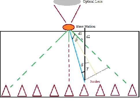
[image:2.595.313.556.505.686.2]In our proposed system a transmitter consist of an Office and laser transmitter. Office processes centrally and distributes the optical signal to a number of access points via an optical fiber feeder network. The Central Office also acts as a gateway to the external network. In the access point, the fiber transmitter is incorporated with a localization function to provide ubiquitous coverage over a 12 × 12 × 10foot room. With the localization information, a comparatively wider divergent beam is employed to cover that user’s position and its surrounding areas. Therefore high speed data transmission using direct LOS link with limited mobility can be provided. When the user moves out of that area, the user’s position can be identified by the localization system, the signal light is then directed to the new position. It gives mobility over the entire room. The redirection of signal is realized by the proposed ceiling mounted fiber transmitter, as shown in Fig. 1.
Fig – 1: System Geometrical Structure
© 2017, IRJET | Impact Factor value: 5.181 | ISO 9001:2008 Certified Journal
| Page 2142
optical Tx/Rx (i.e. ~ 4 m above the ground level), could be tilted by an angle θ1/2+δ represented by γ along the horizontal plane so that it points towards the optical Rx. (d2) is the horizontal separation distance between BS and the shortest coverage point C, which can be varied in order to estimate the transmitter’s beam divergence angle θ. (d1) is fixed at 1 m (BS separation from the track), δ is the coverage angle at the longest point B and β is the coverage angle at the shortest point C. Using a simple geometry , and for ΔACD and ΔABD respectively, we have
and .The estimated transmitter
beam divergence angle can be written as
(1)
Hence, based on the position of the BS and the effective coverage length, the beam divergence angle can be approximated. The optical beam radius of a Gaussian beam is given as [15]:
[ ( ) ] (2) wherewo is the beam waist of the laser source at the transmitter, z is the axis of propagation and 𝝺 is the operating wavelength of the optical source.
Performance of the system is analyzed in the terms of bit error rate. The BER can be evaluated as
BER = Q√ (3) Where Q = and SNR is signal to noise ratio at receiver
SNR =
(4) Where R is responsivity and is total noise including
shot noise, thermal noise and background noise.
The noise source at the detector is the combination of the shot noise, the thermal noise and the background noise. The typical value for the background radiation used is 10 μW. The total noise variance can be written as:
(5)
where , and is the variance due to shot noise,
thermal noise and the background noise is received power.
= (6)
Where r is data rate, is transmitted power, is the
collection area at receiver. is optical beam radius.
= * ( )+⁄ (7)
Where is the beam waist of the laser source at the transmitter, z is the axis of propagation and 𝝺 is the operating wavelength of the optical source.
(8)
The FOV of the receiver using the optical concentrator is given by
(9)
whereAcollis the effective light collection area of the receiver and Adetis the area of the photodetector.
nis the refractive index of an optical concentrator and ψcis the half-angle FOV of the receiver after the lens.
4. RESULTS & DISCUSSION
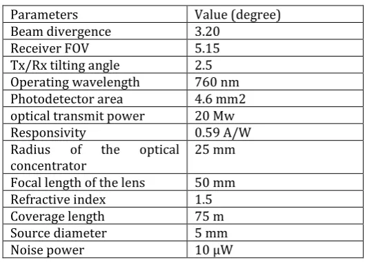
Wireless optical system parameters are shown in table 1.
Table – 1: System Parameters
Parameters Value (degree)
Beam divergence 3.20
Receiver FOV 5.15
Tx/Rx tilting angle 2.5
Operating wavelength 760 nm
Photodetector area 4.6 mm2
optical transmit power 20 Mw
Responsivity 0.59 A/W
Radius of the optical
concentrator 25 mm
Focal length of the lens 50 mm
Refractive index 1.5
Coverage length 75 m
Source diameter 5 mm
Noise power 10 μW
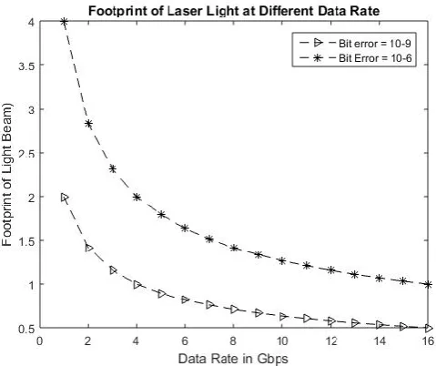
[image:3.595.301.566.185.375.2]In this paper footprint of laser transmitter is measured at different data rates from 1GHz to 16GHz. As data transmission rate increases area covered by laser light decreases. Output is shown in table2.
Table – 2: BER at different Data Rates S.
No. Data Rates (Gbps) BER = 10^-6 BER = 10^-9
1 2 4.0000 2.0000
2 3 2.8284 1.4142
3 4 2.3094 1.1547
4 5 2.0000 1.0000
5 6 1.7889 0.8944
6 7 1.6330 0.8165
7 8 1.5119 0.7559
8 9 1.4142 0.7071
9 10 1.3333 0.6667
10 11 1.2649 0.6325
11 12 1.2060 0.6030
© 2017, IRJET | Impact Factor value: 5.181 | ISO 9001:2008 Certified Journal
| Page 2143
Fig – 2: Footprint of Laser Beam at different Data Rates [image:4.595.321.552.144.337.2]To analyze the performance of optical wireless system bit error rate at the receiver is calculated at different footprint is calculated and compared at different data rates. BER is calculated at 10Gpbs and 12.5 Gbps and plotted on fig. 3. BER comparison table is shown below in table 3.
Table - 3: Comparison of BER vs Footprint at different Bit Rates
S. No. Foot Print BER at
10Gbps BER at 12.5 Gbps
1 0.8 -15.08 -9.8
2 1.0 -12.22 -7.9
Fig – 3: Footprint of Laser Beam at different Data Rates
From fig.3 it can be observe that as foot print increases bit error rate also increases and with increase in data rate,ber increases drastically.
Finally bit error rate is calculated at different point at perpendicular distance from line of sight of beam and results are plotted on fig. 4.
Fig – 4: Footprint of Laser Beam at different distance
[image:4.595.23.565.431.689.2]From fig. 4 it can be observe that bit error rate increases as receiver became away from line of sight. Values of BER is compared and listed in table 4.
Table – 4: BER at variable distance S. No. Distance from
line of sight BER at Bit rate = 10Gbps
BER at Bit rate = 12.5Gbps
1 1 -23 -21.9
2 5 -19.4 -17.95
3 10 -17.2 -15.6
4 20 -13.34 -12.3
5 30 -11.8 -10
6 40 -10.3 -9
7 50 -9 -7.8
5. CONCLUSIONS
[image:4.595.32.295.437.687.2]© 2017, IRJET | Impact Factor value: 5.181 | ISO 9001:2008 Certified Journal
| Page 2144
REFERENCES
[1] F. R. Gfeller and U. Bapst, “Wireless in-house data communication via diffuse infrared radiation,” Proc.IEEE, vol. 67, no. 11, pp. 1474–1486, Nov. 1979. [2] J.M. Kahn and J. R. Barry, “Wireless infrared
communications,” Proc. IEEE, vol. 85, no. 2, pp. 265– 298, Feb. 1997.
[3] J. M. Kahn, J. R. Barry, M. D. Audeh, J. B. Carruthers, W. J. Krause, and G.W. Marsh, “Nondirected infrared links for high-capacity wireless LANs,” IEEE Personal Commun., vol. 1, no. 2, pp. 12–25, Aug. 1994.
[4] D. C. O’Brien and M. Katz, “Optical wireless communications within 4th-generation wireless systems,” J. Opt. Netw., vol. 4, no. 6, pp. 312–322, May 2005.
[5] H. L. Minh, D. C. O’Brien, G. Faulkner, O. Bouchet, M. Wolf, L. Grobe, and J. Li, “A 1.25 Gb/s indoor cellular optical wireless communications demonstrator,” IEEE Photon. Technol. Lett., vol. 22, no. 21, pp. 1598– 1600, Nov. 1, 2010.
[6] Ke Wang, Ampalavanapillai Nirmalathas, Christina Lim, and E fstrations S kafidas, “High-Speed optical
wireless communication system for indoor
applications.” IEEE Photonics Technology Letters, vol. 23, No. 8, April 15, 2011.
[7] J. Fadlullah and M. Kavehrad, “Indoor high bandwidth optical wireless links for sensor networks,” J.Light w. Technol., vol. 28, no. 21, pp. 3086–3094, Nov. 1, 2010. [8] K. Wang, A. Nirmalathas, C. Lim, and E. Skafidas,