Automation of a Prosthetic Limb using Shared Control of Brain
Machine Interface and Vision Guided Robotics
Aparna Justin
1, Sandra S Kurian
2, Aswathy R
3, S S Rijo Steffin
4, Annie P Oommen
51-4B.Tech, Dept. of Electrical and Electronics Engineering, Mar Athanasius College of Engg., Kothamangalam, Kerala-686666, India
5Professor, Dept. of Electrical and Electronics Engineering, Mar Athanasius College of Engg., Kothamangalam, Kerala-686666, India
---***---Abstract -
Brain Machine Interface (BMI), , also termed asDirect Neural Interface (DNI), or Brain Computer Interface (BCI) is a direct communication pathway between an enhanced or wired brain and an external device. BMIs are often directed at researching, mapping, assisting, augmenting, or repairing human cognitive or sensory motor functions. Brain-machine interfaces (BMIs) offer great potential for restoring upper limb function. This project aims to automate an artificial (or prosthetic) limb, particularly for amputees, subjects suffering from local paralysis and even quadriplegics, using Brain Machine Interface (BMI) technology. However, grasping objects is a complicated task and the signals extracted from the brain may not always be capable of driving these movements reliably. Vision-guided robotic assistance is one possible way to improve BMI performance. We describe a method of shared control where the subject controls a prosthetic arm using a BMI and receives assistance with respect to positioning the hand with precision when it approaches an object.
Key Words: Brain Machine Interface (BMI), Electroencephalogram (EEG) signals, Vision Guided Robotics (VGR), Simultaneous Localization And Mapping (SLAM) algorithm
1. INTRODUCTION
The automation of a prosthetic limb using BMI is hindered by various limitations which negatively impact the system performance. The BMI user has limited ability to control the robotic arm near an object. As with natural grasping, the user must be able to determine how to optimally position the hand to grasp the object for the intended action. Currently, BMIs for arm control doesn’t provide sensory feedback for the system, which may impair the normal grasping process. Another potential barrier to optimal performance is that the visual feedback that the user receives is of his own arm rather than the robotic arm to be controlled, which may introduce sensory conflicts. Intelligent, vision-guided robotic assistance is one way to improve BMI performance during grasping.
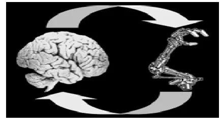
Fig -1: Concept of BMI
2. BRAIN MACHINE INTERFACE
Brain Machine Interface (BMI) or Brain Computer Interface (BCI) is a device set up mechanism that translates neuronal information into commands capable of controlling external software or hardware such as a computer or a robotic arm. BMIs are often used as assisted living devices for individuals with motor or sensory impairments. For eg: a quadriplegic (paralysed from neck down) or an amputee or partially paralysed person thus experiencing restoration of limb function via BMI automated Prosthetic Limb. Here subjects will be controlling a prosthetic limb via Electroencephalo Gram or EEG waves.
2.1 EEG SIGNAL CHARACTERISTICS
Current EEG devices measure potential differences on several electrodes placed on the head of the subject and digitize it for further analysis. Thus, EEG can be seen as a multi-variate time series. EEG signals are very feeble in magnitude, in range of fractions of volts even for the strongest signals and thus the system deployed must be able serve two functions:
[image:1.595.324.542.225.356.2]to also see that a person's simple thought with no seriousness shouldn't translate into an action. So the BMI operated headset has to arrive at a compromise between the above two mentioned factors. So ideal flow of dendrite fluid between two dendrites at the rate ranging from 0.75 to 0.92 on a scale of 1 should be considered as a standard for healthy level and societal acceptance for a BMI system to even operate.
2)Since the detected voltages are minute, the raw data extracted must be amplified version of actual signals recieved for better comprehension of the EEG wave output of the subject under study. The EEG signals of each person is a unique set of patterns. So if the signal pattern that is actually required is not amplified then it will read as a distorted signal and the action won't be executed due to lack of acknowledging this input as the actual input.
[image:2.595.335.534.311.418.2]It as an established fact that an if-else algorithm is used alongside Fuzzy Clustering mathematical model to make the required set of relevant EEG patterns more discrete than the redundant set of unwanted signals i.e, If the waves detected are within the given set of acceptance, the limb is automated.
Fig -2: EEG Signal Waveforms
2.2 FLOW OF CONTROL IN A BMI OPERATED SYSTEM
[image:2.595.56.271.377.507.2]The basic Block Diagram of BMI algorithm on how to translate EEG into useful grasping patterns for reference has been shown in Figure 3.
Fig -3: Capturing of EEG signals to formulate useful grasping Patterns
The EEG signals of the subject under study are grasped from different cortical points mapped. Since the signals are feeble in nature, they are amplified and by Fuzzy mean clustering, the relevant set of signals with most amount of similarities in traits is selected. This signal set is smoothened; unwanted noises are removed and converted into an understandable format. The relevance of these patterns to execute the required action is estimated or compared with reference signals stored and if relevant, the motoring action is executed.
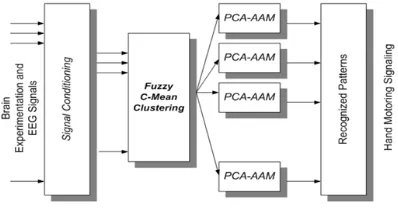
[image:2.595.41.282.609.742.2]The Brain Machine Interface coding Algorithm has been shown in Fig-4. The EEG signals received are conditioned to obtain waves that can be comprehended in a recognizable format. Then using Fuzzy C-Mean clustering, the relevant data sets are set and are set as reference using PCA-AAM . These patterns actually correspond to a particular action to be executed.
Fig -4: BMI Coding Algorithm
The decoding algorithm is shown in Fig-5. Raw EEG signals received from the subject are compared with the reference signals and based on the similarity, the motoring action will accordingly be executed if required.
2.3 LIMITATIONS OF BMI
Solitary application of BMI faces limitations, which have been elucidated below:
1) Calibration error: Say a person is thinking of grasping an object. He or she is only visualizing the distance between him or her and the object and not between the limb and the object if the limb is far from the body. So the limb will end up grasping the wrong object or even nothing due to wrong distance input.
3. VISION GUIDED ROBOTICS
A Vision Guided Robot (VGR) system is basically a robot fitted with one or more cameras used as sensors to provide a secondary feedback signal to the robot controller to more accurately move to a variable target position. Recent studies have shown that brain-machine interfaces (BMIs) offer great potential for restoring upper limb function. However, grasping objects is a complicated task and the signals extracted from the brain may not always be capable of driving these movements reliably. Vision-guided robotic assistance is one possible way to improve BMI performance. As with natural reaching, the user must determine how to optimally position the hand to grasp the object for the intended action. Currently, BMIs for arm control do not provide somatosensory feedback for the user, which may impair the normal grasping process. Finally, another potential barrier to optimal performance is that the visual feedback that a BMI user receives is of a robotic arm rather than their own hand, which may introduce sensory conflicts.
3.1 SLAM ALGORITHM
Simultaneous Localization and Mapping or SLAM Algorithm is used to trace the relative changes in the odometry of the object under study (in our case, to be grasped). SLAM consists of multiple parts; Landmark extraction, data association, state estimation, state update and landmark update. The outline of flow of control for a SLAM algorithm operated system has been shown in figure-5.
Fig -5: Overview of SLAM Algorithm
This visual data is associated or compared with images of
reference landmarks already saved. Then the either of the following situations are possible:
(i) There has been slight change in the position of the landmarks thus signifying relative motion between the object and the environment from its initial position; (ii) A new landmark is showing significant presence in repeated scans of the environment;
(iii) Both of the above situations;
(iv) There hasn't been a change in the landamarks of the environment.
In either way, the odometry data of the system will be fed to the Extended Kalman Filter if there is a noted change. An EKF (Extended Kalman Filter) is the heart of the SLAM process. It is responsible for updating where the robot thinks it is based on these features. These features are commonly called landmarks. The EKF keeps track of an estimate of the uncertainty in the robots position and also the uncertainty in these landmarks it has seen in the environment. When the odometry changes because the robot moves the uncertainty pertaining to the robots new position is updated in the EKF using Odometry update. Landmarks are then extracted from the environment from the robots new position. The robot then attempts to associate these landmarks to observations of landmarks it previously has seen. Re-observed landmarks are then used to update the robots position in the EKF. Landmarks which have not previously been seen are added to the EKF as new observations so they can be re-observed later.
The mathematical computation is done using the Jacobian Measurement Model based matrix formation method. The Jacobian of the measurement model is closely related to the measurement model, of course. The measurement model defines how to compute an expected range and bearing of the measurements (observed landmark positions).
3.2 SHARED CONTROL USING BMI AND VGR
The Shared control of a limb using BMI and VGR has been showcased in the figure-6.
The switch represents the situation when the Limb is attached to your body, thus nullifying the need of VGR. The BMI command for a motoring based grasping action is issued. Using BMI coding and decoding algorithm implementing Fuzzy C-Mean Clustering as discussed earlier, the most refined command is extracted and sent to the controller. Parallely the odometry changes or prevalent conditions are also noted and studied using the VGR system via SLAM algorithm as discussed earlier and the odometry data is also fed to the controller.
data of which is again sent to the controller. Thus, its a repeated feedback process like a basic closed loop control system, thus improving the performance of the system due to changing conditions of environment and/or input signals.
Fig -6: Automation of a Robotic Limb via Shared Control of BMI and VGR
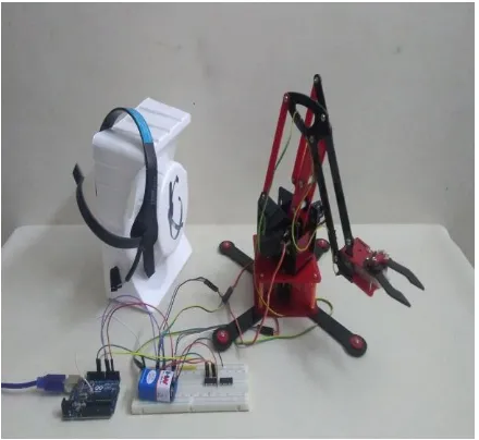
4. EXPERIMENTAL SETUP
The figure-7 summarizes the hardware realisation of the aim of this Project. A Robotic Limb was automated using Brain Machine Interface (BMI). With the established limitations based on odometric calculation to position the arm, based on implementing BMI alone, Shared Control via additional incorporation of Vision Guided Robotics (VGR) was performed. The improvement in the performance of the robotic limb was thus observed and hence the aim of the project was fulfilled.
Fig -7: Experimental setup of the project
3. CONCLUSIONS
The combination of BMI and computer vision-based grasping creates a system that can allow people without use of their arms to control a robotic prosthetic to perform functional tasks in cases where neither technology would be sufficient on its own. The BMI provides the user with high-level control of the pace and goals of the arm movements. The computer vision system helps with the details of the movement, ensuring a secure grasp in the presented cases, but also by identifying how to act on a specific object based on its shape. Balancing the control between the user and the automated system will provide high performance while ensuring that the user feels the device is reliable and responsive to their commands in a variety of situations. As both technologies continue to improve, robotic prosthetic control makes it both easier and more useful for the people who need it.
REFERENCES
[1] Elena Mainardi, Angelo Davalli; “Controlling a prosthetic arm with a throat microphone”; Proceedings of the 29th Annual International Conference of the IEEE EMBS Cité Internationale, Lyon, France August 23-26, 2007
[2] Harold Martin, Jaime Donaw; “A Novel Approach of Prosthetic Arm Control using Computer Vision, Biosignals, and Motion Capture”; 2014 IEEE Symposium on Computational Intelligence in Robotic Rehabilitation and Assistive Technologies (CIR2AT)
[3] Dianchun Bai, Chunyu Xia, Junyou Yang and Shouxian Zhang ; “Shoulder Joint Control Method for Smart Prosthetic Arm Based on Surface EMG Recognition”; Proceedings of the IEEE International Conference on Information and Automation Ningbo, China, August 2016
[4] Kapil D. Katyal , Matthew S. Johannes; “A Collaborative BCI Approach to Autonomous Control of a Prosthetic Limb System”; 2014 IEEE International Conference on Systems, Man, and Cybernetics October 5-8, 2014, San Diego, CA, USA
[5] Søren Riisgaard, Morten Rufus Blas ;"SLAM for Dummies : A Tutorial approach to Simultaneous Localization and Mapping"
[6] John E. Downey, Jeffrey M. Weiss, Katharina Muelling, Arun Venkatraman, Jean-Sebastien Valois,Martial Hebert, J. Andrew Bagnell, Andrew B. Schwartz, and Jennifer L. Collinger; " Blending of brain-machine interface and vision-guided autonomous robotics improves neuroprosthetic arm performance during grasping"; Downey et al. Journal of NeuroEngineering and Rehabilitation (2016)
[image:4.595.52.272.545.747.2]and Pharmacolgy, Brain Center Rudolf Magnus, University Medical Center Utrecht, Heidelberglaan 100, 3584 CG Utrecht, The Netherlands; Department of Neurology and Neurosurgery, Brain Center Rudolf Magnus, University Medical Center Utrecht, Heidelberglaan 100, 3584 CX Utrecht, The Netherlands; 12th August 2013
[8] Jack DiGiovanna, Babak Mahmoudi, Jose Fortes;” Coadaptive Brain–Machine Interface via Reinforcement Learning”; IEEE TRANSACTIONS ON BIOMEDICAL ENGINEERING, VOL. 56, NO. 1, JANUARY 2009