© 2016, IRJET | Impact Factor value: 4.45 | ISO 9001:2008 Certified Journal | Page 1
SAP2000 PROGRAMS
Abdul Ahad FAIZAN
Master Student, Dept. of Civil Engineering, Sakarya University, Sakarya, Turkey
---***---Abstract -
Frame structures are the structures which arehaving the combination of beam, column resists the lateral and gravity loads. Many programs are available for analyzing of these systems. The aim of this study is to analyze the proposed plane frame system by using MATLAB computer programming language and SAP2000 by the basic idea of matrix stiffness method and comparing the results that how are the results will be near. Through this analysis we could find the joint displacements, element forces and moments in each element. All of the analytical results (Joint displacements member element forces, moments and rotations) that obtained from MATLAB programming language are satisfied with the results obtained from SAP2000 software.
Key Words: MATLAB Programming Language,
SAP2000, Plane Frame, Matrix Stiffness Method.
1. INTRODUCTION
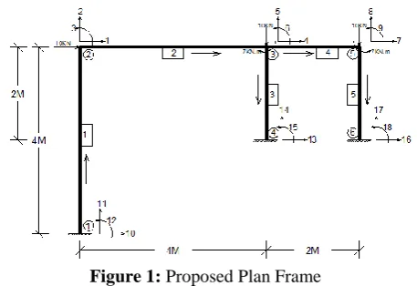
Framed buildings are building structures formed by the framed elements usually in the form of columns and beams, as well as further strengthened as necessary by the introduction of rigid floor membranes and external walls. Over the years, frame systems have been increasing popular because of their light weight, pleasing appearance, high strength, easy fabrication and rapid erection. From economic point of view, frame can sustain considerable loads and behave favorably by using small amount of materials. Many structural truss applications are found all over the world covering stadiums, exhibition centers, factories, airplane hangars, bridges and many others. The proposed plane frame structure analyzed in this study is 4m and 2m in span length with 4m height, 3 joint loads and two moments. The module of elasticity of steel (E) is 29000ksi and the area of cross section (A) is 2.85E-04m-sqr-m. In this study the proposed plan frame was analyzed by programing language MATLAB and SAP2000 software and then compared the results. The analyzed results include joint displacements, member’s axial forces, element moments and rotations, which is the results from both programs has got approximately the same, namely all of the
analytical results obtained from MATLAB
programming language are nearly with the results obtained from SAP 2000 software. MATLAB is useful in illustrating how to program matrix stiffness method due to the fact that it allows one to very quickly code numerical methods and has vast predefined mathematical library. The stiffness method is a very effective method for analyzing structures using a computer. The stiffness method can be used to analyze both statically determinate and indeterminate structures. Also, the stiffness method yields the displacements and forces directly,
whereas with the flexibility method the
[image:1.595.321.550.433.590.2]displacements are not obtained directly. By using this method it is much easier to make matrix formulas for computer. [1]
Figure 1: Proposed Plan Frame
2. METHODOOGY
The proposed plane frame is analyzed by stiffness method. Stiffness method of structural analysis is a matrix method of structural analysis. The stiffness method can be used to analyze both statically determinate and indeterminate structures, the stiffness method yields the displacements and forces directly, and furthermore, it is generally much easier to formulate the necessary matrices for the computer operations using the stiffness method. The basic idea of matrix stiffness method used in this analysis can be applied to develop programming for any frame
© 2016, IRJET | Impact Factor value: 4.45 | ISO 9001:2008 Certified Journal | Page 2 structure. Also can determine and get element forces,
displacements, joint reactions in nodes and more analytical and numerical results through this method.
2.1 Displacement Transformation Matrix
A Global coordinate displacement which is showing by can creates local Coordinate displacement which showing by and [2]
= , =-
And are the angles which element makes with x
and y axis. A rotation about z causes a corresponding rotation about Thus,
=
If the be the global displacement in X direction, and in Y direction and a rotation in result the transformation equations are as following.
= , =
= , =
=
If and the superposition of
displacement in matrix form will be as following [2]
[
]
=
[
][
]
(1)
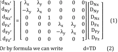
Or by formula we can write d=TD (2)
Where T transforms the six global x, y, and z displacements D into the six local displacements d. Hence T is referred to as the displacement transformation matrix.
2.2 Force Transformation Matrix
The internal member load which is showing by q and deformation which is showing by d should transfer from local coordinates to global coordinates from and that is why weneed the transformation matrices. The local coordinate is x’, y’, z’and the global coordinate is x, y, z. Also , axial loads and , shear loads, and , are bending moments.
The steps are similar with the previous section namely displacement transformation matrix, and in here we can determine how to transform the load components from local to global coordinates.
= =
= - =
If =
= =
= =
=
If and the equations in matrix
form can be write as following
[
]
=
[
][
]
(3)
Or by formula we can write Q = (4)
Where transforms the six member loads
expressed in local coordinates into the six loadings expressed in global coordinates
.
2.3 Member Global Stiffness Matrix
By considering of previous sections to determine the stiffness matrix for a member that relates the global loadings Q to the global displacements D. To do this, substitute d = TD into q = d we will have;
q = TD (5)
By substituting this result into Q = q we will have; Q= T D (6)
Or Q= k D
[image:2.595.37.273.474.578.2]
Where k= T (7)
© 2016, IRJET | Impact Factor value: 4.45 | ISO 9001:2008 Certified Journal | Page 3 In Fig2, k represents the global stiffness matrix for the
member [2]
For known external loads and displacements ( , ) and unknown loads and displacements by the seem of equation Q= KD we will have;
=K21Du+K22Dk (8)
=K11Du+K12D (9)
Where and are known external load and
displacement and , are unknown external load and displacement.
3. RESULTS AND DISCUSSIONS
[image:3.595.358.510.143.246.2]After all the input data required for the analysis of the plane frame have prepared run in MATLAB programming language. Displacements at each joint, member axial forces, moments and rotations are obtained as results. [3] The proposed plane frame is also analyzed with SAP2000 software to compare the results obtained from the MATLAB programming language. Following tables show the comparison of the results to see whether difference between results obtained from MATLAB programming and SAP2000 software is significant or not. The analytical results of the plane frame are shown in the following tables.
Figure 3: Plane Frame Figure 4: Deformed Shape
Table-1: Comparison of Joint Displacements
Joint No
Joint Displacement (m)
SAP2000 MATLLAB
U1 U3 U1 U3
1 0 0 0 0
2 0.007984 0.000026 0.008121 0.0000265
3 0.007918 -0.000039 0.008011 -0.00004
4 0 0 0 0
5 0.007899 -0.000114 0.008098 -0.000115
6 0 0 0 0
Table-2: Joint Displacements Diff
Difference(m) Difference (%)
U1 U1 U1 U3
0 0 0 0
0.000137 0.000137 1.687 1.887
0.000093 0.000093 1.161 2.5
0 0 0 0
0.000199 0.000199 2.457 0.869
0 0 0 0
From Table 1 and 2 it can be seen that the difference between displacement at joint 2, 3 and 5 in x direction is 1.37E-04, 9.3E-05 and 1.99E-04 and in joint 1, 4 and 6 is 0. Also the difference between displacement at joint 2, 3 and 5 in y direction is 5E-07, 1E-06 and 1E-06. It is obviously showed that the displacement from MATLAB programming is approximately same with the results from SAP 2000. [4]
Table-3: Comparison of Member Axial Forces
Element Joint No
Sap2000 MATLAB
F1 F3 F1 F3
KN KN KN KN
1-1 -0.678 -1.876 -0.681 -1.891
1-1 0.678 1.876 0.681 1.891
2-1 9.322 -1.876 9.576 -1.891
2-1 -9.322 1.876 -9.576 1.891
3-1 3.825 -5.608 3.921 -5.612
3-1 -3.825 5.608 -3.921 5.612
4-1 5.497 -6.268 5.621 -6.311
4-1 -5.497 6.268 -5.621 6.311
5-1 5.497 -16.268 5.531 -16.456
[image:3.595.39.270.440.597.2]5-1 -5.497 16.268 -5.531 16.456
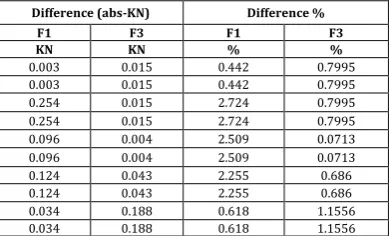
Table-4: Member Axial Forces Difference
Difference (abs-KN) Difference %
F1 F3 F1 F3
KN KN % %
0.003 0.015 0.442 0.7995
0.003 0.015 0.442 0.7995
0.254 0.015 2.724 0.7995
0.254 0.015 2.724 0.7995
0.096 0.004 2.509 0.0713
0.096 0.004 2.509 0.0713
0.124 0.043 2.255 0.686
0.124 0.043 2.255 0.686
0.034 0.188 0.618 1.1556
0.034 0.188 0.618 1.1556
[image:3.595.337.532.583.701.2]© 2016, IRJET | Impact Factor value: 4.45 | ISO 9001:2008 Certified Journal | Page 4 is 0.034. The minimum difference is 0.0015 at
member 1. The differences of axial forces of other members are between 0.254 to 0.0034 in x direction and 0.015 to 0.188 in y direction. It can be said that the member forces obtained from MATLAB programming are acceptable. [5]
Table-5: Element Momemnts
Table-6: Rotation of Frame
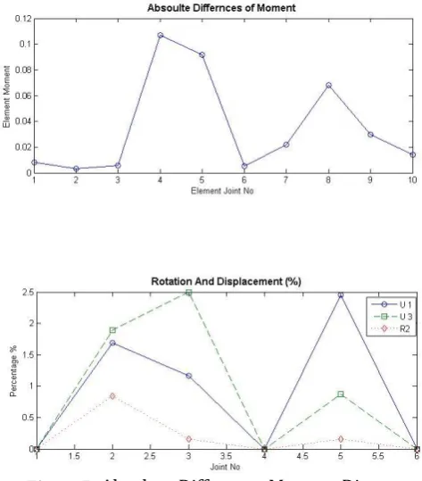
Table 5 and 6 shows that the element moments and rotation resulted from the developed program are not much different from SAP2000. The maximum difference of moments is 2.159% and the maximum
rotation is 0.84% so it can be
Figure 5: Moment Diagram of Proposed Plane Frame
Figure 6: Percentage Difference Moment Diagram
Figure 7: Absolute Difference Moment Diagram
Figure 8: Rotation and Displacement Diagram
Figure 9: Percentage Force Difference Diagram
Element Joint No
SAP MATLAB Difference Difference
M M Moment Diff (abs) Moment Diff
KN.M KN.M KN.M %
1-1 -2.771 -2.779 0.008 0.287
1-1 -2.656 -2.659 0.003 0.112
2-1 2.656 2.662 0.0059 0.225
2-1 4.847 4.954 0.1069 2.159
3-1 -6.439 -6.531 0.0919 1.408
3-1 -8.859 -8.864 0.005 0.056
4-1 8.591 8.613 0.022 0.255
4-1 3.945 4.013 0.068 1.694
5-1 -10.945 -10.975 0.0299 0.273
5-1 -11.042 -11.056 0.0139 0.126
Joint No Rotation (Radian)
SAP MATLAB Diff (abs) Diff (%)
1 0 0 0 0
2 0.000118 0.000119 0.000001 0.84
3 0.001246 0.001248 0.000002 0.16
4 0 0 0 0
5 0.00005 0.00006 0.00001 0.16
[image:4.595.316.553.257.527.2] [image:4.595.38.285.566.692.2]© 2016, IRJET | Impact Factor value: 4.45 | ISO 9001:2008 Certified Journal | Page 5
Figure 10: Absolute Force Difference Diagram
4. CONCLUSION
With the increasing computer technology, the development of computer programming capable of providing any Frame analysis results significant improvements to Frame design. This paper has discussed the analysis of plane Frame by using computer programming language, MATLAB and SAP2000. The basic idea of matrix stiffness method used in this analysis can be applied to develop programming for any truss structure. The developed plane truss analysis program gives the displacements at each node directly. The member forces of statically determinate or indeterminate plane truss can be determined effectively by using this plane Frame analysis software. The comparison between results produced from MATLAB programming and SAP2000 software shows member axial forces, 0.254 (2.724%) in x direction and 0.188 (1.156%) is the maximum difference between axial forces in y direction from the MATLAB programming and SAP2000 software, and 0.0004 (0.0713%) at member 1 and 4 is the minimum difference. According to the results obtained, the average of percent difference of X-direction forces (F1) and the Y-direction forces (F3) and the moment (M) is 1.709%, 0.702% and 0.659%. Also the maximum differences between MATLAB and SAP2000 in joint displacements (U1,U3) is 1.887% and the maximum differences between rotation (R) is 0.84% which we can say the results are nearly the same.Therefore, all of the analytical results (Joint
displacements,Element moments and Rotations)
obtained from MATLAB software are satisfied with the results obtained from SAP2000 software. Also It can be concluded that the developed program with
MATLAB code presented in this paper can be applied
for any plane Frame structure. Any plane frame structure can be analyzed and solved with this program effectively.
REFERENCES
[1] William McGire, Richard H.Gallagher and Ronald D.Ziemian, Matrix Structural Analysis, 2nd Edition, John Willy and Sons, Inc.
[2] R.C Hibbeler, Structural Analysis, 8th Edition
[3] Aslam Kassimali, Matrix Analysis of Structures, 2nd Edition, Southern Illinois University-Carbondale, Cengage Learning.
[4] Computers and Structures, Inc. SAP2000 vi17