© 2018, IRJET | Impact Factor value: 6.171 | ISO 9001:2008 Certified Journal | Page 15
COMPARATIVE STUDY OF PERFORMANCE OF 60 STOREY STEEL
BUILDINGS WITH EXO-SKELETON, FRAMED TUBE AND CONVENTIONAL
STRUCTURAL SYSTEMS UNDER DYNAMIC LOADING
Hirenkumar P. Makwana
1, Pravin L. Hirani
2, Narendra R. Pokar
31
P.G. Student, Department of Civil Engineering, HJD ITER, Kera-Kutch, Gujarat, India
2Assistant Professor, Department of Civil Engineering, HJD ITER, Kera-Kutch, Gujarat, India
3
Structure Engineer, Bhuj-Kutch, Gujarat, India
---***---Abstract -
High rise steel buildings with Exoskeletonstructural system, Framed tube structure system and Conventional structure system under dynamic loading for 60 storey are taken for the analysis. Earthquake zone III (Kolkata) & zone V (Darbhang) and all soil conditions are considered to compare the results in terms of time period, storey displacement, storey drift and storey shear. For dynamic earthquake and dynamic wind analysis response spectrum method (IS 1893-2002) and gust factor method ( IS 875-1987 part 3)are used respectively in ETABS V16 software. For steel design IS 800-2007 is considered.
Key Words:Exoskeleton system, Framed Tube system, Conventional system, Dynamic analysis, Gust Factor method, Response spectrum method, Time period, Storey displacement, Storey drift, Storey shear , ETABS.
1. INTRODUCTION
The nature of building perimeters has more structural significance in tall buildings than in any other building type due to their tallness, greater vulnerability to lateral forces occurs. Thus, it is quite desirable to concentrate on lateral load-resisting systems on the perimeter of tall buildings to increase their structural depth and resistance to lateral loads.
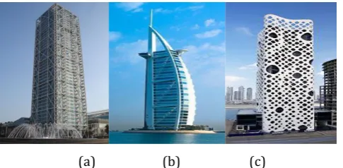
An “exoskeleton” is basically a Greek word, meaning “outer skeleton‟. It is the external skeleton that protects an animal’s body as per zoology. In civil engineering, it is an external supporting structure that resist lateral loading.
(a) (b) (c)
Fig -1: Exoskeleton structure (a) Hotel De Las Artes, Spain (b) Hotel Burj Al Arab, Dubai (c) O-14Business Bay, Dubai
In Framed tube structure system columns are closely spaced at the perimeter and columns joined by
beams which resist lateral loads. This creates tube as continues perforated chimney. This type of structure is constructed up to 100 stories.
Fig -2: Framed Tube structure (a) Brunswick Building, Chicago (b) De Witt Chestnut Apartment, Chicago (c)
World Trade Centre (1973-2001)
2. Research Significance
In high rise buildings it is necessary to analyze dynamic loads. As the height of the building increases, lateral loads like earthquake and wind loads acting on building become more venerable so it is necessary to analyze the lateral loads.
In this paper three systems are compared in terms of time period, displacement, drift, and shear. To analyze the lateral loading two locations Kolkata and Darbhang are considered. The objective of this study is to find out which system is better to resist dynamic earthquake and dynamic wind load
3. Modelling and Analysis
3.1 Building Configuration
For the comparison of exoskeleton, framed tube and conventional structure systems a square plan of 36 x 36 m having typical storey height and bottom storey height of 3m is considered. The total structure height is 180 m. Fe 345 material having weight density 76.9729 kN/m3 is selected.
[image:1.595.340.556.277.381.2] [image:1.595.37.280.598.717.2]© 2018, IRJET | Impact Factor value: 6.171 | ISO 9001:2008 Certified Journal | Page 16 (a) (b)
Fig -1: Column details (a) Interior column C1,(b) Exterior column C2
3.2 Model Preparation
Modelling is done using ETABS v16 software.
Fig -2: Plan, Elevation & 3D view of Conventional system
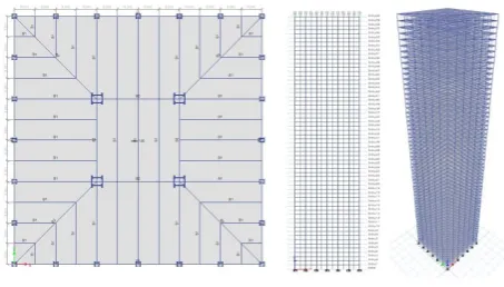
Fig -3: Plan, Elevation & 3D view of Exoskeleton system
Fig -4: Plan, Elevation & 3D view of Framed tube System
3.3 Dynamic analysis methods and Loading Data
Dead Load = 1.5 kN/m2
Live Load = 2.5 kN/m2
Cladding Load = 0.108 kN/m2
3.3.1 Response spectrum method
[image:2.595.43.287.74.200.2]A response spectrum method is straight forward graphical portrayal of unfaltering state reaction for dislodging, speed or quickening of oscillators of fluctuating normal response that are forced into motion by the same base vibration. In this method response of multiple modes of a building is consider for the analysis. The response of a structure can be defined as a combination of modes that in a vibrating string correspond to the “harmonic”. To perform response spectrum analysis, it is necessary to know the earthquake intensity at zone on which the building.
Table -1: Earthquake Loading data
Location Kolkata Darbhang
Zone 3 5
Zone Factor, Z 0.16 0.36
Importance Factor, I 1.2 1.2 Response reduction Factor, R 5 5
Soil Type I,II & III I,II & III
3.3. Gust Factor method
Gust factor method is rational and realistic and it is considered for the computation of dynamic wind loads in the case of very tall frames and structures. It becomes necessary to study the criticality of wind forces in the case of multi-storied frames particularly on more serve wind zones. Here, basic wind speed for Kolkata and Darbhang is 50m/s and 55 m/s respectively. For the dynamic wind analysis terrain category III and class C is consider.
3.3.2.1 Calculation of dynamic wind load
Criteria to satisfy for the requirement of dynamic analysis as per IS 875-1987 part 3
Case1: If height to least lateral dimension ratio > 5.
Table -2: Dynamic wind analysis check case-1
System (m) H (m) D H/D Dynamic analysis
Conv. &
Fram. 180 36 5
= 5 Not Required
[image:2.595.50.277.286.415.2] [image:2.595.308.560.333.435.2]© 2018, IRJET | Impact Factor value: 6.171 | ISO 9001:2008 Certified Journal | Page 17 Hence, Dynamic analysis is not required for 60 storey
structure.
[image:3.595.311.550.340.466.2]Case 2 : If natural frequency (f) < 1.0 Hz.
Table -3: Dynamic wind analysis check case-2
Hence, Dynamic analysis of all models is required to study. Hence, From above two cases it is clear that dynamic analysis is required to study in these models.
As per IS-875-1987 (part-3), (Cl-8.3)
Fz =Cf . Ae . Pz . G
Where, Fz = along wind load on structure at any height z
corresponding to strip area Ae, Cf = force coefficient for the
building= 1.4 (IS 875, part-3, Fig 6A), Ae = effective frontal
area considered for the structure at height z, Ae =108 m2 for
Conventional and Framed tube system and Ae =114 m2 for
Exoskeleton system, Pz = design pressure at height z due to
hourly wind obtained as 0.6Vz2 Where, Vz = design wind
velocity in m/s at height z (m) Vz = Vb . k1 . k2 . k3
Where, Vb = basic wind speed,k1 = Risk coefficient factor =
1.08 (IS- 875,part-3,Table 1), k2= Hourly mean wind speed
factor (IS-875,Part-3, Table-33), k3= topography factor =
1(IS-875,Part-3, CL 5.3.3).
G = Gust Factor (IS-875, Part-3, CL 8.3)
G = 1 + gf . r
Where, gf = peak factor, r = roughness factor, gf.r = Value of
gf.r is obtain from IS-875 part 3= 0.95, B= background factor
and is obtained from IS-875 part-3 Fig-9, Ø = 0 for building height greater than 25 for category 3, S= Size reduction factor 875, Fig-10), β = Damping coefficient=0.0020 (IS-875, Table 34), To find out B
λ = (Cy b) / (Cz h) (IS-875, Fig 9, page-50)
Where,
Cy = lateral correlation constant = 10 (IS-875, page 52), Cz =
[image:3.595.308.555.595.745.2]longitudinal correlation constant = 12 (IS-875, page 52), b = breadth of the structure normal to the wind stream, h = height of the structure, L(h) = a measure of turbulence length scale (IS-875, Fig-9)
Table -4: For value of λ and B
Values of K2, S, E and G are interpolated and from that values Along wind dynamic loads are evaluated for each storey for Kolkata and Darbhang location.
4. Result Analysis
Results obtained from ETABS software in terms of Fundamental time period, storey displacement, storey drift, storey shear are exported to excel to make a charts. Due to symmetry results in X and Y direction are approximately same.
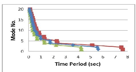
4.1 Fundamental Time Period
Chart -1: Fundamental Time Period
4.2 Storey Displacement
Permissible storey displacement for steel building is H/300. Here, Height of structure H is 180 m therefore maximum permissible limit is 600 mm. Hence, displacements of all models are within permissible limit.
Chart -2: Storey Displacement for Kolkata (zone 3) System H
(m) D (m)
T=0.09 H/√D
f (Hz)
Dynamic Analysis Conv. &
Fram. 180 36 2.7 0.37
< 1 Required Exoskele
ton 180 38 2.63 0.38
< 1 Required
Height,
h(m) L(h)
λ= (Cy.b)/(Cz.h)
B Conv.
& Fram.
Exosk eleton
© 2018, IRJET | Impact Factor value: 6.171 | ISO 9001:2008 Certified Journal | Page 18 Chart -3: Storey Displacement for Darbhang (zone 5)
4.3 Storey Drift
Permissible limit for storey drift is 0.004 times the storey height. Hence all models are within permissible drift criteria.
Chart -4: Storey Drift for Kolkata (zone 3)
Chart -5: Storey Drift for Darbhang (zone 5)
4.4 Storey Shear
Here Maximum storey shear of all systems for earthquake and wind load are represented in form of chart.
Chart -6: Maximum storey shear for Kolkata (zone 3)
Chart -7: Maximum Storey Shear for Darbhang (zone 5)
3. CONCLUSIONS
For the analysis 36m x 36m square regular plan is considered and that is analyzed for dynamic loading using response spectrum method and gust factor method and get results in terms of time period, displacement, drift and shear using ETABS software.
From the results it is observed that,
Exoskeleton system is stiffer than the frame tube and conventional system.
For dynamic earthquake load maximum displacement is in conventional system and it is approximately decreases 47% in Framed tube system and decreases 71% in Exoskeleton system for all soil conditions at both locations.
Displacement due to dynamic wind load at Kolkata is reduced to 41% in framed tube system and 63% in exoskeleton system than conventional system.
Displacement due to dynamic wind load at Darbhang is reduced to 48% in framed tube system and 67% in exoskeleton system than conventional system.
Maximum storey drift of exoskeleton and frametube structure system decreases 67% and 47% respectively for the dynamic earthquake loading and decreases 63% and 49% respectively for dynamic wind loading than the conventional structure system at both direction.
Maximum storey shear of exoskeleton and frame tube structure system decreases 51% and increases 3% respectively for the dynamic earthquake loading and decreases 55% and 5% respectively for dynamic wind loading than the conventional structure system in both direction at both locations.
ACKNOWLEDGEMENT
© 2018, IRJET | Impact Factor value: 6.171 | ISO 9001:2008 Certified Journal | Page 19 Asst. Prof. Pravin L. Hirani and Mr. Narendra R. Pokar. I
would like to thank all faculty members of Civil Engineering Department, HJD ITER for providing all kind of possible help throughout this work. I am extremely grateful to my parents, sister, brother and friends for the support and constant encouragement they have given me throughout the stretch of this work.
REFERENCES
[1] Harish Varsani, Narendra Pokar & Dipesh Gandhi
,“Comparative analysis of exo-skeleton, diagrid and conventional structural system for tall building”, IJAREST, 2015, ISSN(O):2393-9877, ISSN(P): 2394-2444, VOLUME 2,ISSUE 3,c2015
[2] Mir M. Ali & Kyoung Sun Moon,”Structural developments
in tall buildings: current trends and future prospects”, Taylor & Francis, 2011
[3] Abbas Ali Ibrahim & Dr. N. V. Ramana Rao, “A
comparative study between the use of framed shear wall system and framed tube system in tall buildings”, IJMETR,ISSN NO: 2348-4845, VOLUME NO: 2, ISSUE NO: 8, 2015
[4] Iman Mazinani, Mohd Zamin Jumaat, Z. Ismail And Ong
Zhi Chao,” Comparison of shear lag in structural steel building with framed tube and braced tube , Structural engineering and mechanics, ISSN: 1225-4568, VOL. 49, NO. 3
[5] Khushbu Jani, Paresh V. Patel, “Analysis and design of
diagrid structural system for high rise steel buildings”, Elsevier Ltd, Procedia engineering 51, 2015
[6] B. N. Sarath & D. Claudia Jeyapushpa , “Comparative
seismic analysis of an irregular building with a shear wall and frame tube system of various sizes”, IJECS, Volume 4, ISSN:2319-7242, 2015
[7] Jignesh A. Patel, Roshni J. John, “Seismic analysis of
frame tube structure “, IJSER, ISSN:2229-5518, Volume 6, Issue 12, 2015
[8] Mir M. Ali, “Performance characteristic of tall framed
tube building in seismic zones”, WCEE, Paper 1169, ISBN:0080428223
[9] Archana J, Reshmi P R, “Comparative study on tube in
tube structures and tubed mega frames”, IJIRSET, Vol. 5, Issue 8
[10] Mohan K T, Rahul Y ,Virendra Kumara K N, “Analysis of
different forms of tube in tube structures subjected to lateral loads”, IJIRT, Volume 4 Issue 2 , ISSN: 2349-6002, 2017
[11] Asif Hameed, Imran Azeem, Asad-ullah Qazi, Burhan
Sharif and Noor Muhammad Khan, “Drift and cost
comparison of different structural systems for tall buildings”, Pak. J. Engg. & Appl. Sci., Vol. 12, 2013
[12] Bellam Pratheek and Rishit Kar, “Seismic design of
multi-storeyed and multi bay steel building frame”, Pak. J. Engg. & Appl. Sci., Vol. 12, 2013
[13] Ranjitha K. P, Khalid Nayaz Khan, Dr. N. S. Kumar, Syed
Ahamed Raza,”Effect of wind pressure on r.c tall buildings using gust factor method”, IJERT, Vol. 3 ,Issue 7, 2014
[14] IS: 800-2007. General Construction in Steel - Code of
Practice. Bureau of Indian Standard, New Delhi
[15] IS: 1893(Part-I)-2002. Criteria for Earthquake Resistant
Design of Structures. Bureau of Indian Standard, New Delhi.
[16] IS: 875(Part-1)-1987. Code of practice for design loads
(other than earthquake) for buildings and structures, Dead loads, unit weights of building materials and stored materials. Bureau of Indian Standard, New Delhi.
[17] IS: 875(Part-3)-1987. Code of practice for design loads
(other than earthquake) for buildings and structures, wind loads. Bureau of Indian Standard, New Delhi.
BIOGRAPHIES
Hirenkumar P. Makwana P.G. Student,
Department of Civil Engineering, HJD ITER, Kera-Kutch,
Gujarat, India
Mr. Pravin L. Hirani Assistant Professor
Department of Civil Engineering, HJD ITER, Kera-Kutch,
Gujarat, India