© 2018, IRJET | Impact Factor value: 6.171 | ISO 9001:2008 Certified Journal | Page 3669
SEISMIC RESPONSE EVALUATION OF SLOPING BUILDING STRUCTURE
USING BASE ISOLATION
I M Amrutkar
1, Mr. P R Vaidya
2, V G Badgujar
3, H G Desale
4, S A Patel
51,3,4,5
BE students, Dept. of Civil Engineering,
R.H. Sapat College of Engineering, Nashik
Maharashtra, India
2
Assistant Professor, Department of Civil Engineering, R.H. Sapat College of Engineering, Nashik
Maharashtra, India
---***---Abstract –
The base isolation is technique that has beenused to protect the structures from the damaging effects of earthquake. The installation of isolators at the base
increases the flexibility of the building structures. In present study Modeling and analysis RC building is done in SAP2000 software for two cases. The first one is fixed base and the second one is base isolated the building considered for the study represents vertically irregular building on sloping ground. The Lead rubber bearing (LRB) is designed as per UBC 97 code and IS 1893 Part (I) -2002 Seismic response of building was compared with control model without base isolation. The results obtained from analysis one
represented through seismic response parameters such as displacement, storey drift, base shear and maximum forces in interior and exterior column. Due to the presence of isolators the inter storey drift and Base shear observed to be reduced and storey displacement is increased as compared to fixed base structures.
Key Words: Base isolation, sloping ground, Lead rubber
bearing, Equivalent static method, Response spectrum method, etc.
1. INTRODUCTION
The financial development and fast urbanization in uneven district has quickened the land improvement. Because of this, populace thickness in the sloping region has expanded enormously. Along these lines, there is popular and pressing demand for the development of multi-story structures on sloping ground and around the urban areas. A lack of plain ground in also compels the construction activity on sloping ground. Hill buildings are different from those in plains; they are very irregular and symmetrical in horizontal and vertical planes, and torsional coupled. Most of the hilly areas come under seismic zones, in such cases building of the most commonly used lateral load resisting in high rise building. Shear wall has high in plane stiffness and strength which can be used to simultaneously resist large horizontal loads and support gravity loads. For the buildings on sloping ground, the height of columns below plinth level is not same which affects the performance of building during earthquake. Hence to improve the seismic performance of building shear walls play very important role. So the there is need to study the shape and positioning of shear walls on seismic performance of building situated on sloping
ground. Buildings constructed in hilly areas have peculiar structural configurations. Successive floors of such buildings step back towards the hill slope and sometimes, the buildings also set back, lateral stiffness of uphill and downhill side frames. The Torsional behavior of these buildings is much more complex than that of buildings on flat ground due to shifting of centre of stiffness and centre of mass with floor level.
1.1Base Isolation
[image:1.595.312.554.481.675.2]In base isolation technology during earthquake, separating the superstructure or reducing the lateral movements of building superstructure from the movement of ground or foundation. The bearings of base isolation are designed in such a way that they are stiff vertically and flexible horizontally to allow for the difference in lateral movement while still supporting the superstructure. The base isolated structures are different than that of fixed base structure, in which the connection between the superstructure and the foundation are rigid and the superstructure translation in all direction is constrained
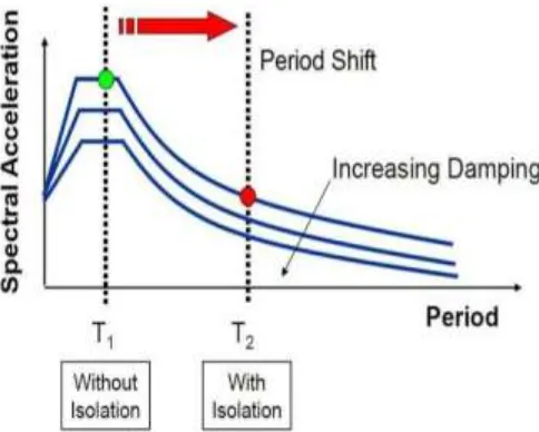
© 2018, IRJET | Impact Factor value: 6.171 | ISO 9001:2008 Certified Journal | Page 3670 The main aim of base isolation is to reduce the earthquake
force produced on building superstructure. To some extent by reducing the superstructure’s spectral acceleration, the reduction in seismic force at superstructure is achieved. By increasing the base isolated structure fundamental period and through damping caused by dissipation energy within bearing the
accelerations are reduced. Lead Rubber Bearing
[image:2.595.43.281.378.534.2]A variety of isolation devices including elastomeric bearings (with and without lead core), frictional/sliding bearings and roller bearings have been developed and used practically for a seismic design of buildings during the last 25 years. Among the various base isolation system, the lead rubber bearing had been used extensively. It consists of alternate layers of rubber and steel plates with one or more lead plugs that are inserted into the holes. Due to lateral forces the lead core deforms, yields at low level of shear stresses approximately 8 to10 Mpa at normal (200c) temperature, so the lead bearing lateral stiffness is significantly reduced. Due to this period of structure increases. One of the features of lead core is that it can recrystalize at normal temperature and will not encounter the problems of fatigue failure under cyclic loadings.
Fig-2: Lead Rubber Bearing with Layers of Rubber and Steel and Lead Core
Basic functions of LRB’s:
Load supporting function: Rubber reinforced with steel plates provides stable support for structures. Multilayer construction rather than single layer rubber pads provides better vertical rigidity for supporting a building.
Horizontal elasticity function: With the help of LRB, earthquake motion is converted to low speed motion. As horizontal stiffness of multilayer rubber bearing is low, strong earthquake vibration is lightened and the oscillation period of the building is increased.
Restoration function: Horizontal elasticity of LRB returns the building to its original position. In LRB, elasticity mainly comes from restoring force
of the rubber layers. After an earthquake this restoring force returns the building to the original position.
Damping Function: Provides required amount of damping that is necessary.
2. METHODOLOGY
It is proposed to study the effectiveness of base isolation technique considering following factor. Comparative assessment of fixed base building with isolated building. Three dimensional analysis of building will be carried out using finite element software SAP. The beam and column are modeled are two nodded line element with 6 DOF at a each node. The slab is modeled using 4 nodded area elements. The study will be carried out in two parts explained below.
MODEL 1:- Fixed base building without base isolation.
MODEL 2:- Building with lead rubber bearing as isolators.
2.1 Modeling of Building
1. Software used for analysis is Sap2000
2. Units used are ‘KN-m’
3. Code provisions as per UBC 1997 and IS 1893 (Part 1)
4. Types of analysis performed are Equivalent Static Analysis &Response spectrum analysis.
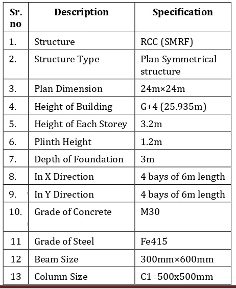
Table-1: Data used for Building Analysis
Sr.
no Description Specification
1. 1 Structure RCC (SMRF)
2. Structure Type Plan Symmetrical structure
3. Plan Dimension 24m×24m
4. Height of Building G+4 (25.935m) 5. Height of Each Storey 3.2m
6. Plinth Height 1.2m
7. Depth of Foundation 3m
8. In X Direction 4 bays of 6m length
9. 9 In Y Direction 4 bays of 6m length 10. 1
0 Grade of Concrete M30 11 Grade of Steel Fe415
12 Beam Size 300mm×600mm
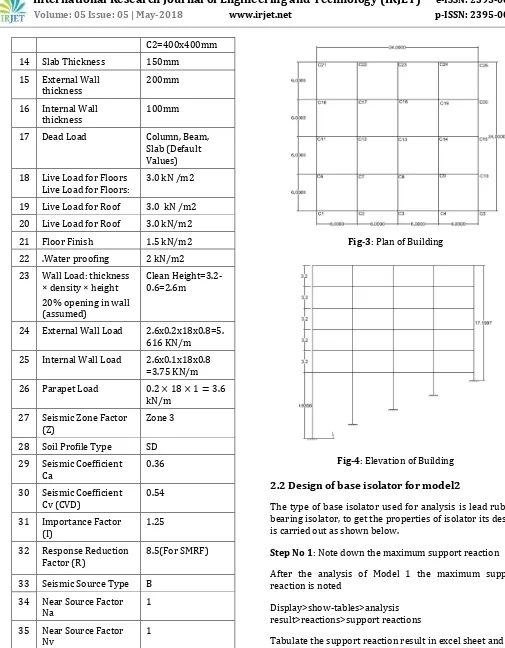
[image:2.595.319.550.497.780.2]© 2018, IRJET | Impact Factor value: 6.171 | ISO 9001:2008 Certified Journal | Page 3671 C2=400x400mm
14 Slab Thickness 150mm
15 External Wall
thickness 200mm
16 Internal Wall
thickness 100mm
17 Dead Load Column, Beam,
Slab (Default Values) 18 Live Load for Floors
Live Load for Floors: 3.0 kN /m2 19 Live Load for Roof 3.0 kN /m2 20 Live Load for Roof 3.0 kN/m2
21 Floor Finish 1.5 kN/m2
22 .Water proofing 2 kN/m2 23 Wall Load: thickness
× density × height 20% opening in wall (assumed)
Clean Height=3.2-0.6=2.6m
24 External Wall Load 2.6x0.2x18x0.8=5. 616 KN/m 25 Internal Wall Load 2.6x0.1x18x0.8
=3.75 KN/m 26 Parapet Load
kN/m 27 Seismic Zone Factor
(Z) Zone 3
28 Soil Profile Type SD 29 Seismic Coefficient
Ca 0.36
30 Seismic Coefficient
Cv (CVD) 0.54
31 Importance Factor
(I) 1.25
32 Response Reduction
Factor (R) 8.5(For SMRF)
33 Seismic Source Type B 34 Near Source Factor
Na 1
35 Near Source Factor
Nv 1
36 Damping coefficient
(BD or BM) 1
[image:3.595.38.543.44.692.2]37 Damping (βeff) 5%
[image:3.595.323.543.54.501.2]Fig-3: Plan of Building
Fig-4: Elevation of Building
2.2 Design of base isolator for model2
The type of base isolator used for analysis is lead rubber bearing isolator, to get the properties of isolator its design is carried out as shown below.
Step No 1: Note down the maximum support reaction
After the analysis of Model 1 the maximum support reaction is noted
Display>show-tables>analysis result>reactions>support reactions
Tabulate the support reaction result in excel sheet and get the maximum support reaction
Max support reaction (W)= 3066.05KN
Step No 2: Calculate Design Displacement (DD)
© 2018, IRJET | Impact Factor value: 6.171 | ISO 9001:2008 Certified Journal | Page 3672
Step No 3: Effective stiffness (Keff)
(
)
(
)
Step No 4: Energy dissipated per cycle (WD)
Step No 5: Force at design displacement or characteristic strength (Q)
Step No 6: Stiffness in rubber (K2)
Step No 7: Yield Displacement (DY)
We have
Step No 8: Recalculation of Q to QR
Step No 9: Calculation of area and diameter of lead plug Yield strength of lead is around 10Mpa the area of lead plug needed is
√
Step No 10: Revising Rubber stiffness Keff to Keff(R) (after revising Q to QR)
Step No 11: Total thickness of rubber layer (tr)
Where, γ = 100% (maximum shear strain of rubber)
Step No 12: Area of bearing
Step No 13: Diameter of bearing
√
Step No 14:.Shape factor
Where,
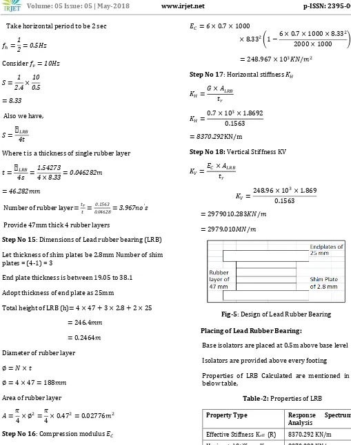
© 2018, IRJET | Impact Factor value: 6.171 | ISO 9001:2008 Certified Journal | Page 3673 Take horizontal period to be 2 sec
Consider
Also we have,
Where t is a thickness of single rubber layer
Number of rubber layer
Provide 47mm thick 4 rubber layers
Step No 15: Dimensions of Lead rubber bearing (LRB)
Let thickness of shim plates be 2.8mm Number of shim plates = (4-1) = 3
End plate thickness is between 19.05 to 38.1
Adopt thickness of end plate as 25mm
Total height of LRB (h)
Diameter of rubber layer
Area of rubber layer
Step No 16: Compression modulus
( )
Where, K- Bulk modulus = 2000 Mpa
G- Shear modulus = 0.7 Mpa
( )
Step No 17: Horizontal stiffness
KN/m
Step No 18: Vertical Stiffness KV
[image:5.595.33.542.50.694.2]
Fig-5: Design of Lead Rubber Bearing
Placing of Lead Rubber Bearing:
Base isolators are placed at 0.5m above base level
Isolators are provided above every footing
[image:5.595.309.542.63.536.2]Properties of LRB Calculated are mentioned in the below table,
Table-2: Properties of LRB
Property Type Response Spectrum
Analysis
Effective Stiffness Keff (R) 8370.292 KN/m
Horizontal Stiffness KH 8370.292 KN/m
Vertical Stiffness KV 2979.010 x103KN/m
Yield Strength QR 112.686 KN
Post Yield Stiffness Ratio 0.1
© 2018, IRJET | Impact Factor value: 6.171 | ISO 9001:2008 Certified Journal | Page 3674 2.3 Results and Discussion
2.3.1 Modal Analysis
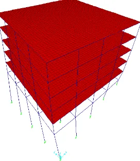
[image:6.595.344.505.95.242.2]We have shown three mode shapes of building and compared fixed base building with base isolated building.
Fig -6: Fixed Base Building for Mode1
[image:6.595.90.236.176.315.2]Fig -7: Base Isolated Building for Mode1
Fig -8: Fixed Base Building for Mode2
Fig -9: Base Isolated Building for Mode2
Fig -10: Fixed Base Building for Mode3
[image:6.595.364.521.310.457.2] [image:6.595.375.511.516.673.2]© 2018, IRJET | Impact Factor value: 6.171 | ISO 9001:2008 Certified Journal | Page 3675 2.3.2 Model time period
Chart -1: Model Time Period
The time period of two models are Shown in Chart-1, we can observe that model 2 which is base isolated by providing lead rubber bearing at base have increase in time period in all Twelve modes when compared to model 1 which is fixed base.
2.3.3 Equivalent Static Analysis
Chart -2: Displacement
From Chart-2 it is observed that, in case of RC building analyzed by the equivalent static method Storey displacement in the base isolated structures increased by some percentage as compared to fixed base structures. Similarly In Y direction also storey displacement in the base isolated structures increased by some Percentage as compared to fixed base structures
Chart -3: Storey Drift
From the Chart-3, it is observed that in case of RC building analyzed by equivalent static method in the base isolated structure the storey drift significantly reduces as compared to fixed base structure.
Chart -4: Base Shear
From the Chart-4, it is observed that in case of RC building analyzed by equivalent static method in the base isolated structure the Base Shear reduces by some percentage as compared to fixed base structure.
Column Forces
Exterior column
Chart -5: Max Axial force for column C1 at level 1
From the Chart-5, it is observed that in case of RC building analyzed by equivalent static method in the base isolated structure the Axial Forces of exterior Column significantly Increases as compared to fixed base structure.
© 2018, IRJET | Impact Factor value: 6.171 | ISO 9001:2008 Certified Journal | Page 3676 From the Chart-6, it is observed that in case of RC building
analyzed by equivalent static method in the base isolated structure the Shear forces developed at exterior Column its Slightly decreases as compared to fixed base structure
Chart -7: Max Bending moment for column C1 at level 1
From the Chart-7, it is observed that in case of RC building analyzed by equivalent static method in the base isolated structure the bending moment developed at exterior column its Significantly Reduces as compared to fixed base structure. The Bending moment developed at exterior column of Base isolated structure is negligible.
Chart -8: Max torsion for column C1 at level 1
From the Chart-8, it is observed that in case of RC building analyzed by equivalent static method in the base isolated structure the Torsion at exterior column is zero. But in Case of Fixed Base Building Torsion is less as compared to Base Isolated Building.
Internal Column
Chart -9: Max Axial force for column C13 at level 1
From the Chart-9, it is observed that in case of RC building analyzed by equivalent static method in the base isolated structure the Axial Forces of interior column increases more rapidly as compared to fixed base structure
Chart -10: Max Shear force for column C13 at level 1
From the Chart-10, it is observed that in case of RC building analyzed by equivalent static method in the base isolated structure the Shear Forces Developed at interior column its Slightly Increases as compared to fixed base structure
Chart -11: Max Bending moment for column C13 at level 1
From the Chart-11, it is observed that in case of RC building analyzed by equivalent static method in the base isolated structure the Bending Moment Developed at Interior Column its Significantly Reduces as compared to fixed base structure.
Chart -12: Max torsion for column C13 at level 1
© 2018, IRJET | Impact Factor value: 6.171 | ISO 9001:2008 Certified Journal | Page 3677 But in Case of Fixed Base Building Torsion is less as
compared to Base Isolated Building.
2.3.4 Response Spectrum Analysis
Chart -13: Displacement
From Chart-13, it is observed that, in case of RC building analyzed by the Response Spectrum method Storey displacement in the base isolated structures increased by some Percentage as compared to fixed base structures. Similarly In Y Direction also storey displacement in the base isolated structures increased by some Percentage as compared to fixed base structures
Chart -14: Storey Drift
From the Chart-14, it is observed that in case of RC building analyzed by Response Spectrum method in the base isolated structure the storey drift significantly reduces as compared to fixed base structure than that of same building analyzed in both X and Y directions
Chart -15: Base Shear
From the Chart-15, it is observed that in case of RC building analyzed by equivalent static method in the base
isolated structure the Base Shear reduces by some percentage as compared to fixed base structure.
Column Forces:
Exterior column
Chart -16: Max Axial force for column C1 at level 1
From the Chart-16, it is observed that in case of RC building analyzed by Response Spectrum method in the base isolated structure the Axial Forces of Exterior Column Decreases as compared to fixed base structure.
Chart -17: Max Shear force for column C1 at level 1
From the Chart-17, it is observed that in case of RC building analyzed by Response Spectrum method in the base isolated structure the Shear Forces Developed at Exterior Column its Slightly Increases as compared to fixed base structure.
© 2018, IRJET | Impact Factor value: 6.171 | ISO 9001:2008 Certified Journal | Page 3678 From the Chart-18, it is observed that in case of RC
building analyzed by Response Spectrum method in the base isolated structure the bending moment developed at exterior column its Significantly Increases as compared to fixed base structure
Chart -19: Max torsion for column C1 at level 1
From the Chart-19, it is observed that in case of RC building analyzed by Response Spectrum method in the base isolated structure the Torsion at exterior column is zero. But in Case of Fixed Base Building Torsion is more as compared to Base Isolated Building.
Interior column
Chart -20: Max Axial force for column C13 at level 1
From the Chart-20, it is observed that in case of RC building analyzed by Response Spectrum method in the base isolated structure the Axial Forces of Interior Column Increases more rapidly as compared to fixed base structure
Chart -21: Max Shear force for column C13 at level 1
From the Chart-21, it is observed that in case of RC building analyzed by Response Spectrum method in the base isolated structure the Shear Forces Developed at Interior Column its Slightly Increases as compared to fixed base structure
Chart -22: Max Bending Moment for column C13 at level
From the Chart-22, it is observed that in case of RC building analyzed by Response Spectrum method in the base isolated structure the Bending Moment Developed at Interior Column its more as compared to fixed base structure
Chart -23: Max torsion for column C13 at level 1
From the Chart-23, it is observed that in case of RC building analyzed by response spectrum method in the base isolated structure the Torsion at interior column is zero. But in Case of Fixed base Building torsion is more as compared to Base Isolated Building.
3. CONCLUSIONS
1. There is considered reduction in storey shear, base shear and storey drift was observed for base isolated building compared with the fixed base building of some properties.
© 2018, IRJET | Impact Factor value: 6.171 | ISO 9001:2008 Certified Journal | Page 3679 model shows considerable amount of lateral
displacement at base. Also it has been observed that as floor height increases, lateral displacement increases in fixed base building as compared to base isolated building. During earthquake due to this reduction in lateral displacement damages of structural as well as nonstructural is reduced.
3. Increase in roof displacement was observed for isolated building compared to fixed base building. The increase in roof displacement may be because of the initial displacement at base level which there in isolated building. In case of irregular building analyzed by the equivalent static method storey displacement in the base isolated structures increased by 34.20% as compared to fixed base structures. And by the response spectrum method storey displacement in the base isolated structures increased by 59.35% as compared to fixed base structures.
4. Mode periods are increased which increases reaction time of a structure during earthquake
5. Finally it is concluded that after LRB is provided as base isolation system it increases the structures stability against earthquake.
6. Compared to equivalent static method the analysis results obtained by response spectrum method are very significant.
7. As storey height increases, the storey drift in base isolated building decreases as compared to fixed base building which makes structure safe against earthquake.
REFERENCES
[1] Venkatesh,Mr.Arunkumar.H.R,(2015)”Low-Cost Base-Isolation System for Seismic Protection of Rural Buildings” ,10.1061/(ASCE)SC.1943-5576.0000254.
[2]ShameenaKhannavar,KolharM.H.,AnjumAlgur,(2017)“S eismic Analysis of RC Structures Using Base Isolation Technique”,ISSN: 2278-9359 (Volume-6, Issue-2).
[3] Sumana C.V., Raghu M.E., Er. Rajesh Harugoppa, (2016) “Comparative Study on Fixed base and Base Isolated Buildings on Sloping Ground”,Vol. 5, Issue 8, August 2016, ISSN (Print): 2347-6710.
[4]Linsu,GoodarzAhmadi,IradjTadjbakhshG.(1992),”Comp arative Study Of Base Isolation Systems”.
[5] Lin A. N.,ShentonH. W.,(1992)”Seismic Performance Of Fixed-Base Andbase-Isolated Steel Frames”.
[6] BarbatA. H., RodellarJ., RyanE. P., MolinaresN.,(1995),”Active Control Of Nonlinear Base-Isolated Buildings”, J. Eng. Mech. 1995.121:676-684.. [7]Prayag J. Sayani,Keri l. Ryan,(2009),”Comparative Evaluation of Base-Isolated and Fixed-Base Buildings Using a Comprehensive Response Index”, 10.1061/_ASCE_0733-9445_2009_135:6_698.
[8]SanthoshH.P., ManjunathK.S., K. Sathish Kumar, (2013),” Seismic Analysis of Low to Medium Rise Building for Base Isolation”,eISSN: 2319-1163 pISSN: 2321-7308.
[9] Dhananjay A. Chikhalekar,M. M.
Murudi,(2015),”Seismic Performance Of Structure With Fixed Base, Base Isolated Structure And Structure With Viscous Damper”,IJRET,eISSN: 2319-1163 | pISSN: 2321-7308.
[10] Manasa M S,Dr. Alice Mathai,(2017).” Performance of Lead Rubber Bearing as a Base Isolator”,IJSTE - International Journal of Science Technology &Engineering Volume 3 Issue 11 May 2017, ISSN (online): 2349-784X. [11] PrayagJ. Sayani, Keri L. Ryan, (2009),”Comparative Evaluation of Base-Isolated and Fixed-Base Buildings Using a Comprehensive Response Index”,journal of structural engineering © asce / june 2009, J. Struct. Eng. 2009.135:698-707.
[12] TianXueMin,Lu Ming,(2008),”Design of Base-Isolated Structure with Rubber-Bearing”.
[13]HashemiyekaniM.,MoghadamA.S.,ZiyaeifarM.,Hosseini M.(2008),”The New Method for Control and Reduction of Torsion with Base Isolation”.
[14] Radmila B. Salic, Mihail A. Garevski,Zoran V. Milutinovic (2008),” Response Of Lead-Rubber Bearing Isolated Structure”.
BIOGRAPHIES
Ishwari M. Amrutkar is student studying in department of civil engineering at R.H. Sapat college of engineering, Nashik, Maharashtra, India
© 2018, IRJET | Impact Factor value: 6.171 | ISO 9001:2008 Certified Journal | Page 3680 Vipula G. Badgujar is student
studying in department of civil engineering at R.H. Sapat college of engineering, Nashik, Maharashtra, India
Hardika G. Desale is student studying in department of civil engineering at R.H. Sapat college of engineering, Nashik, Maharashtra, India
Samreen A. Patel is student studying in department of civil engineering at R.H. Sapat college of engineering, Nashik, Maharashtra, India