© 2017, IRJET | Impact Factor value: 5.181 | ISO 9001:2008 Certified Journal
| Page 1531
Performance Study of Elevated Water Tanks under Seismic Forces
Furquan Elahi Shaikh
1, B K Raghuprasad
2, Amarnath K
31
M.Tech, Department of Civil Engineering, The Oxford College of Engineering & Technology, Bengaluru,
Karnataka, India
2,3
Professor, Department of Civil Engineering, The Oxford College of Engineering & Technology, Bengaluru,
Karnataka, India
---***---Abstract – Elevated water tanks are frequently used inseismic active regions and because of that the seismic behavior of them needs to be carefully analyzed and dealt with. Due to lack of understanding most of the elevated tanks were damaged in the past earthquakes and hence there is a need to properly understand the different factors governing the design. At present, IS 1893:1984 describes the seismic force criteria for elevated water tanks. The code does not take into account for the convective and impulsive pressure in the analysis of the tank and also assumes the tank to be a single degree of freedom system. The objective of this work is to assess the impact of earthquake forces on two types of tank systems based on their support mainly classified as Framed Staging and Shaft Staging. Response Spectrum Analysis is carried out and behavior of these staging systems is studied as per draft code Part II of IS 1893:2006 and IITk’s GSDMA guidelines. Parameters such as Base Shear, Nodal Displacement, Overturning Moment, and Vibration Analysis are obtained from an FEM software STAAD-Pro.
Key Words: Frame Type Staging, Shaft Type Staging, Single degree of freedom, Impulsive pressure, Convective pressure.
1. INTRODUCTION
The progress in the scientific research into the dynamic behavior of liquid storage tanks reflects the increasing significance of these structures. Early uses for liquid containers were found in the petroleum industry and in municipal water supply systems. As time progressed the use of these types of storage is not just limited to storage of flammable liquids or water but also extended to nuclear reactor installation and thus making the study of their vibration properties a matter of prime importance. Safety of elevated tanks is of significant importance as tanks carrying large volume of different types of liquids within them. Water tanks are circular, rectangular, square, conical or intze type. Based on their supporting system elevated tanks can be classified as framed staging and shaft staging tanks. Due to the importance of water in dire circumstances such as an earthquake this study is primarily focused on the seismic performance of an elevated water tank. The objective of this study is to analyze the two types of elevated water tanks namely
Frame type and Shaft type using FEM software STAAD-Pro and compare their results and establish which one is better performing under seismic loads. The seismic design criteria in India is given by IS 1893-2002 (Part I) which illustrates minimum loading standards and IS 4326-1993 which gives the design and detailing requirements for constructions of building structures.
2. LITERATURE REVIEW
© 2017, IRJET | Impact Factor value: 5.181 | ISO 9001:2008 Certified Journal
| Page 1532
circular walls of the tank.Their objective was to analyzethe tank at different staging height corresponding to different seismic zones of India. Dona Rose K J [6] studied the response of an elevated circular type water tanks to dynamic forces. Tanks of various capacities with different staging height are modeled using ANSYS software. The analysis is carried out for two cases namely, tank full and half level condition considering the sloshing effect along with hydrostatic effect. Time history analysis using draft code of IS 1893-2002 (part2) and the acceleration data from El Centro earthquake was taken. The peak displacements and base shear obtained from the analysis were also compared along with displacements. Jay Lakahnakiya [7] analyzed the hydrodynamic pressure of intze tank and comparison of the cost of water tank for different staging conditions like shaft and frame type. Staging part was analyzed in Staad Pro. V8i and the design was done in excel worksheet. After the complete design the quantity of material has been found and then costing of water tank is done using supply and sewage board. Mor Vytankatesh K. et al [8] studied the impact of seismic forces on RC shaft and framed type with different capacities which were placed in different seismic zones. Comparison of elevated tanks with different system capacities and seismic zones states that these parameters may considerably change the seismic behavior of tanks.
3. OBJECTIVE
To determine the hydrodynamic effects on elevated water tank, with different supporting systems i.e., framed staging and concrete shaft placed in different seismic zones, using the Housner’s model.
To determine maximum nodal displacement at the top.
Free vibration analysis for both frame type and shaft type staging in Zone II and Zone IV.
To determine overturning moment over the height for frame type and shaft type staging.
To determine base shear for frame type and shaft type staging.
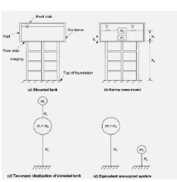
4. DESCRIPTION OF HOUSNER’S (1963) (1) MODEL
Elevated water tanks usually are never completely filled, due to which considering it as single degree of freedom system is not satisfactory. Therefore a partially filled tank cannot be idealized as a single degree of freedom system without taking into account the sloshing effect. The lateral stiffness for the frame type staging can be calculated by any FEM based software or manually, whereas the stiffness calculation for the shaft type staging is calculated by applying a horizontal force at the center of gravity of the tank and the unit nodal displacements are noted.
Fig 1 Two mass idealization as proposed by Housner
When the liquid mass in the tank is divided into two parts as shown in the above figure 1, the mass which vibrates along with the tank wall is called the impulsive mass. The mass which vibrates relative to the tank wall is called the convective mass. Housner (1963) [1] explained about the two mass model of elevated tank. In figure 1 we can see the masses “mc” and “mi” which represent the convective and impulsive masses respectively and “Kc” is corresponding stiffness. Figure 2 shows the pattern in which the impulsive and convective pressures are to be applied with “hi” and “hc” being the heights of the impulsive pressure (including base pressure) and convective pressure (including base pressure) respectively.
[image:2.595.308.559.84.342.2] [image:2.595.309.559.548.733.2]© 2017, IRJET | Impact Factor value: 5.181 | ISO 9001:2008 Certified Journal
| Page 1533
Parameters of elevated water tankSl. No Parameters Values
1 Diameter of the tank 10 m 2 Height of Cylindrical Wall 3 ml
3 Thickness of Cylindrical Wall 200 mm 4 Height of Staging 20 m 5 Number of Columns 8
6 Size of Column 600 x 600 mm 7 Size of Top Ring Beam 200 x 600 mm 8 Size of Bottom Ring Beam 200 x 600 mm 9 Size of Bracing 200 x 400 mm 10 Thickness of Top Dome 120 mm 11 Thickness of Bottom Dome 200 mm 12 Density of Concrete 25 kN/m3
13 Zone II & IV
14 Response Reduction Factor 2.5 15 Importance Factor 1.5
16 Type of Soil Hard (zone II ), Soft (Zone IV)
Table 1 Parameters of the Elevated Tank
Values of Partial Safety Factor γf for Loads (Clauses 18.2.3.1, 36.4.1 and B- 4.3) Load
Combination Limit State of Collapse Serviceability Limit State of
DL IL WL DL IL WL (1) (2) (3) (4) (5) (6) (7) DL + IL 1.5 1.0 1.0 1.0 - DL + WL 1.5 - 1.5 1.0 - 1.0
or 0.9(1)
DL + IL + WL 1.2 1.0 0.8 0.8
Table 2 Applied Load Combinations
NOTES
1. While considering earthquake effects substitute EL for WL.
2. For the limit state of serviceability, the values of γf given in this table for short term effects. While assessing the long term effects due to creep the dead load and hat part of the live load likely to be permanent may only be considered.
3. (1) This value is to be considered when stability against overturning or stress reversal is critical.
5. ELEVATED TANK WITH FRAME TYPE STAGING
Frame type stagings are used widely as compared to shaft type staging primarily because they are much better in performance. Earthquakes in the recent past have proved that the frame type staging performs much better than the shaft type staging. It primarily performs better because of the higher redundancy and due to the fact that it more ductile. The frame type staging consists of combination of beams and columns which makes it much more ductile and performs better in the event of an earthquake. The geometric properties of the tank primarily depend on the capacity and the height of the staging may vary from 10 to 20m. Generally for circular type of tank the diameter usually depends on the capacity.
Fig 3 Framed Type model prepared in Staad-Pro
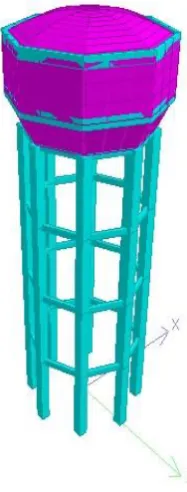
6. ELEVATED TANK WITH SHAFT TYPE STAGING
[image:3.595.386.480.293.540.2]© 2017, IRJET | Impact Factor value: 5.181 | ISO 9001:2008 Certified Journal
| Page 1534
Fig 4 Shaft Type model prepared in Staad-ProHowever for STAAD Pro analysis the pressures applied on the base of the wall of the tank and on the base slab are taken to be
i. ρ g hi*(impulsive mode) =
ii. ρ g hc*(convective mode) =
Where
ρ = Density of Water (kN/m3).
g = Acceleration due to gravity (m/sec2).
hi* = Height of Impulsive mass above the bottom of the tank (including base pressure).
hc*= Height of Convective mass above the bottom of the tank (including base pressure).
The shaft type staging can also be imagined as an inverted pendulum and hence it can be assumed that maximum resistance is going to be offered by the hollow shaft section. The load carrying capacity can be seriously hampered if there is any damage to the staging at the critical section. The dimensions of the tank primarily depend on the capacity and the height of the staging may vary from 10 to 20m. Generally for circular type of tank the diameter usually depends on the capacity it is supposed to carry but the thickness of the shaft usually varies between 120 mm to 200mm.
7. RESULTS AND DISCUSSION
1. Results for Convective Pressure
i. Time Period
Convective Mode
Mode Frame Type Shaft Type 1.00 2.09340 0.31858
[image:4.595.120.206.118.305.2]2.00 2.09340 0.31858 3.00 1.43227 0.12214 4.00 0.21799 0.07298 5.00 0.21788 0.07298 6.00 0.19351 0.06481
Table 3 Time Period for Frame & Shaft type Staging
Time periods in various modes for the frame type staging are much higher compared to those of shaft type staging.
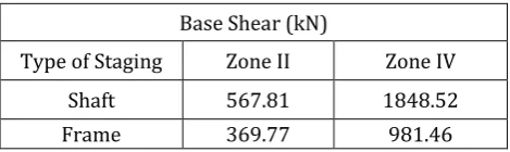
ii. Comparison of Base Shear
Base Shear (kN)
[image:4.595.331.566.265.335.2]Type of Staging Zone II Zone IV Shaft 567.81 1848.52 Frame 369.77 981.46
Table 4 Base Shear Results for frame & Shaft type Staging
Chart-1 Base Shears in Convective Mode
Figure 5 shows that the base shears for the frame type staging in Zone II and Zone IV are comparatively lower compared to those of shaft type staging.
iii. Nodal Displacements in Convective Mode
Nodal Displacements (mm)
Type of Staging Zone II Zone IV Shaft 3.509 11.331 Frame 70.069 231.98
Table 5 Nodal Displacements for frame & Shaft type Staging
0 500 1000 1500 2000
Zone II Zone IV
B
ASE
SH
E
AR
(k
N)
Base Shear
Shaft
[image:4.595.318.551.378.520.2]© 2017, IRJET | Impact Factor value: 5.181 | ISO 9001:2008 Certified Journal
| Page 1535
Chart-2 Nodal Displacements in Convective Mode From the above figure it is clear that the nodal displacements are higher for the frame type staging as compared to those of shaft type staging.
It also proves that the frame type staging is more flexible as compared to shaft type staging.
iv. Overturning Moments in Convective Mode
Overturning Moments (kN-m) Type of Staging Zone II Zone IV
[image:5.595.310.560.97.267.2]Shaft 323.61 1424.66 Frame 232.631 732.113
Table 6 Overturning Moment for Frame & Shaft type Staging
Chart-3 Overturning Moment
Since overturning moment is a governing factor in the design of an elevated water tank, it is observed that the overturning moment is higher for the shaft type staging as compared to frame type staging.
2. Result for Impulsive Pressure
i. Time Period
Impulsive Mode
[image:5.595.59.280.111.248.2]Mode Frame Type Shaft Type 1.00 2.214770 0.341130 2.00 2.214770 0.341130 3.00 1.521870 0.129660 4.00 0.218130 0.073630 5.00 0.218140 0.073630 6.00 0.193500 0.067270
Table 7 Time Period Results for Frame & Shaft type Staging
Time periods for the frame type staging are much higher as compared to those of shaft type staging.
Also as seen in the above table the time periods in impulsive mode values are much higher as compared to those in convective mode.
ii. Base Shear
Base Shear (kN)
Type of Staging Zone II Zone IV Shaft 710.46 2855.44 Frame 629.03 2507.02
Table 8 Base Shears for frame & Shaft type Staging
Chart-4 Base Shears in Impulsive Mode
Figure 8 shows that the Base shears for the frame type staging in Zone II and Zone IV are comparatively lower compared to those in shaft type staging.
It can also be seen that the base shear values of the impulsive mode are higher as compared convective mode.
0 50 100 150 200 250
Zone II Zone IV
No
da
l D
is
pla
ce
m
ent
(
m
m
)
Nodal Displacement
Shaft
Frame
0
500
1000
1500
Zone II
Zone IV
Over
turni
n
g M
om
en
t
(kNm
)
Overturning Moment
Shaft
Frame
0 500 1000 1500 2000 2500 3000
Zone II Zone IV
B
ASE
SH
E
AR
(k
N)
Base Shear
Shaft
[image:5.595.323.545.394.449.2] [image:5.595.321.550.494.640.2]© 2017, IRJET | Impact Factor value: 5.181 | ISO 9001:2008 Certified Journal
| Page 1536
iii. Nodal DisplacementsNodal Displacements (mm)
[image:6.595.320.552.108.255.2]Type of Staging Zone II Zone IV Shaft 38.66 154.22 Frame 148.53 600.707
Table 9 Nodal Displacements in Impulsive Mode
Chart-5 Nodal Displacements in Impulsive Mode
From the above figure it is clear that the nodal displacements are higher for the frame type staging compared to those in shaft type staging.
It may also be seen in the impulsive mode that the displacement values are much higher compared to those in convective mode.
iv. Overturning Moments
Table 10 Overturning Moments for Frame & Shaft type Staging
Overturning Moments (kN-m) Type of Staging Zone II Zone IV
Shaft 829.52 2420.14 Frame 466.026 1871.95
Chart-6 Overturning Moment
Since overturning moment is a governing factor in the design of an elevated water tank, it is observed that the overturning moment is higher for the shaft type staging as compared to that in frame type staging.
Also the overturning moment values in impulsive mode are much higher as compared to the convective mode.
8. CONCLUSIONS
Base shear is higher in the shaft type staging as compared to the frame type staging for convective and impulsive mode.
The increment in base shear is much higher as compared to hard soil to soft soil.
The nodal displacement values in shaft type are very low as compared to the frame type staging which suggests that the frame type staging is much more flexible and can return to its original position after a large deflection from its mean position.
The nodal displacement values are much higher in impulsive mode as compared to convective mode.
The shaft type staging has higher base shear values but lower nodal displacements values suggesting that the shaft type staging is brittle compared to frame type staging.
During designing an elevated water tank primary importance is given to the overturning moment, since large mass accumulates at the top of slender supporting system it is observed that the overturning moment for frame staging is less than that of tanks supported on shaft type staging.
Time period in convective and impulsive are similar for both frame type and shaft type staging.
Sloshing wave height is approximately same for the tanks, as it majorly depends on the capacity of the tank.
0 200 400 600 800
Zone II Zone IV
No
da
l D
is
pla
ce
m
ent
(m
m
)
Nodal Displacement
Shaft
Frame
0 500 1000 1500 2000 2500 3000
Zone II Zone IV
O
v
er
turnin
g
M
o
m
ent
(k
Nm
)
Overturning Moment
Shaft
[image:6.595.50.277.239.368.2]© 2017, IRJET | Impact Factor value: 5.181 | ISO 9001:2008 Certified Journal
| Page 1537
REFERENCES[1] Geroge W. Housner, “The Dynamic Behavior of Water
Tanks”, Bulletin of the Seismological Society of America.
[2] Jain Sudhir K , Sameer U , “Seismic Design of Frame
Staging for Elevated Water Tanks”
[3] Durgesh C. Rai, “Review of Code Design Forces For
Shaft Supports of Elevated Water Tanks”
[4] Pavan S Ekbote, Dr Jagadish G Kori, “Seismic Behavior
of RC Elevated Water Tank Under Different Types Of Staging Patterns”, Journal of Engineering, Computers & Applied Sciences
[5] Dona Rose K J, Sreekumar M, Anumod A S, “A Study of
Overhead Water Tanks Subjected to Dynamic Loads”, International Journal of Engineering Trends & Technology
[6] Jay Lakhanakiya, Prof. Hema J. Shah, “A Parametric
Study of an Intze Tank Supported on Different Stagings” International Journal for Scientific Research & Development
[7] Mor Vyankatesh K, More Varsha T, “Comparative
Study on Dynamic Analysis of Elevated Water Tank Frame Staging & Concrete Shaft Supported, IOSR Journal of Mechanical & Civil Engineering.
[8] Rupachandra J. Aware, Dr. Vageesha S. Mathada,
“Seismic Performance of Circular Elevated Water”, International Journal of Science and Research.
[9] IITK-GSDMA Guidelines for Seismic Design of Liquid