© 2017, IRJET | Impact Factor value: 5.181 | ISO 9001:2008 Certified Journal | Page 1977
COMPARISON STUDY OF OPTIMIZATION OF SURFACE ROUGHNESS
PARAMETERS IN TURNING EN1A STEEL ON A CNC LATHE WITH
COOLANT AND WITHOUT COOLANT
Girish Tilak
11
GirishTilak Assistant Professor, Department of Automobile Engineering, NewHorizon College of Engineering,
Karnataka, India
---***---Abstract -
This paper presents the comparison study optimization of surface roughness parameters in turning EN1A steel on a CNC lathe with coolant and without coolant. The optimization of machining processes is essential for the achievement of high responsiveness of production, which provides a preliminary basis for survival in today’s dynamic market conditions. The quantitative determination of Surface Roughness is of vital importance in the field of precision engineering. Machinability can be based on the measure of Surface Roughness. Surface Roughness depends on the factors such as Speed, Feed and Depth of Cut. In this work, the Taguchi methods, a powerful statistical tool to design of experiments for quality, is used to find the optimal cutting parameters for turning operations. Analysis of Variance has been used to determine the influencing parameters on the output responses. Using Taguchi technique, we have reduced number of experiments from 27 to 9 there by the total cost of the project is reduced by 66.66%. The results obtained are encouraging and the concluding remarks are helpful for the manufacturing industries.Key Words: surface roughness, Taguchi method, with coolant, parameters.
1.INTRODUCTION
The machinability of metal is defined as the ease with which a given material may be machined with a specific cutting tool. In other words the most machinable metal is one which will permit the fastest removal of the largest amount of material per cut of a tool with satisfactory finish. The operational characteristics of a cutting tool are generally described by its machinability which has 3 main aspects, tool life, surface finish and power required to cut. The quantitative determination of Surface Roughness is of vital importance in the field of precision engineering. Machinability can be based on the measure of Surface Roughness. Surface Roughness depends on the factors such as Speed, Feed and Depth of Cut. Other factors include cutting tool material, cutting tool geometry, machine condition, work piece material, cutting tool clamping and depend on operation carried out. The presence of coolant affects the Surface Roughness. Therefore an attempt has been made to conduct experimental investigation to optimize the Surface Roughness parameters in turning of EN1A steel on CNC lathe.
2.
EXPERIMENTATION
© 2017, IRJET | Impact Factor value: 5.181 | ISO 9001:2008 Certified Journal | Page 1978 L9 Orthogonal Array with Observations with Coolant.
Tria l No
Turning Parameter Output Responses
A Cuttin
g Speed (rpm)
B Feed (mm/ rev)
C Depth Of Cut (mm)
Surface Roughn ess,
Ra (µm)
Weight of specimen Before Turning
(gm)
Weight of specimen After Turning
(gm)
Machini ng Time (actual)
, t (sec)
Machining Time (theoretica
l), t (sec)
MRR(a) (mm3/min)
MRR(t) (mm3/min)
1 1000 0.1 0.2 3.19 197.301 182.706 70 58 2790.34 1200
2 1000 0.2 0.4 4.19 197.301 181.298 99 72 7474.44 7500
3 1000 0.3 0.6 4.29 197.301 178.660 94 70 14590.11 16800
4 2000 0.1 0.4 3.67 197.301 180.792 85 62 7890.48 7400
5 2000 0.2 0.6 3.79 197.301 178.520 19 26 18650 22600
6 2000 0.3 0.2 3.85 197.301 184.191 14 21 11930.35 11800
7 3000 0.1 0.6 2.84 197.301 177.867 19 28 14758.24 17200
8 3000 0.2 0.2 3.71 197.301 183.532 13 22 11776.78 12800
© 2017, IRJET | Impact Factor value: 5.181 | ISO 9001:2008 Certified Journal | Page 1979
3. RESULTS AND DISCUSSION
In this experiment turning operation was done on the work piece i.e., EN 1A Steel on a CNC lathe. Uncoated Carbide Insert was used for turning. 3 factors were selected i.e., Speed (rpm), Feed (mm/rev) and Depth of Cut (mm) at 3 levels and coolant was not used. Surface Roughness was measured using Profilometer (Talysurf) and the readings are tabulated in Table.
3.1 Analysis of Variance for Surface Roughness:
Source DF Seg SS Adj SS Adj MS F P RANK
Contribution Speed (rpm) 2 1.7727 1.7727 0.8864 1.85 0.351 2 19.64% Feed (mm/rev) 2 6.2228 6.2228 3.1114 6.50 0.133 1 69.00% Depth of Cut (mm) 2 1.0280 1.0280 0.5140 1.07 0.482 3 11.36% Error 2 0.9577 0.9577 0.4788
Total 8 9.9812 9.42 100%
Without coolant
Sou
rce DF Seg SS Adj SS Adj MS F P RANK Cont ribut ion Speed (m/
min) 2 2.412 2.412 1.2061 1.57 0.388 2 18.98% Feed (mm/
rev) 2 8.686 8.686 4.3430 5.67 0.150 1 68.56% Depth
of
Cut (mm) 2 1.573 1.573 0.7865 1.03 0.493 3
12.46%
Error 2 1.532 1.532 0.7662
Total 8 14.204 8.27 100%
With coolant
3.2 Response Table of Signal to Noise Ratios for Surface Roughness:
Levels Speed (rpm) (mm/rev) Feed Depth of Cut (mm)
1 -11.72 -10.15 -11.06
2 -11.53 -11.80 -11.79
3 -10.70 -12.00 -11.10
Delta 1.02 1.85 0.74
Rank 2 1 3
Without coolant.
Levels Speed (rpm) Feed (mm/rev) Depth of Cut (mm)
1 -10.769 -8.951 -10.012
2 -10.637 -10.972 -10.929
3 -9.611 -11.093 -10.075
Delta 1.158 2.142 0.917
Rank 2 1 3
© 2017, IRJET | Impact Factor value: 5.181 | ISO 9001:2008 Certified Journal | Page 1980
3.3 Graph showing the Main Effects Plot for S/N ratios of Ra(without coolant):
M e a n o f S N r a ti o s 3000 2000 1000 -10.0 -10.5 -11.0 -11.5 -12.0 0.3 0.2 0.1 0.6 0.4 0.2 -10.0 -10.5 -11.0 -11.5 -12.0
Speed (rpm) Feed (mm/rev)
DOC (mm)
Main Effects Plot (data means) for SN ratios
Signal-to-noise: Smaller is better
Figure 5: S/N ratio values for Surface Roughness
M e a n o f M e a n s 3000 2000 1000 4.0 3.8 3.6 3.4 3.2 0.3 0.2 0.1 0.6 0.4 0.2 4.0 3.8 3.6 3.4 3.2
Speed (rpm) Feed (mm/rev)
DOC (mm)
[image:4.595.192.406.124.264.2]Main Effects Plot (data means) for Means
Figure 6: Mean values for Surface Roughness
Highest S/N ratio gives optimum machining parameter. Hence from Figure 5 and Figure 6 it can be observed that optimum values of machining parameters to get minimum Surface Roughness are Speed (3000 rpm), Feed (0.1mm/rev) and Depth of Cut (0.2mm).
Confirmation Test: Turning was conducted at optimum cutting parameters i.e., Speed 3000 rpm, feed 0.1mm/rev and Depth of Cut 0.2mm and found that Surface Roughness as 1.94 µm.
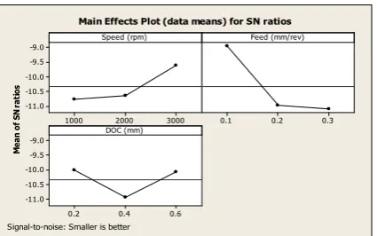
Graph Showing the Main Effects Plot for S/N Ratios of Ra(with coolant):
M ea n of S N ra ti os 3000 2000 1000 -9.0 -9.5 -10.0 -10.5 -11.0 0.3 0.2 0.1 0.6 0.4 0.2 -9.0 -9.5 -10.0 -10.5 -11.0
Speed (rpm) Feed (mm/rev)
DOC (mm)
Main Effects Plot (data means) for SN ratios
Signal-to-noise: Smaller is better
[image:4.595.194.403.303.460.2] [image:4.595.193.406.597.730.2]© 2017, IRJET | Impact Factor value: 5.181 | ISO 9001:2008 Certified Journal | Page 1981
M
ea
n
of
M
ea
ns
3000 2000 1000 3.6 3.4 3.2 3.0 2.8
0.3 0.2 0.1
0.6 0.4 0.2 3.6 3.4 3.2 3.0 2.8
Speed (rpm) Feed (mm/rev)
DOC (mm)
[image:5.595.184.412.96.235.2]Main Effects Plot (data means) for Means
Figure 6: Mean values for Surface Roughness
Highest S/N ratio gives optimum machining parameter. Hence from Figure 5 and Figure 6 it can be observed that optimum values of machining parameters to get minimum Surface Roughness are Speed (3000 rpm), Feed (0.1mm/rev) and Depth of Cut (0.2mm).
Confirmation Test: Turning was conducted at optimum cutting parameters i.e., Speed 3000 rpm, feed 0.1mm/rev and Depth of Cut 0.2mm and found that Surface Roughness as 1.37 µm.
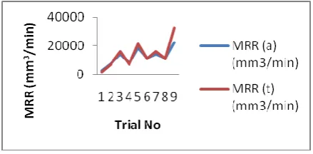
[image:5.595.188.408.375.483.2] [image:5.595.187.407.605.716.2]3.4 To Study the Comparison of Actual And Theoretical Values of MRR(without coolant):
Figure 7: shows the comparison of Actual and Theoretical values of MRR
From Figure 7 it can be seen that for all the trials of this experiment, Theoretical value of Material Removal Rate is more compared to Actual values of Material Removal Rate. Further it can be observed that Material Removal Rate is Maximum when the values of Speed, Feed and Depth of Cut are at maximum levels i.e., 3000 rpm, 0.3 mm/rev and 0.4 mm respectively. Also it can be observed that Material Removal Rate is Minimum when the values of Speed, Feed and Depth of Cut are at minimum levels i.e., 1000 rpm, 0.1 mm/rev and 0.2 mm respectively.
To Study the Comparison of Actual And Theoretical Values of MRR(with coolant):
Figure 7: shows the comparison of Actual and Theoretical values of MRR
© 2017, IRJET | Impact Factor value: 5.181 | ISO 9001:2008 Certified Journal | Page 1982
the values of Speed, Feed and Depth of Cut are at maximum levels i.e., 3000 rpm, 0.3 mm/rev and 0.4 mm respectively. Also it can be observed that Material Removal Rate is Minimum when the values of Speed, Feed and Depth of Cut are at minimum levels i.e., 1000 rpm, 0.1 mm/rev and 0.2 mm respectively.
4. CONCLUSION:
Following is the summary drawn based on the experiment conducted on EN 1A Steel alloy during turning operation with Uncoated Carbide Inserts without coolant.
1. Regression Model has been developed for Surface Roughness without coolant relating Speed, Feed and Depth of Cut to predict the value of the surface roughness.
2. The Analysis of Variance was performed to identify the influence of Machining Input parameters considered were Speed, Feed and Depth of Cut on the output Responses Surface Roughness using MINITAB software. Based on the Analysis of Variance the input parameters that are influencing the Output parameter Surface Roughness in their decreasing order are Feed, Speed and Depth of Cut.
3. Feed has the highest contribution of 69% followed by Speed 19.64% and Depth of Cut 11.36%.
4. The optimum values of machining parameters to get Optimum Surface Roughness are Speed of 3000 rpm, Feed of 0.1mm/rev and Depth of Cut of 0.2mm. Surface Roughness is found that is 1.94 µm. And average Surface Roughness is found to be 3.70 µm.
5. The Material Removal Rate is Maximum i.e., 22992.85 mm3/min when the values of Speed, Feed and Depth of Cut are
3000 rpm, 0.3 mm/rev and 0.4mm respectively. And Machining Time is 11 sec i.e., Minimum at this level.
6. The Material Removal Rate is Minimum i.e., 2790.34 mm3/min when the values of Speed, Feed and Depth of Cut are
1000 rpm, 0.1 mm/rev and 0.2 mm respectively. And Machining Time is 70 sec i.e., 1.5 times the Average at this level. 7. The average Material Removal Rate is 12540.06 mm3/min.
Following is the summary drawn based on the experiment conducted on EN 1A Steel alloy during Turning operation with Uncoated Carbide Inserts with Coolant.
1. Regression Model has been developed for Surface Roughness without coolant relating Speed, Feed and Depth of Cut to predict the value of the surface roughness.
2. The Analysis of Variance was performed to identify the influence of Machining Input parameters considered were Speed, Feed and Depth of Cut on the output Responses Surface Roughness using MINITAB software. Based on the Analysis of Variance the input parameters that are influencing the Output parameter Surface Roughness in their decreasing order are Feed, Speed and Depth of Cut.
3. Feed has the highest contribution of 68.54% followed by Speed 18.98% and Depth of Cut 12.46%.
4. The optimum values of machining parameters to get Optimum Surface Roughness are Speed of 3000 rpm, Feed of 0.1mm/rev and Depth of Cut of 0.2mm.Surface Roughness is found that is 1.37 µm. And average Surface Roughness is found to be 3.32 µm.
5. Improvement of Surface Roughness by 29.34% at the optimum values and by 10.27% at the average after using the coolant
6. The Material Removal Rate is Maximum i.e., 23214.28 mm3/min when the values of Speed, Feed and Depth of Cut are
3000 rpm, 0.3 mm/rev and 0.4mm respectively. And Machining Time is 11 sec i.e., Minimum at this level.
7. The Material Removal Rate is Minimum i.e., 2624.49 mm3/min when the values of Speed, Feed and Depth of Cut are
1000 rpm, 0.1 mm/rev and 0.2 mm respectively. And Machining Time is 49 sec i.e., Maximum at this level.
8. The average Material Removal Rate is 12729.57 mm3/min after using the coolant. Improvement of Material Removal
Rate by 1.48% at the average.
ACKNOWLEDGEMENT
© 2017, IRJET | Impact Factor value: 5.181 | ISO 9001:2008 Certified Journal | Page 1983
REFERENCES
[1].Gilbert W W (1950) “Economics of machining. In Machining” – Theory and practice. Am. Soc. Met.476–480
[2].ArmaregoEJ A, BrownRH (1969) “The machining of metals” (Englewood Cliffs, NJ: Prentice Hall) ASME 1952 Research committee on metal cutting data and bibliography. Manual on cutting of metals with single point tools 2nd edn.
[3].Brewer R C, Rueda R (1963) “A simplified approach to the optimum selection of machining parameters”.Eng. Dig. 24(9): 133–150
[4].Brewer R C (1966) “Parameter Selection Problem in Machining”. Ann. CIRP 14:11
[5].Bhattacharya A, Faria-Gonzalez R, Inyong H (1970) “Regression analysis for predicting surface finish and its application in the determination of optimum machining conditions”. Trans. Am. Soc. Mech. Eng. 92: 711
[6].Walvekar A G, Lambert B K (1970) “An application of geometric programming to machining variable selection”. Int. J. Prod. Res. 8: 3
[7].Sundaram R M (1978) “An application of goal programming technique in metal cutting”. Int. J. Prod.Res. 16: 375–382 [8].Ermer D S, Kromordihardjo S (1981) “Optimization of multi-pass turning with constraints”. J. Eng. Ind.103: 462–468 [9].Hinduja S, Petty D J, Tester M, Barrow G (1985) “Calculation of optimum cutting conditions for turning operations”. Proc. Inst. Mech. Eng. 199(B2): 81–92
[10].Tsai P (1986) “An optimization algorithm and economic analysis for a constrained machining model”. PhD thesis, West Virginia University
[11].Gopalakrishnan B, Khayyal F A (1991) “Machine parameter selection for turning with constraints: An analytical approach based on geometric programming”. Int. J. Prod. Res. 29: 1897–1908
[12].Agapiou J S (1992) “The optimization of machining operations based on a combined criterion, Part 1: The use of combined objectives in single-pass operations”, Part 2: Multi-pass operations. J. Eng. Ind., Trans. ASME 114: 500–513
[13].Prasad A V S R K, Rao P N, Rao U R K (1997) “Optimal selection of machining parameters for turning operations in a CAPP system”. Int. J. Prod. Res. 35: 1495–1522
[14].Zhou Q., Hong G. S. and Rahman M., (1995), “A New Tool Life Criterion For Tool Condition Monitoring Using a Neural Network”, Engineering Application Artificial Intelligence, Volume 8, Number 5, pp. 579-588.
[15].Lin W. S., Lee B. Y., Wu C. L., (2001), “Modeling the surface roughness and cutting force for turning”, Journal of Materials Processing Technology, Volume
108, pp. 286-293.
[16].Feng C. X. (Jack) and Wang X., (2002), “Development of Empirical Models for Surface Roughness Prediction in Finish Turning”, International Journal of Advanced Manufacturing Technology, Volume 20, pp. 348–356.
[17].Suresh P. V. S., Rao P. V. and Deshmukh S. G., (2002), “A genetic algorithmic approach for optimization of surface roughness prediction model”, International Journal of Machine Tools and Manufacture, Volume 42, pp. 675–680.
[18].Lee S. S. and Chen J. C., (2003), “Online surface roughness recognition system using artificial neural networks system in turning operations” International Journal of Advanced Manufacturing Technology, Volume 22, pp. 498–509.
[19].Choudhury S. K. and Bartarya G., (2003), “Role of temperature and surface finish in predicting tool wear using neural network and design of experiments”, International Journal of Machine Tools and Manufacture, Volume 43, pp. 747–753. [20].Chien W.-T. and Tsai C.-S., (2003), “The investigation on the prediction of tool wear and the determination of optimum cutting conditions in machining 17-4PH stainless steel”, Journal of Materials Processing Technology, Volume 140, pp.340–345. [21].Bhattacharyya, A., Reprinted 2006, “Metal Cutting: Theory and Practice”, New Central Book Agency, Page No. 495 – 501. ISBN: 81-7381-228-4.
[22].DIN 4760: Form deviations; concepts; classification system. Deutsches Institute FuerNormung, e.V., 1982.
[23].Groover, Mikell P. (2007). “Theory of Metal Machining”, Fundamentals of Modern Manufacturing, 3rd ed, John Wiley & Sons, Inc. ISBN 0471744859
[24].Kaczmarek J., 1983 “Principles of machining by cutting”, abrasion and erosion. London: Peter Peregrinus.
[25].Kalpakjian S. and Schmid Steven R. (2000), “Manufacturing Engineering and Technology”, 4th ed, Pearson Education Asia. ISBN 81-7808-157-1.
[26].Manly, B. F. J., (1994), “Multivariate Statistical Methods: A Primer”, Chapman and Hall, London.
© 2017, IRJET | Impact Factor value: 5.181 | ISO 9001:2008 Certified Journal | Page 1984