Universal Journal of Electrical and Electronic Engineering 6(4): 275-281, 2019 http://www.hrpub.org DOI: 10.13189/ujeee.2019.060409
Electric Vehicles Inductive Power Transfer System
Modeling, Simulation and Control
Nedaa N. Gaafar
1, Waheed Sabry
1,2,*1Valley Higher Institute for Engineering and Technology, Cairo, Egypt 2Department of Electrical Power and Energy, Military Technical College, Cairo, Egypt
Received August 7, 2019; Revised September 29, 2019; October 8, 2019 Accepted
Copyright©2019 by authors, all rights reserved. Authors agree that this article remains permanently open access under the terms of the Creative Commons Attribution License 4.0 International License
Abstract
Till the moment, electric vehicles charging statically using stationary stations, microgrids or other known conventional methods still represents a big problem for this industry, and a worrying snag to users. Due to different problems of electric vehicles charging using static methods, most of recent electric vehicles' researches are interested in the subject of charging these vehicles using inductive power transfer (IPT) or the so-called dynamic charging. This method depends mainly on transformer theory. In this paper, an IPT system is proposed, modeled in state-space form, simulated using MATLAB package and analyzed. The IPT system analysis focused on calculating one of the main system parameters - magnetic coupling coefficient and finding its optimal value. At this value, the transient dynamic voltage and current response of the circuit is found. Also, a fractional order proportional-integral-derivative (FO-PID) controller is proposed to enhance and smoothen the power signals (Voltage and current).Keywords
Inductive Power Transfer, Electric Vehicle, Electromagnetic Coupling, FO-PID1. Introduction
Because of the constant deficiency in providing non-renewable energy sources … coal, oil and gaseous petrol, and the constrained measures of hydro-electric age, the works in the non-ordinary power age and request increments from day to another; and because of a similar reason, the utilization of traditional autos that outfitted with warmth motors will slowly supplanted with crossover and electric vehicles.
From around 30 years back and therefore to inconsistency between regular fuel presence and developing of non-ordinary vitality sources, some new
wordings began to be brought up in the field of intensity building. Distinctive new terms will be thought about to ponder the normal future profile of electric power frameworks and related utility lattices: distributed generation (DG), smart grids, super grids, microgrids, digital power networks, active network management, transactive energy concept, internet of things -thinking- (IoT), and virtual power plants (VPPs) [1].
Traditional DGs are interconnected to the framework through distribution systems. However at this point, power is created by littler DG units at or close to client destinations can be associated with private systems out and out that segregated than huge framework. This aspect will lead the established DGs to another kind of systems; deregulated business condition or VPPs. This kind of plants will require active network management the executives through some new ideas like transactive energy idea. Likewise, smart grids, microgrids and digital power networks will play a role in this concept [2].
A microgrid is a discrete energy power system comprising of distributed energy sources and scattered demands. The fundamental reason for microgrids is to guarantee neighborhood, dependable, and moderate energy security for every single private network, while likewise giving answers for industrial and business customers. In spite of the fact that the principle goal of microgrids is self-supply and working freely on the distribution grid, might be there will be some monetary open doors for microgrids to be equipped for working in parallel with the fundamental power framework [3].
additionally coordinate with sustainable power sources, for example, sun powered, wind control, little hydro, geothermal, and squander to- energy.
Microgrids perform a dynamic power control over vitality sources, empowering self-ruling and programmed self-mending tasks. A microgrid can possibly be outfitted with energy adjusting facilities, for example, dispatchable demands like electric vehicles and substation storage units that could either add to minimization of power trade or augmentation of exchanging benefit.
Electric vehicles are cars that propelled with at least one electric motor drive. Electric vehicles are also interchange electric energy with energy storage units that built in the vehicle like batteries or supercapacitors. Due to shortage in conventional fuels supply, global warming and other environmental pollution conditions, electric cars are expected to dominate the automotive world in the future. Electric vehicles structure, development, performance and operation turned into a very outstanding issue.
The current issue in current versions of electric vehicles is the means by which to charge the vehicle. A lot of proposals are proposed to take care of this issue. In some cases the vehicle charging relies upon fixed stations like what occurs in ordinary autos. Some other time the vehicle charging relies upon recently arranged plugs on smart homes that exist in microgrids [4].
One of the suggested solutions for charging cars is the dynamic charging while the vehicle is moving instead of static (plug-in) charging. There are different methods were proposed for dynamic charging. The most famous methods are: wireless power transfer, capacitive wireless power transfer, conductive charging, inductive charging, inductive power transfer, resonant inductive power transfer, magnetic coupling, magnetic gear wireless power transfer, permanent magnet… etc.
Not all of these methods are easy to implement without any problem, but there are some problems facing each method. Of these problems, magnetic problems like skin effect, proximity effect, misalignment problems, high frequency leakage fluxes, air-gap problems … etc. Also, electric problems are existing like larger battery size, possible risks such as electric shock, trip hazards … etc. On general the cost and weight problems are exist in all cases [5].
One of the proposed solutions to solve the electric vehicle charging dilemma, is by using IPT systems. This solution method depends basically on the transformer theory with its electromagnetic coupling phenomenon. Really, this proposition faces different problems like vehicle dynamics, magnetic circuit problems … etc [6].
In this paper, an IPT system is proposed, modeled in state-space form; analyzed, solved and simulated using MATLAB package. The IPT system analysis focused on calculating magnetic coupling coefficient and studied its effects on main circuit parameters. Also, the results were optimized to get optimal value for system best performance
and optimal control design. A fractional order proportional-integral-derivative (FO-PID) controller is used to enhance and smoothen the power, voltage and current signals.
2. Modeling of IPT System under Study
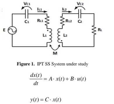
[image:2.595.331.527.228.406.2]System under study is shown in figure (1). The system is supposed as an IPT simple system with a series-series (SS) classical network. The system shown can be represented with state-space form, as [7-12]:
Figure 1. IPT SS System under study
) ( ) ( ) ( ) ( ) ( t x C t y t u B t x A dt t dx ⋅ = ⋅ + ⋅ = (1) where the state vector (x) and the input (u) are defined as:
T L C L
C I V I
V
x=( 1 1 2 2) ,u=E (2)
and the state matrices are defined as:
T L L L L L L k L L k k L B k L R R k L k L L kR k L L k C k L L R R k k L L k k L R k L C A − ⋅ − − = − + − − ⋅ − − ⋅ − − ⋅ + − − ⋅ − − − = ) 1 ( 0 ) 1 ( 1 0 ) 1 ( ) 1 ( 1 ) 1 ( ) 1 ( 1 0 0 0 ) 1 ( ) ( ) 1 ( ) 1 ( ) 1 ( 1 0 0 1 0 2 2 1 2 1 2 2 2 2 2 2 2 1 1 2 2 1 2 2 2 1 2 2 2 1 2 1 1 2 1 1 (3) If (k) is the magnetic coupling coefficient, the mutual inductance (M) is given by:
2 1 L
L k
M = ⋅ ⋅ (4)
where inductances L1 and L2 are defined as:
l AN L and l AN
Universal Journal of Electrical and Electronic Engineering 6(4): 275-281, 2019 277
1 2 2
1 /i or M N /i
N
M = φ = φ (6) Hence:
A N i l A N i l
k=φ /µ1 1 =φ /µ2 2 (7) and in both cases, (k) becomes proportional to (l / A), which means the parameter (l / A) will control the operation of this IPT system. The load power (PL) and power transfer
(transmission) efficiency (ηL) are given as:
} Re{ 2 1
2 1
* 1 2
2
L L L
L L L
I E P
R I P
⋅ ⋅ =
⋅ ⋅ =
η (8)
3. IPT System Simulation
The proposed IPT system model discussed in the previous section was simulated using MATLAB package.
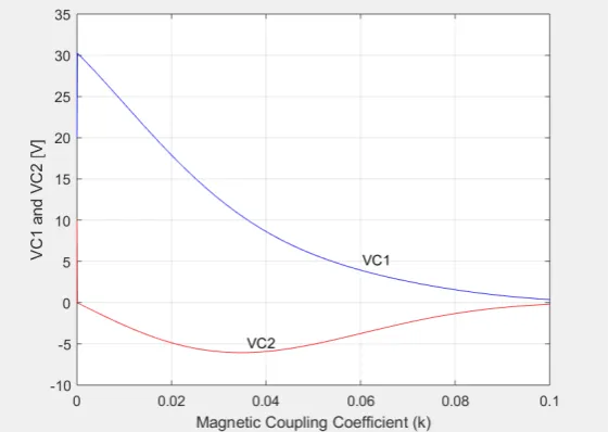
All system data is given in the appendix. The first simulation part is done to demonstrate the variation of both voltages VC1 and VC2 against the variations of magnetic
coupling coefficient (k). These variations are shown in figure (2). Variations of both currents IL1 and IL2 against the
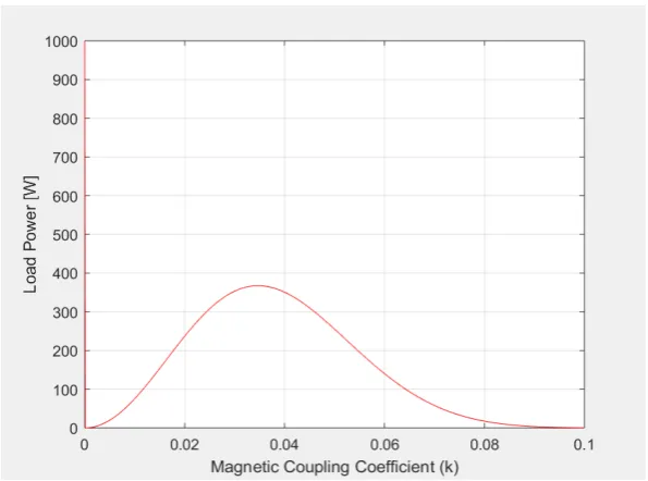
variations of magnetic coupling coefficient (k) are shown in figure (3). Also, the variations in load power (PL) and
power transfer efficiency (ηL) against (k) are shown in
figures (4) and (5). From figure (2), it's clear that from VC2
curve, that the optimum voltage occurs approximately at k
[image:3.595.158.439.332.531.2]= 0.035. In figure (4), it's clear that from load power curve, that the optimum load power occurs approximately at k = 0.035, also. In figure (5), it's clear that from power transfer efficiency curve, that the optimum value of power transfer efficiency occurs approximately at k = 0.05. From previous figures, the magnetic coupling coefficient (k) varies between 0.035 and 0.05 to get best performance of the IPT system. In the system dynamic response study (shown in next section), k will be considered as 0.04, as the mid-interval between 0.035 and 0.05.
[image:3.595.154.438.552.749.2]Figure 3. Currents vs magnetic coupling coefficient
Figure 4. Load power vs magnetic coupling coefficient
Figure 5. Power transfer efficiency vs magnetic coupling coefficient
4. FO-PID Controller
Intuitively, with FO controllers for integer order plants, there is a better flexibility in adjusting the gain and phase characteristics than using integer order controllers. This flexibility makes FO control a powerful tool in designing robust control systems with less controller parameters to tune. The key point is that using few tuning knobs, FO controller achieves similar robustness achievable by using very high-order integer order controllers [13-15].
Also, in case of using FO controllers to control integer order system, it's found that the transient and dynamic response becomes better than using integer order controllers. Since the trade off between the stability and
other control specifications always exists, introducing FO control makes it straighter forward to achieve a better trade off. Transfer function (T.F.) of FO-PID controller used is given as:
1 ) (
0 :
/ / . .
≤ ≤
⋅ + + = =
δ λ
δ λ
and where
S K S K K P I
P O F
T P I D
(9)
5. IPT System Dynamic Behavior
Universal Journal of Electrical and Electronic Engineering 6(4): 275-281, 2019 279
in two cases: the first case when the system operates freely without control and the second case when the system is equipped with a FO-PID controller.
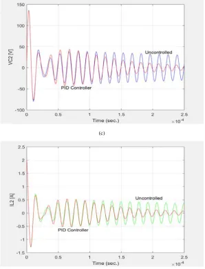
System observed signals are voltages (VC1 and VC2) and
currents (IL1 and IL2). In case of uncontrolled IPT system,
voltages are drawn with blue color and currents are drawn with green color as shown in figures (6-a, b, c and d). In case of controlled IPT system, voltages and currents are drawn with red color as shown in figures (6-a, b, c and d).
The FO-PID controller input signal (T.F. output) is considered to be capacitor voltage in secondary circuit
(VC2), and FO-PID controller output signal will be
negatively summed to IPT system input (E).
From figures (6-a, b, c and d), it can be recognize that the performance of IPT system when controlled is enhanced using FO-PID controller. Sure, the controller cannot satisfy all control design requirements, but it can satisfy most of which. In our IPT system case, signals oscillation amplitude in dynamic and steady-state interval are enhanced while during transient period, the controller is worst.
(a)
(c)
[image:6.595.149.448.81.472.2](d)
Figure 6. IPT system dynamic response
6. Conclusions
In the present paper, a dynamic system for charging electric vehicles using IPT system is proposed. This system depends mainly on transformer theory. The IPT system proposed is considered in its simplest structure (SS system). The system is modeled in state-space form, simulated using MATLAB package and analyzed. The IPT system analysis focused on calculating one of the main system parameters; magnetic coupling coefficient, and finding its optimal value. At this value, the transient dynamic voltage and current response of the circuit is found. Also, a fractional order proportional-integral-derivative (FO-PID) controller is proposed to enhance and smoothen the power signals (Voltage and current).
Appendix
IPT System Parameters [7]: C1 = C2 = 28.2 nF
L1 = 183.0 µH L2 = 193.0 µH RL = 20.0 Ω RL1 = RL2 = 0.1 Ω Power Components:
E = 250.0 V VC1 = 20.0 V VC2 = 10.0 V IL1 = 1.0 A IL2 = 2.0 A
FO-PID Controller Parameters: KP=4.5
Universal Journal of Electrical and Electronic Engineering 6(4): 275-281, 2019 281
REFERENCES
[1] W. Sabry, “From Distributed Generation to Virtual Power Plants: The Future of Electric Power Systems,” Proceedings of the 2018 20th International Middle East Power Systems Conference (MEPCON), Cairo, Egypt, pp. 162-166, December 18-20, 2018.
[2] N. Jenkins, J.B. Ekanayake and G. Strbac, “Distributed Generation,” The Institution of Engineering and Technology, 2010.
[3] Nikos Hatziargyriou, “Microgrid: Architectures and Control,” IEEE Press, 2013.
[4] K. T. Chau, “Electric Vehicle Machines and Drives: Design, Analysis and Application,” IEEE Press, 2015.
[5] Hany M. Mohamed, Mahmoud A. Abdalla, Abdelazez Mitkees and Waheed Sabry, “Overlapped Electromagnetic Coilgun for Low Speed Projectiles,” Journal of Magnetics, Automation and Electrical Systems, Vol. 20, No. 3, pp. 322-329, 2015.
[6] Chun T. Rim and Chris Mi, “Wireless Power Transfer for Electric Vehicles and Mobile Devices,” IEEE Press, 2017. [7] Emilio Tanowe Maddalena, Ruben Barros Godoy,
“State-Space Models for Assisting Loosely Coupled Inductive Power Transfer Systems Analysis,” Journal of Control, Automation and Electrical Systems, Vol. 2018, No. 29, pp. 119-124, 2018.
[8] R. W. Porto, S. Haffner, M. A. J. Coelho, V. J. Brusamarello, I. Müller and F. R. Sousa, “Variability Analysis of Efficiency and Output Power of an Inductive Power Transfer Link,” Journal of Control, Automation and Electrical Systems, Vol. 2018, No. 29, pp. 250-258, 2018. [9] Prasanth Venugopal, Soumya Bandyopadhyay, Pavol Bauer
and Jan Abraham Ferreira, “A Generic Matrix Method to Model the Magnetics of Multi-Coil Air-Cored Inductive Power Transfer Systems,” Energies, Vol. 10 (2017), No. 774, pp. 1-17, 2017.
[10]Masood Moghaddami, Aditya Sundararajan and Arif I. Sarwat, “A Power-Frequency Controller With Resonance Frequency Tracking Capability for Inductive Power Transfer Systems,” IEEE Transactions on Industry Applications, Vol. 54, No. 2, pp. 1773-1783, March/April 2018.
[11]Longbin Jiang, Liming Shi, Manyi Fan, Facong Zhang and Yaohua Li, “Segment Control Scheme of Inductive Power Transfer System for Rail Transit,” IEEE Transactions on Industry Applications, Vol. 54, No. 4, pp. 3271-3280, July/August 2018.
[12]Xiaofang Yuan, Yongzhong Xiang, Yan Wang, Xinggang Yan, “Neural Networks Based PID Control of Bidirectional Inductive Power Transfer System,” Neural Process Lett., Vol. 2016, No. 43, pp. 837-847, 2016.
[13]W. Sabry, and A. E. Eliwa, “New Design of a Fractional Order Controller Based on Padé Approximation to Enhance a Stable Power System Load Frequency,” International Review of Automatic Control (I.RE.A.CO.), vol. 11, No. 5, September 2018.
[14]Zakaria Ebrahim Khalil, Abd El-Fath El-Said Eliwa and
Waheed Sabry, “A Design of a Modified Power System Stabilizer for Power System Transient Stability Enhancement,” 2018 Twentieth International Middle East Power Systems Conference (MEPCON), Cairo University, Egypt, pp. 712-717, December 18-20, 2018.