Grid Tied Fuel Cell System Using Single Phase PLL Based
SOGI with PI and PR Current Controllers
M.Emin Meral
*, Doğan Çelik
Department of Electrical and Electronics Engineering Yuzuncu Yil University, Turkey
Copyright ©2016 by authors, all rights reserved. Authors agree that this article remains permanently open access under the terms of the Creative Commons Attribution License 4.0 International License.
Abstract
Renewable energy sources (RES) like the
solar and wind can't produce energy all the time due to depending air condition. But Fuel Cells (FCs) can be stored until it's needed. Power electronics plays an important role in converting the input power which is suitable delivered to the utility grid. Voltage source inverter (VSI) is the most widely used solution for connecting a low power RES tied the grid. This paper present grid tied fuel cell system using single phase phase-locked loop (PLL) based second order generalized integrator (SOGI) with proportionalintegral (PI) and proportional resonant (PR) current/power controllers. The SOGI algorithm is used with PLL in order to synchronize grid phase and amplitude. Solid oxide fuel cell (SOFC) which is one of FC types is analysed under constant and various DC load. Controllers of the PI and PR are discussed in order to obtain the control of inverter along with the variation of active power and grid voltage drop. The system is modelled and simulated using PSCAD/EMTDC software package. Simulation results show the effectiveness of both the controllers and PLL technique based SOGI for the synchronising of the SOFC systems with the single phase grid successfully.
Keywords
SOGI, Single Phase PLL, PR CurrentController, PI Current Controller, SOFC
1. Introduction
In the last years, an interest supporting Fuel Cell (FC) studies has grown, as FCs are a clean and efficient source of electricity, and have a wide range of transportation and stationary applications. FCs have a wide variety fields including, auxiliary power, transportaiton, stantionary power buildings and cogeneration applications. FCs are capable of operating at efficiencies greater than traditional energy production methods. Moreover, the scalability of FCs has allowed for applications in almost every field. FC systems can be easily placed at any side in a power system for grid system. Therefore, proposed controllers need to be designed
for a fuel cell system to make its performance characteristics as desired [1]. There are different types of fuel cells which are classified according to their electrolyte material and operating temperature such as Proton Exchange Membrane (PEMFC), Alkaline, Phosphoric Acid, Solid Oxide (SOFC), Molten Carbonate and Direct Methanol Fuel Cells [2]. SOFC receives for pay attentions because of its high efficiency, higher power density, operating at high temperature and almost zero impact to environment as a tool for conversing energy into electricity. However, its expensive fabrication cost significantly limits the development of SOFCs for practical applications.
Generally, a power electronic converter is required to transfer the electricity generated from these energy sources to the utility grid. A single-phase VSI is the most suitable solution for connecting a low power RES to the single phase grid. To regulate the power exchange with the grid, and at the same time, reduce harmonic components in the alternating current (AC) side current, various control strategies have been proposed, such as proportional integrator (PI) controller and proportional resonant (PR) controller [3]. The control system for the inverter consists of the synchronization controller which is a phase locked loop (PLL) that constantly tracks the phase of the grid voltage [4]. The PLL is used to detect the phase of the grid voltage and for that purpose an orthogonal voltage system needs to be generated. In single-phase systems there is less information than in three-phase systems regarding the grid condition, so more advanced methods should be considered in order to create an orthogonal voltage/current system [5].
A second-order generalized integrator (SOGI) is used for generation of an artificial orthogonal voltage as input to the PLL. Generally, SOGI algorithm is used with a PLL for grid phase and amplitude to synchronize inverter. It is easy to implement and it can filter the input signal without delay time due to its natural resonance at the fundamental frequency .The SOGI algorithm is one of the most important methods to provide an orthogonal signal system that it is insensitive to the input signal noise [6].
cannot be a satisfactory controller for an AC system because of the steady-state error and the poor disturbance rejection [7].
PR current controllers have many applications in power electronics applications of grid tied inverters. The reasons for using these controllers are provided zero steady state error at the resonant frequency and it has low order current harmonic content [8].
There are less information and studies on SOFC system synchronizing with the single phase grid than synchronizing with the three phase grid in the literature. This paper presents a single phase SOFC system (consist of FC, boost converter and inverter) using SOGI based PLL with PR and PI current controllers for the synchronizing with the single phase grid. The major contribution of this paper is comparison of total harmonic distortion (THD) and dynamic response speed of PR and PI current controllers. The system is modeled and simulated by using PSCAD/EMTDC software package.
2. Fuel Cell System Configuration
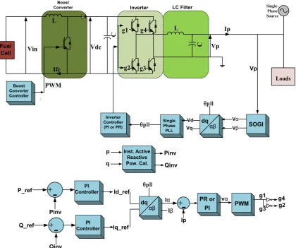
The implemented Fuel Cell system in PSCAD/EMTDC is shown in Fig. 1 where a single phase SOFC is connected to
DC/DC boost converter followed by an inverter, LC filter and single pahse grid. The inverter output voltage contains high order harmonics which must be eliminated and thus, a low LC filter and PR current controller are used to reduce the harmonic contents in the phase current and the output voltage. The technical details of each part of the FC system are given in the following subsections.
2.1. SOFC Design
The FC voltage and the reference power are determined the reference current which is determined for the FC current. The fuel flow is proportional with FC current. The dynamic model of the SOFC is presented based its electrochemical and thermodynamic characteristics [9, 10]. The partial pressure of hydrogen, oxygen and water are determined using the flow rates of hydrogen and oxygen. The FC current and pressure of gases affect the FC voltage [11]. A simulation model is developed for the SOFC in PSCAD/EMTDC based on the dynamic SOFC stack. The output voltage of FC is given by the Nernst equation. The ohmic loss of SOFC the results from the resistance of the electrodes and to the resistance of the flow of oxygen ions through the electrolyte.
L
C L
C
Loads
Vp
Ifc
Ip
Single-Phase Source
pll θ Boost
Converter Inverter LC Filter
Boost Converter Controller
Inverter Controller (PI or PR)
Single Phase
PLL SOGI
Vp
dθ
αβ VVβ
α Vd
Vθ
+
-+
-+
PI
Controller P_ref
Pinv Q_ref
Qinv
PR or PI Iα
Iβ Id_ref
Iθ_ref Ip
vα
PWM g1
g3 g2
g4
PI Controller
Inst. Active Reactive Pow. Cal.
Pinv Qinv p
θ
dθ αβ
g1 g4
g2 g3
Vdc
PWM Vin
Fuel Cell
pll θ
[image:2.595.96.517.382.733.2]pll θ
E0 is Standard reversible cell potential, rohmic is internal resistance of stack, Ifc is stack current, N is number of cells in stack, R is universal gas constant, T is stack temperature, F is Faraday’s constant, Valve molar constant for oxygen, hydrogen and water (KO2, KH2, KH2O), Kr (4N/F) constant, the fuel flow t reacts (
𝑞𝑞𝐻𝐻
2𝑟𝑟,
𝑞𝑞𝑂𝑂
2𝑟𝑟), the input fuel flow (𝑞𝑞𝐻𝐻
2,
𝑞𝑞𝑂𝑂
2), ratio of hydrogen to oxygen(
𝑟𝑟
𝐻𝐻𝐻𝐻)
and r flow of molar hydrogen and oxygen, considering ohmic losses of the SOFC stack, the expression of FC voltage can be written as𝑉𝑉𝑓𝑓𝑓𝑓=𝑁𝑁0�𝐸𝐸0+ 𝑅𝑅.𝑇𝑇
2𝐹𝐹�𝐼𝐼𝐼𝐼 𝑃𝑃𝐻𝐻2.𝑃𝑃𝑂𝑂20.5
𝑃𝑃𝐻𝐻2𝑂𝑂 �� − 𝑟𝑟𝑜𝑜ℎ𝑚𝑚𝑚𝑚𝑓𝑓.𝐼𝐼𝑓𝑓𝑓𝑓 (1)
PH2 is partial pressure of hydrogen;
𝑃𝑃𝐻𝐻2 =� 1 𝐾𝐾𝐻𝐻2
1+𝜏𝜏𝐻𝐻2.𝑆𝑆� �𝑞𝑞𝐻𝐻2−2𝐾𝐾𝑟𝑟.𝐼𝐼𝑓𝑓𝑓𝑓� (2) PO2is partial pressure of oxygen;
𝑃𝑃𝐻𝐻2 =� 1 𝐾𝐾𝑂𝑂2
1+𝜏𝜏𝑂𝑂2.𝑆𝑆�(𝑞𝑞𝑂𝑂2−2𝐾𝐾𝑟𝑟.𝐼𝐼𝑓𝑓𝑓𝑓) (3)
PH2O is partial pressure of water;
𝑃𝑃𝐻𝐻2𝐻𝐻=� 1 𝐾𝐾𝐻𝐻2𝑂𝑂
1+𝜏𝜏𝐻𝐻2𝑂𝑂.𝑆𝑆� �2𝐾𝐾𝑟𝑟.𝐼𝐼𝑓𝑓𝑓𝑓� (4)
Iref is the reference current ,
𝐼𝐼𝑟𝑟𝑟𝑟𝑓𝑓 =𝑃𝑃𝑉𝑉𝑟𝑟𝑟𝑟𝑟𝑟𝑟𝑟𝑓𝑓 (5)
𝐼𝐼𝑓𝑓𝑓𝑓=1+𝜏𝜏𝑟𝑟𝐼𝐼𝑟𝑟𝑟𝑟𝑟𝑟.𝑆𝑆 (6)
Molar flow rate of hydrogen and oxygen reacting;
𝑞𝑞𝐻𝐻2𝑟𝑟𝑟𝑟𝑓𝑓 = 2𝐾𝐾𝑟𝑟.𝐼𝐼𝑓𝑓𝑓𝑓 (7)
𝑞𝑞𝑂𝑂2𝑟𝑟𝑟𝑟𝑓𝑓 =𝑟𝑟𝐻𝐻𝑂𝑂𝑞𝑞𝐻𝐻2 (8)
The power output of fuel cell system is the product of stack current and voltage.
𝑃𝑃𝑓𝑓𝑓𝑓=𝑁𝑁0.𝑉𝑉𝑓𝑓𝑓𝑓.𝐼𝐼𝑓𝑓𝑓𝑓 (9)
2.2. Boost Converter Design
FC work at low DC voltages and so need to be step forward with the help of a converter [9]. Converter is used to increased and to regulate the DC voltage [12]. And also capacitor used for regulate the output voltage.The pulse width modulation(PWM) signal with PI Controller provides control and regulation of output dc voltage [13]. Converter is light weight efficient power conversion which are used in many application. Although different topologies converter, the basic converter used to step up input voltage is Boost converter [14].
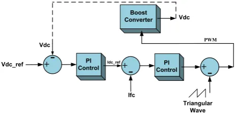
The switching signal to the IGBT is given by the closed loop feedback control system in Fig. 2. The error signal is fed into the compensator to obtain the control voltage. The
gate signal is produced by the PI controller. The converter’s output and the reference voltage are subtracted and the reference current (Idc_ref) is obtained. Then, Idc_ref and fuel cell current are subtracted and the error signal signal is fed into the comparator to compare with triangular wave to get the required PWM gate signal.
PI Control +
-PWM
+
-
+-PI
Control Boost Converter
Vdc_ref Vdc
Ifc
Vdc
[image:3.595.315.547.155.270.2]Triangular Wave Idc_ref
Figure 2. Boost Converter Feedback Controller System
2.3. Inverter Design
The model of the VSI used in this system based on the IGBT single-phase inverter model is developed. The inverter has two bridge arms, composed each one by two IGBT (with parallel) diodes as power switches [15].The SOFC-DC converter system is connected to grid through a DC-AC inverter. The transistor switching signals for the inverter are obtained from Current/Power control system.
The single-phase inverter is controlled by using a sinusoidal-pulse width modulation (SPWM) technique, its feedback is controlled by active and reactive power control with PR or PI current controllers.
3. Proposed Control Scheme
3.1. Single Phase (PLL) Based Second Order Generalized Integrator (SOGI)
In literature, Different methodologies [16] to form an orthogonal signal have been suggested for single phase PLLs and so, a second order generalized integrator (SOGI) is used in this paper. SOGI algorithm is used with PLL. The SOGI scheme is based on a frequency-adjustable resonator, which can be implemented by two cascaded integrators working in a closed loop in Fig. 3 [6].
The closed-loop transfer functions (Vα/Vp and Vβ/Vp)
are given as;
𝐻𝐻𝛼𝛼(𝑠𝑠) = 𝑠𝑠2+𝐾𝐾𝐾𝐾𝑠𝑠𝑠𝑠𝑠𝑠𝑠𝑠𝑠𝑠𝑠𝑠𝑠𝑠𝑠𝑠𝜔𝜔𝜔𝜔𝑠𝑠𝑠𝑠0𝑠𝑠+𝜔𝜔𝑠𝑠2 (10)
𝐻𝐻𝛽𝛽(𝑠𝑠) = 𝐾𝐾𝑠𝑠𝑠𝑠𝑠𝑠𝑠𝑠𝜔𝜔𝑠𝑠 2
𝑠𝑠2+𝐾𝐾𝑠𝑠𝑠𝑠𝑠𝑠𝑠𝑠𝜔𝜔𝑠𝑠𝑠𝑠+𝜔𝜔𝑠𝑠2 (11)
Where w0 is the nature frequency of signal and generates
Ksogi decreases, the filter becomes narrower resulting in a heavy filtering, but at the same time the dynamic response of the system becomes slower. The tuning of this structure is frequency dependent and can face problems when grid frequency has fluctuations. Therefore, the resonant frequency of SOGI is adjusted by the output frequency of PLL structure [17].
X
+- X
+
-β V
α
V
αβ
dq
α
V
β
V
Vd
+
-0 ref * Vd =
+
-pll θ
pll θ 0
w
Vp Ksogi ∫
∫
PI
Control ∫
0 w
[image:4.595.61.292.179.292.2]Vq
Figure 3. Single Phase PLL based SOGI Block Diagram
The control strategy can be applied in single-phase PLL by creating SOGI. Proposed a single phase PLL algorithm which is based on the inverse park transformation in equation 12 [17].
�𝑉𝑉𝑉𝑉𝑑𝑑
𝑞𝑞�=�
𝑐𝑐𝑐𝑐𝑠𝑠�𝜃𝜃𝑝𝑝𝑝𝑝𝑝𝑝� 𝑠𝑠𝑠𝑠𝐼𝐼�𝜃𝜃𝑝𝑝𝑝𝑝𝑝𝑝�
− 𝑠𝑠𝑠𝑠𝐼𝐼�𝜃𝜃𝑝𝑝𝑝𝑝𝑝𝑝� 𝑐𝑐𝑐𝑐𝑠𝑠�𝜃𝜃𝑝𝑝𝑝𝑝𝑝𝑝�� �
𝑉𝑉𝛼𝛼
𝑉𝑉𝛽𝛽� (12)
3.2. PI Current Controller
PI controller is one of the most widely use current tracking controller for grid tied inverter. The PI controller is expressed in eq. (13);
𝐺𝐺(𝑠𝑠) = 𝐾𝐾_𝑝𝑝+𝐾𝐾_𝑠𝑠/𝑠𝑠 (13) The value of the controller gains are not changing when the controller is transformed in difference reference frame, same value of Kp and Kican be used for the PI controllers.
3.3. The Proportional Resonant (PR) Current Controller In spite of its popularity, a PI controller is not able to track a sinusoidal reference without the steady-state error (magnitude and phase). PI controller such as lack of tracking a sinusoidal reference with zero steady-state error and poor disturbance rejection capability [18]. To overcome the mentioned problems of PI controller, PR current controller is proposed. The PR controller provides a high gain and zero steady-state error. Besides its simplicity, the system dynamics is almost not affected by the harmonic compensation terms. However, the PR controller is difficult to implement in reality. It has two problems. Firstly, the infinite gain introduced by a PR controller leads to an infinite quality factor which cannot be achieved in an analog or a digital system processor (DSP). Secondly, the gain of the PR controller is much decreased at other frequencies and it is not adequate to eliminate harmonic influence caused by grid voltage harmonics [19, 20].
A Fig. 4 show that 𝜔𝜔𝑜𝑜 is grid fundamental angular
frequency and ki is a constant which is carefully selected to shift the controller’s magnitude response vertically [18].
𝐺𝐺(𝑠𝑠) = 𝑘𝑘𝑝𝑝+𝑠𝑠2+2𝜔𝜔𝑘𝑘𝑠𝑠𝜔𝜔𝑓𝑓𝑠𝑠𝑓𝑓𝑠𝑠+𝜔𝜔𝑠𝑠2 (14)
And kp and kiare the proportional and integral gains of PR controller respectively, and 𝜔𝜔𝑓𝑓 is cut-off angular frequency.
The transfer function shows a no-ideal PR controller which has lower gain and wider bandwidth than ideal PR controller at the resonant frequency [18].
p k
c
w 2 +
-+
+
-B(s) A(s)
i
k
c
w 2
∫
2 o
[image:4.595.312.550.212.293.2]w ∫
Figure 4. PR Current Controller Block Diagram [22]
PR gain is finite, but it is relatively high for enforcing a small steady-state error. The controller’s bandwidth can be widened by setting ωc approprately, which helps to reduce sensitivity towards slight frequency variations [21].
4. Simulation Results
0 25 50 75 100 125 150
1.00 1.20 1.40 1.60 1.80 2.00 2.20 2.40
2.60 R
106.0 108.0 110.0 112.0 114.0 116.0 118.0 120.0 122.0 124.0 126.0 Vfc
0.0 2.0k 4.0k 6.0k 8.0k 10.0k 12.0k
14.0k Pfc
40 50 60 70 80 90 100 110 120 130 Ifc
t (s) t (s) t (s) t (s) a
b
c
d
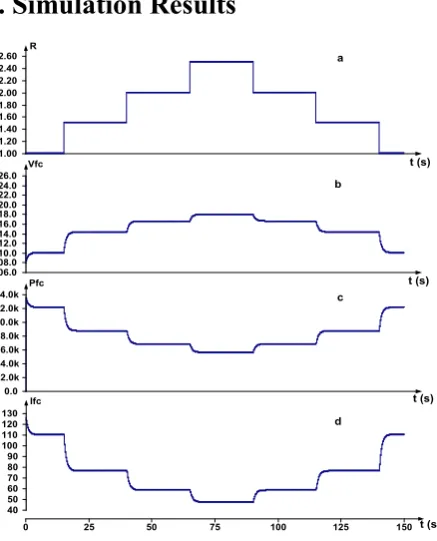
Figure 5. (a) Variable DC Load, (b) FC Voltage,(c) FC Power and (d)
FC Current
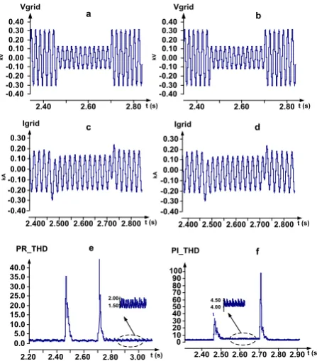
[image:4.595.320.539.392.663.2]controller due to a step change active power depending reference power in Fig.6. PR and PI controllers can control the system with the same dynamic performance when active power change depending reference power but PR has better performances in the grid voltage drop. When grid voltage decrease between 2.46s-2.7s, the response of PR controller is better than the PI controller. Fig.7 shows that THD is found to be 1.5% in case of PR controller and 4.5% in case of PI controller.
0.0 5.0 10.0 15.0
0.00 0.20 0.40 0.60 0.80 1.00
1.20 Pref P_PI P_PR
[image:5.595.65.277.195.309.2]t (s)
Figure 6. When power reference decrease and increase, active power with
PI and PR
PI_THD
2.40 2.60 2.80 -0.40
-0.30 -0.20 -0.10 0.00 0.10 0.20 0.30 0.40
Vgrid
2.40 2.50 2.60 2.70 2.80 2.90 0
10 20 30 40 50 60 70 80 90 100
2.400 2.500 2.600 2.700 2.800 -0.40
-0.30 -0.20 -0.10 0.00 0.10 0.20 0.30 Igrid
2.40 2.60 2.80 3.00 0.0
5.0 10.0 15.0 20.0 25.0 30.0 35.0 40.0
PR_THD
2.20
2.40 2.60 2.80 -0.40
-0.30 -0.20 -0.10 0.00 0.10 0.20 0.30 0.40
Vgrid
2.400 2.500 2.600 2.700 2.800 -0.40
-0.30 -0.20 -0.10 0.00 0.10 0.20 0.30 Igrid
t (s) t (s)
t (s) t (s) t (s)
kV
kA kA
kV
a b
c d
e f
t (s)
4.00 4.50 1.50
2.00
Figure 7. (a-b) Grid Voltage, (c-d) Grid Current with PI/PR, (e) PR-THD
and (f) PI-THD
5. Conclusions
The SOFC system, boost converter with a closed loop feedback control structure, grid tied single phase VSI and single phase PLL based SOGI with PI and PR control structure are modelled and simulated using PSCAD/EMTDC. Single phase system is needed to generate a pair of orthogonal voltages. Orthogonal signal is generated by SOGI. Single phase PLL technique based SOGI can be
used for the synchronising of the SOFC systems with the single phase grid. The performances of the PI and PR current controller are analysed. The advantage of PR controller reduces THD and achieves a high quality current.
REFERENCES
[1] Salam, A. A., Hannan, M. A., Mohamed, A. (2008). Dynamic Modeling and Simulation of Solid Oxide Fuel Cell System. 2nd IEEE International Conference on Power and Energy (PECon 08), 813-818. doi:10.1109/PECON.2008.47 62585
[2] Shouman, N., Hegazy, Y., Sakr, S. (2012). PSCAD Modeling and Analysis of PEM Fuel Cell Based Distributed Generators, Engineering and Technology (ICET), 1-6. doi:10.1109/ICEngTechnol.2012.6396165
[3] Monfared, M., Sanatkar, M., Golestan, S. (2012). Direct active and reactive power control of single-phase grid-tie converters, IET Power Electron, 5(8), 1544–1550. doi: 10.1049/iet-pel.2012.0131
[4] Assefa, H. Y., Danielsen, S., Molinas, M. (2009). Impact of PWM switching on modeling of low frequency power oscillation in electrical rail vehicle, Power Electronics and Applications, 1-9.
[5] Ciobotaru, M., Teodorescu, R., Blaabjerg, F. (2006). A New Single-Phase PLL Structure Based on Second Order Generalized Integrator, Power Electronics Specialists Conference, 1-6. doi:10.1109/PESC.2006.1711988
[6] Matas, J., Castilla, M., Vicuna, L. G., Miret, J., Vasquez, J. C. (2010). Virtual Impedance Loop for Droop-Controlled Single-Phase Parallel Inverters Using a Second-Order General-Integrator Scheme, IEEE Transactıons On Power Electronics, 25(12), 2993-3002. doi:10.1109/TPEL.2010.208 2003
[7] Vu, T.K, Seong, S.J. (2010). Comparison of PI and PR Controller Based Current Control Schemes for Single-Phase Grid-Connected PV Inverter, Korea Academic Industrial Society, 11 (8), 2968-2974.
[8] Ortiz Martinz, F., Mingorancia de Carvalho, K.C., Nasri Ama, N.R., Komatsu, W., Matakas, L. (2014). Optimized Tuning Method of Stationary FrameProportional Resonant Current Controllers, Power Electronics Conference (IPEC-Hiroshima 2014 - ECCE-ASIA), 2988-2995. doi:10.1109/IPEC.2014.68701
[9] Akkinapragada, N. (2007). Dynamıc Modelıng And Sımulatıons Of Solıd Oxıde Fuel Cells For Grıd-Tıed Applıcatıons (Master dissertation, Faculty Of The Graduate School Of The University Of Mıssourı-Rolla),. Retrieved from http://scholarsmine.mst.edu/.
[10]Fedakar, S. (2012). Experımental And Sımulatıon Studıes Of A Grıd Connected Solıd Oxıde Fuel Cell (Master dissertation, Institute of Sciences and Engineering). Retrieved from https://tez.yok.gov.tr/UlusalTezMerkezi/ [11]Fedakar, S., Bahceci, S., Yalcinoz, T. (2013). Modeling and
[image:5.595.65.289.343.598.2][12]Salam, A. A., Mohamed, A., Hannan, M. A. (2009). Improved Control Strategy for fuel cell and photovoltaic Inverter in a Microgrid, Wseas Transactions on Power Systems, 4(10), 331-340.
[13]Ngema, S. N., Saha, A. K., Ijumba, N. M. (2010). Power Converter for Proton Exchange Membrane Fuel Cell, Power System Technology (POWERCON), 1-6. doi:10.1109/POWERCON.2010.5666082
[14]Ciobotaru, M., Teodorescu, R., Blaabjerg, F. (2005). Control of single-stage single-phase PV inverter, Power Electronics and Applications, 1-10. doi:10.1109/EPE.2005.219501 [15]Garcia, C. A., Llorens, F., Garcia, P., Fernandez, L. M.,
Jurado, F. (2014). Improving voltage harmonic compensation of a single phase inverted-based PEM fuel cell for standalone applications, International Journal Of Hydrogen Energy, 39(9), 4483-4492
[16]Assefa, H. Y.(2009). Stability Investigation of an Advanced Electrical Rail Vehicle. (Master dissertation, Norwegian University of Science and Technology Department of Electric Power Engineering). Retrieved from http://www.diva-portal.org/
[17]Vishnu, M. (2013). DC Bus Current Ripple Management in Single Phase PWM Inverters, (Master dissertation, Department of Electrical Engineering Indian Institute of
Science). Retrieved from http://www.ee.iisc.ernet.in/ [18]Hojabri, M., Ahmad, A. Z., Toudeshki, A., Soheilirad, M.
(2012). An Overview on Current Control Techniques for Grid Connected Renewable Energy Systems, International Conference on Power and Energy Systems, 56(22), 119-126. doi: 10.7763/IPCSIT.2012.V56.22
[19]Sultani, J. F. (2013). Modellıng, Desıgn And Implementatıon Of D-Q Control In Single-Phase Grid-Connected Inverters For Photovoltaıc Systems Used In Domestic Dwellings. (Doctor Dissertation, Faculty of Technology De Montfort University). https://www.dora.dmu.ac.uk.
[20]Monfared, M., Golestan, S. (2012). Control strategies for single-phase grid integration of small-scale renewable energy sources, Renewable and Sustainable Energy Reviews, 16, 4982-499. doi:10.1016/j.rser.2012.04.017
[21]Komurcugil, H. (2014). Combined use Of Double-Band Hysteresis Current and Proportional Resonant Control Methods for Single-Phase UPS Inverters’, Industrial Electronics Society, 1305–1311. doi:10.1109/IECON.2014.7 048670