2016 International Conference on Electronic Information Technology and Intellectualization (ICEITI 2016) ISBN: 978-1-60595-364-9
The Study on Built-in Self-test Method Based
on FPGA
Ying Zhang, Jiasi Wang, Ting Sun and Liang Xiang
ABSTRACT
This paper proposed a built-in self-test method based on FPGA, which applied the traditional verification method of integrated circuit to FPGA test and proposed generating test vectors internally by using internal logic cells in FPGA. It also proposed judging the correctness of the test results by its own logic. This method has a lower dependence on external test facility, because the main test functions are all implemented on the FPGA. Meanwhile, it can give more assurance of testing by achieving a variety of fault excitation.
INTRODUCTION
In the field of traditional FPGA test, test excitation from the external parts of FPGA chips is normally adopted to drive the design under test (DUT) and to verify FPGA functions under physical or semi physical test environment. However, due to the limitation of the environment, a large amount of fault excitation fails to be implemented under the test environment, thus influencing the effect of FPGA test.[1]
Built-in self-test (BIST) is a fundamental method of design for testability (DFT) and was initially used in integrated circuit design. This paper proposed a built-in self-test method based on FPGA, which applied the traditional verification method of integrated circuit to FPGA test and proposed generating test vectors internally by using internal logic cells in FPGA. It also proposed judging the correctness of the
________________________
test results by its own logic[2]. This method has a lower dependence on external test facility, because the main test functions are all implemented on the FPGA. Meanwhile, it can give more assurance of testing by achieving a variety of fault excitation.
STRUCTURE OF BUILT-IN SELF-TEST(BIST)
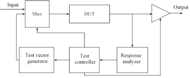
Basically, BIST is composed of four parts, namely test vector generator, DUT, output response analyzer (ORA) and test controller, which is used to manage the whole process. The structure of the system with BIST hardware is shown in Figure 1. BIST is able to conduct parallel tests on multiple design units, thus effectively reducing test duration. Under the test mode, the test vectors from the built-in test vector generator DUT are received as input. The frequently used test vector generator has linear feedback shift register (LFSR). The response from DUT is analyzed by using an additional response analyzer and the expected response of the test vector input is compared with the DUT response then. If there is any difference between the expected response and the DUT response, it indicates that an internal fault or faults have occurred to the DUT. The controller is applied to control application test vectors and observe the DUT response. The application of BIST test method requires no external ATE equipment. Self-test can be automatically completed, with low test costs[3].
[image:2.612.139.465.508.642.2]The test vector generator shown in Figure 1 mainly generates the input data necessary for DUT. It is used to automatically generate test excitation on DUT and load the excitation. Users may generate test vectors by using some algorithms, for example, by pseudo-random testing. Normally, there are three methods to test the vector generator. First, Exhaustive testing. Exhaustive testing is a test method in which all 2n test vectors are added to input ends when a combinational circuit with n inputs is tested.
Obviously, a binary counter may be used as the test vector generator. This method is able to test all testable faults having no time sequence in the circuit. Second, pseudo-exhaustive testing. Pseudo-exhaustive testing enjoys quite many advantages of exhaustive testing but requires less test vectors. Circuits are segmented in different forms and each segment is exhaustively tested. Practically, each segmented circuit is one of the subset of the original circuit and individual segments shall not intersect with one another. Circuits are segmented either logically or physically. And logical segmentation may be further divided into taper segmentation and sensitizing path segmentation. Third, pseudo-random testing. In circuit testing, test vectors are similar to random test vectors but are of certain cycles. Pseudo-random vectors may be generated in an alternative or non-alternative way. By alternative generation, it means a test vector can be generated several times in a cycle; and by non-alternative generation, it means none of the test vectors generated in a cycle is identical. No 2n pseudo random test vectors are required. An automatic LFSR may be employed to generate non-alternative test vectors. Pseudo-random testing is applicable to both combinational and time sequence circuits. Fault simulation and then test sequence of a proper length may be applied to achieve the expected fault coverage.
In this design, a linear feedback shift register (LFSR) is adopted to generate pseudo-random test vectors. As pseudo random codes are random numbers with desirable properties, they can repeat again and again, which is necessary for BIST. The test vectors generated by LFSR are able to obtain higher fault coverage within a short duration, thus improving testing efficiency.
The test controller mainly performs the functions of clock, resetting and controlled storage and transmission of data flow, controls DUT to read the excitation data generated by the test vector generator, delivers the data to DUT for algorithm verification, and then provides feedback of the relevant analyzer test results to the input ends for comparison and judgment.
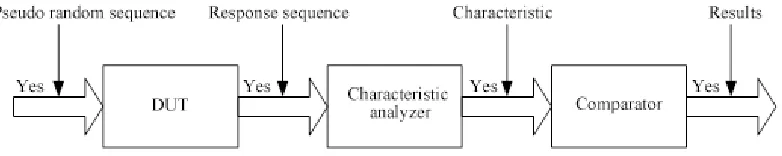
characteristic analyzer for characteristic extraction and comparison with the comparator. If the characteristic is the same with the correct one, DUT will be deemed normal; otherwise, DUT at fault, as shown in Figure 2 below.
If the polynomial expression of test response data flow M(t) is used as Dividend M(x), the polynomial expression p(x) of LFSR as divisor, and the polynomial expression Q(x) as quotient, the remainder R(x) or final status of LFSR will be obtained, which can be expressed as Eq. 1.
M(x)=p(x)·Q(x)+R(x) (1)
That is to say, when LFSR implements polynomial expression division operation on input sequence M(x) via characteristic polynomial expression p(x), the output sequence and the remainder R(x) corresponding to quotient Q(x) can be generated. The remainder (Rx) is correlated with the input sequence M(x).
SEMI PHYSICAL TEST PLATFORM
With FPGA as the core element, the Xilinx semi physical test platform is used to build a semi physical test environment featuring collaboration between hardware and software based on Xilinx FPGA realization. The test platform is mainly used to test the hardware and software collaboration system with the FPGA generation excitation module as the input of DUT. FPGA controls the sending, receiving and storage of data flow according to the specific interface sequence and acquires and analyzes the results generated by DUT.
The semi physical test platform can test/sample the test results in the built-in test module and finally transmit the acquired data or test results to FPGA for data analysis and comparison. “Built-in self-test” means that a test data generation, test result analysis or test control structure is built in the circuit so that the circuit can test the functions of some of its own modules.
[image:4.612.110.501.574.652.2]Verilog codes are written on the semi physical test platform so that the test vector generator generates and sends excitation data to DUT. The test controller controls the DUT to implement the functions of functional modules via the excitation data input, and sends the results to the response analyzer for analysis.
Through comparison against anomalies of input excitation, the platform can finish the fault response and analysis of abnormal data and images; greatly improve the fault coverage of DUT and solve the issue of failure in application of abnormal fault excitation.
Applied to FPGA test, the built-in self-test method can effectively utilize the resources on the board, conducts dynamic test towards FPGA modules without transforming the external circuits of chips, and test the correctness of the functions of internal system modules. It can supplement technical methods of dynamic test, conquer to some extent the difficulties in failed input of test excitation and insufficient test due to the limitation of the environment and improve the validity and effectiveness of dynamic test on software and hardware collaboration system.
CONCLUSION
In the built-in self-test method mentioned above, the test vector generator, test controller and response analyzer are designed on FPGA. The test vector generator generates excitation as input of DUT. The test controller is used to control the generation of sequence and the sending, receiving and storage of data flow. The response analyzer analyzes the results generated by the DUT and gives feedback to the input end. In this method, verification is carried out on the Xilinx semi physical test platform and the test excitation signals generated in FPGA are sent to the BIST system to drive the DUT. Through analysis of the results acquired in the built-in self-test, the correctness of FPGA functions can be verified fast, thus improving testing efficiency and sufficiency.
REFERENCES
1. Liu Baoyang. BIST Based FPGA Test with Delay Fault. Master Degree Thesis of Harbin Institute of Technology, pp. 7-8, 24-27, 2006.03.
2. Du Ying, Zhao Wenyan, An Baiyue, Design for Board-level BIST and its Realization Strategy Based on FPGA. Computer Measurement & Control, 16(3). pp. 389-391, (in Chinese), 2008.