Systems Reference Library
1iIIt
Tape Input-Output Instructions
This publication contains a description of the instruc-tions used by the data processing system to operate the tape units attached to it.
The instructions for the following tape units are in-cluded in this publication:
IBM 729 Magnetic Tape Unit IBM 7330 Magnetic Tape Unit IBM 7340 Hypertape Drive, Model 2 IBM 1011 Paper Tape Reader IBM 1012 Tape Punch
IBM 7335 Magnetic Tape Unit
Timing information is also included on the 729, 7330, and 7335 tape units.
File Number CenI-Ol Form A24-3069-l
MAJOR REVISION (OCTOBER, 1963)
This publication, Fonn A24-3069-1, replaces Fonn A24-3069-0, and the following Technical Newsletter: N24-0137.
Refer to IBM 1401/1460 Bibliography, Fonn A24-1495, or IBM
1440 Bibliography, Fonn A24-3005, for other publications.
© 1960, 1961, 1962, and 1963 by International Business Machines Corporation
Copies of this and other IBM publications can be obtained through IBM Branch Offices.
Address comments regarding the content of this publication to IBM Product Publications, Endicott, New York
Magnetic-Tape Operations.
Tape Units Data Flow
Magnetic-Tape Instructions. Read Tape.
Read Tape with Word Marks .. Write Tape.
Write Tape with Word Marks Backspace Tape Record Skip and Blank Tape Write Tape Mark. Diagnostic Read Rewind Tape
Rewind Tape and Unload. Branch if End of Reel Branch if Tape Error.
Magnetic-Tape Operating Considerations
IBM 729 Magnetic Tape Unit.
IBM 7330 Magnetic Tape Unit Magnetic -Tape Timing
IBM 729 II Tape Timings.
IBM 729 IV Tape Timings
IBM 729 V Tape Timings
IBM 729 VI Tape Timings IBM 7330 Tape Timings
IBM 1340 Hypertape Drive
Instructions Start Control. Start Sense . Start Read Start Write
Branch if Indicator On Response
IBM 1011 Paper Tape Reader
Instructions
Read from Paper Tape.
Read from Paper Tape with Word Marks .. Branch if Input/Output Indicator On Branch if Paper Tape Reader Ready
5 5 5 5 5 6 6 7 7 8 8 9 9 9 10 10 II II II II 12 13 14 15 15 18 18 18 18 20 22 22 22 24 24 24 24 25 25 Contents
IBM 1012 Tape Punch
Instructions
Write on Tape Punch Tape Punch Read Back Check Backspace Tape
Backspace Tape and Branch Branch if in Backspace Operation Branch if Tape Punch Ready
Branch if Tape Punch Not Ready to Accept Data Branch if Tape Punch is Not Ready to Read Branch if Tape Punch Overextended Branch if Supply Reel Low or Chad Box Full
IBM 1012 Programming Concepts
1. Move Character from Record into Test Location. 2. Decode to a Table Address
3. Get Table Argument for Punching 4. Punch Character in Tape. 5. Read-Check
6. End-of-Record Routine. 7. Automatic Error Correction. 8. End-of-Reel Routine. 9. Five-Track Tape Operation.
IBM 1335 Magnetic Tape Unit, Models 1 and 2
Data Flow.
Magnetic-Tape Instructions. Read Tape.
Read Tape with Word Marks Write Tape.
Write Tape with Word Marks Backspace Tape Record. Skip and Blank Tape Write Tape Mark Diagnostic Read. Rewind Tape.
Rewind Tape and Unload. Branch if End of Reel. Branch if Tape Error Read Binary Tape. Write Binary Tape. Magnetic-Tape Timing.
Read Operation"Timing Write Operation Timing
Index of Instructions
Magnetic-Tape Operations
Tape Units
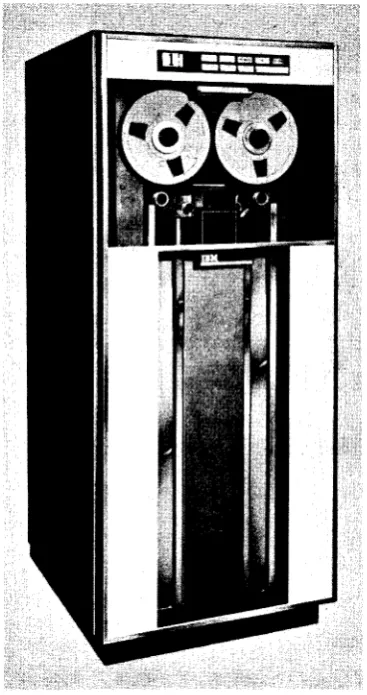
IBM 729 MAGNETIC TAPE UNIT (Figure 1)
[image:5.607.59.243.358.706.2]The 1401 system can use either of four models of the IBM 729 Magnetic Tape Units (Model II, Model IV, Model V, and Model VI). (The Model VI operates at Model IV speeds only.) The 1460 system can use 729 II, 729 IV, 729 V, or 729 VI magnetic-tape units. Either tape-oriented system can accommodate as many as six IBM 729 Tape Units which are attached to the tape adapter on the 1401 (attached to the 1461 on the 1460). The IBM 729 dual density tape unit makes it possible for the IBM 729 tape unit to operate with magnetic tapes recorded at either 200, 556, or 800 characters per inch.
Figure 1. IBM 729 Magnetic Tape Unit
Tape Input-Output Instructions
IBM 7330 MAGNETIC TAPE UNIT (Figure 2)
The 1401 and 1460 systems can also use the 7330 tape units as an input-output medium. The primary differ-ence between the 7330 and the 729 tape units is the processing speed.
Data Flow
IBM magnetic-tape units function in the systems as both input and output devices. They transport the magnetic tape and accomplish the actual reading and writing of information, as directed by outside control from the stored program.
Figure 2. IBM 7330 Magnetic Tape Unit
Magnetic-Tape Instructions
Read Tape
Instruction Format.
Mnemonic
SPS MU
A RT
0" Code A-address B-address d-character
M %Ux xxx R
begins to read magnetic tape, and continues to read until either an inter-record gap in the tape record or a group-mark with a word-mark in core storage is
sensed. The inter-record gap indicates the end of the tape record, and a group-mark (code CBA 8421) is inserted in core storage at this point.
If the group-mark with a word-mark occurs before the inter-record gap is sensed, the transfer of data from tape stops, but tape movement continues until the inter-record gap is sensed.
Word Marks. Word marks are not affected.
Timing. T
=
N (LI+
1) ms+
TJ,f. Time varies for type of tape unit and tape density used (see Timingsection). N = .0115 (1401), .006 (1460) Address Registers After Operation.
I-Add. Reg.
NSI
A-Add. Reg.
%4x
B-Add.Reg.
Group-mark
+
1Example. Read the record from tape unit 2 (labeled 2) into core storage. The high-order tape-record char-acter is moved to INPUT (0419), the next charchar-acter is moved to the next higher position (0420), etc., until transfer of data is stopped by an inter-record gap in the tape record, or a group-mark with a word-mark in core storage (Figure 3).
Autocoder
OPERAND
~.
~
Assembled Instruction:!! %U2 419 R Figure 3. Read Tape (Move Operation)
Read Tape with Word Marks
Instruction Format.
Mnemonic
SPS LU A RTW
Op Code A-address B-address d-character
b %Ux xxx R
Function. This is the same as the read tape operation, except that word-separator characters on magnetic tape (written during WRITE TAPE WITH WORD MARKS instruction) are translated to word marks during transmission into core storage.
Word Marks. A word-separator character read from tape causes a word mark to be associated with the next tape character transferred into core storage (Figure 4).
Tope Positions A B C 0
Tape Code 82 A841 41 C4
1401 Core Storage
Locations A B C
1401 Meaning 0 5 4
1401 Core Storage
Code C82 41W 4
Figure 4. Word-Separator Character Handling During Read Tape with Word Marks Operation
Timing. T
=
N (LI+
1) ms+
TH •Note. If a record has been written on tape by a WRITE TAPE WITH WORD MARICS instruction, it should be read back by a READ TAPE WITH WORD MARICS instruction so that word separa-tor characters will be translated to word marks.
Address Registers After Operation.
I-Add. Reg.
NSI
A-Add. Reg.
%4x
B-Add. Reg.
Group-mark
+
1Example. Read the record from tape unit 5 (labeled 5) into core storage, and insert word marks where word-separator characters exist in the tape record. The high-order character is moved to INREC1 (0518); the next character is moved to the' next higher position (0519), etc., until the transfer of data is stopped
by
an inter-record gap in the tape record, or until a group-mark with a word-mark is sensed in core storage (Figure 5).Autocoder
OPERAND
.. I
,::
'~.
,~
Assembled Instruction:! %U5 518 R Figure 5. Read Tape with Word Marks (Load Operation)
Write Tape
Instruction Format.
Mnemonic SPS MU
A WT
Op Code
M
A-addreu B-addreu d-character
•
Function. The tape unit designated in the A-address is started. The d-character specifies a tape write opera-tion. The data from core storage is written on the tape record. The B-address specifies the high-order position of the record in storage. A group-mark with a word-mark in core storage stops the operation. The group-mark with a word-mark causes an inter-record gap on the tape.
Word Marks. Word marks are not affected.
Timing. T
=
N (LI+
1) ms+
Til.Note. If a group-mark with a word-mark is the first character of B-address, the tape-adapter unit and the tape unit will hang up. The condition can be reset by pressing the start-reset key if the tape-select switch on the system console is in the N ( normal) position.
Address Registers After Operation.
I-Add. Reg.
NSI
A-Add. Reg.
%4x
B-Add. Reg. Group-mark
+
1Example. Transfer the contents of core storage to tape
unit 3 (labeled 3), starting at the location labeled OUTPUT (0525) and ending at the location of the first group-mark with a word-mark (Figure 6).
Autocoder
to
lobel 0:
Assembled Instruction: M Figure 6. Write Tape (Move Operation)
Write Tape with Word Marks
Imtruction Format.
%U3 525 W
Mnemonic SPS LU A W1W
Op Code A-address B-address d-character
b
%Ux xxx WFunction. This is the same as the write tape operation except that the WRITE TAPE WlTII WORD MARKS in-struction affects word marks in core storage.
Word Marks. A word mark associated with any
posi-tion in core storage causes a word-separator charac-ter (A84I) to be written automatically on tape, one character ahead of that which contained the word mark. Thus, word marks are translated to word-separator characters for tape storage (Figure 1).
1401 Core Storoge
Locotions A B C
1401 Core Storoge
Code C82 41W 4
1401 Meoning 0 5 4
Tope Positions A B C 0
Tope Code 82 A841 41 C4
Figure 7. Word-Separator Character Handling During Write Tape with Word Marks Operation
Timing. T
=
N (LI+
1) ms+
Til.Note. Load operations must be used when word marks are needed for identification in tape storage. If tape is written by a WRITE TAPE WITH WORD MARKS instruction, it must be read back by a READ TAPE WITH WORD MARKS instruction to insure proper translation between the tape and core storage.
Address Registers After Operation.
I-Add. Reg.
NSI
A-Add. Reg.
%4x
B-Add. Reg. Group-mark
+
1Example. Transfer the contents of core storage to tape
unit 6 (labeled 6). Insert a word-separator character where word marks exist in core storage, beginning at OUTREC (0696) and ending at the first group-mark with a word-mark in core storage (Figure 8).
Autocoder
lobel
0:
Assembled Instruction:! %U6 696 W Figure 8. Write Tape with Word Marks
Backspace Tape Record
Instruction Format.
Mnemonic SPS CU A BSP
OpCode
U
A-address %Ux
d-character B
Function. The tape unit specified in the A-address backspaces over one tape record. The first inter-record gap (IRG) encountered stops the backspace operation specified by the d-charaeter, B.
Word Marks. Word marks are not affected.
Timing. T = N (LI
+
1) ms+
Til.Note. Processing unit not interlocked during tape-movement
time.
Address Registers After Operation.
I-Add. Reg. NSI
A-Add. Reg. %4x
B-Add. Reg. dbb
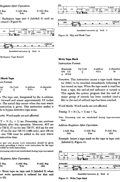
Example. Backspace tape unit 4 (labeled 4) until an IRG is sensed (Figure 9).
Autocoder
label OPERAND
.~
:".
.
~
Assembled Instruction: ~ %U4 B
Figure 9. Backspace Tape Rec-ord
Skip and Blank Tape
Instruction Format.
Mnemonic
SPS CU
A SKP
OpCode
U
A-address %Ux
d-character
E
Function. The tape unit, designated by the A-address, spaces forward and erases approximately 3.5 inches of tape. The actual skip occurs when the next WRITE TAPE instruction is given. This instruction makes it possible to bypass defective tape areas.
Word Marks. Word marks are not affected.
Timing. T
=
N (LI+
1) ms. Processing can continue immediately after this operation. However, 40.5 ms for IBM 729 II, 27 ms for IBM 729 IV, 40.5 ms for IBM 729 V, 27 ms for IBM 729 VI (1460 only), and lOB ms for an IBM 7330 must be added to the next WRITE TAPE instruction time.Notes. The SKIP AND BLANK TAPE instruction should be given
immediately preceding a WRITE TAPE instruction for the tape
unit specified by both instructions.
The processing unit is not interlocked during tape-movement time.
Address Registers After Operation.
I-Add. Reg. NSI
A-Add. Reg. %4x
B-Add. Reg. dbb
Example. Erase tape on tape unit 5 (labeled 5) when the next write operation is ordered for that unit (Figure lO).
Autocoder
~.
label~ti~
i ~I.
.~
~I. 40I I
Assembled Instruction: ~ %U5 E Figure 10. Skip and Blank Tape
Write Tape Mark
Instruction Format.
Mnemonic
SPS CU
A WTM
Op Code
U
A-address %Ux
OPERAND
:~
d-character
M
~
Function. This instruction causes a tape mark charac-ter (8421) to be recorded immediately following the last record on tape. When the tape mark is read back from a tape, the end-of-reel indicator is turned on. This signals the system program that the end of a major group of records has been reached (end-of-file) or the end of utilized tape has been reached. Word Marks. Word marks are not affected.
Timing. T
=
N (LI+
1) ms+
TM •Note. Processing unit not interlocked during tape-movement time.
Address Registers After Operation.
I-Add. Reg. NSI
A-Add. Reg. %4x
B-Add. Reg. dbb
Example. Insert a tape mark on the tape in tape unit 3 (labeled 3), Figure 11.
Autocoder
f ..
label.
:
lS;i~
~". .
~
~.
7.
OPERAND:1
.
~
[image:8.615.82.547.40.744.2]Diagnostic Read
Instruction Format.
Mnemonic SPS (none) A (none)
Op Code
!l
A-address %Bx
d-character
A
Function. This instruction causes the tape unit speci-fied in the A-address to reposition its tape to the next inter-record gap (IRC) without transmitting any data to core storage. If the tape record contains a first character tape mark, the end-of-file (EOF) indi-cator is turned on.
This instruction is useful in skipping records or files on tape. The system is free to proceed with in-ternal processing during the tape movement.
The tape operations are interlocked until the check character of the record being skipped is sensed. Word Marks. Word marks are not affected.
Timing. T = N (LI
+
1) ms+
TM •Note. Processing unit not interlocked during tape-movement time.
Rewind Tape
I nstruction Format.
Mnemonic SPS CU A RWD
Op Code
!l
A-address %Ux
d-character
R
Function. This instruction is usually given after an end-of-reel condition, and causes the selected tape unit to rewind its tape. When the operation is initiated, the tape unit is, in effect, disconnected from the system. Word Marks. Word marks are not affected.
Timing. T = N (LI
+
1) ms. Rewind time is l.2 minutes per 2,400-foot reel for the IBM 729 II, .9 minute for the IBM 729 IV, 1.2 minutes for the IBM 729 V, .9 minute for the IBM 729 VI (1460 only), and 13.3 min-utes for the IBM 7330, but it is not calculated with program time. Processing can continue approxi-mately 10 ms after this instruction is interpreted. Note. Processing unit not interlocked during tape-movementtime.
Address Registers After Operation.
I-Add. Reg. NSI
A-Add. Reg. %4x
B-Add. Reg. dbb
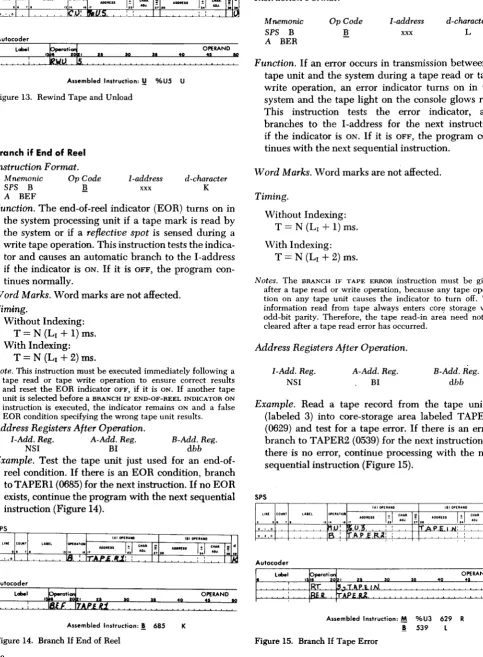
Example. Rewind the tape in tape unit 1 (labeled 1), Figure 12.
Autocoder
la' OPERAND
.
:
~'. ~A •• embled Instruction: ~ %Ul R
Figure 12. Rewind Tape
Rewind Tape and Unload
Instruction Format.
Mnemonic SPS CU
A RWU
Op Code
U
A-address %Ux
d-character
U
Function. This instruction causes the tape unit speci-fied in the A-address to rewind its tape. At the end of the rewind, the tape is out of the vacuum columns, and the reading mechanism is disengaged. The unit is effectively disconnected from the system, and is not available again until the operator restores it to a ready status.
Word Marks. Word marks are not affected.
Timing. T
=
N (LI+
1) ms. Rewind time is 1.2 minutes per 2,400-foot reel for the IBM 729 II, .9 minute for the IBM 729 IV, 1.2 minutes for the 729 V, .9 minute for the 729 VI (1460 only), and 2.2 minutes for the IBM 7330, but it is not calculated with program time. Processing can continue approximately 10 ms after this instruction is interpreted by a system using IBM 729 tape units, or 4.5 seconds in a system using IBM 7330 tape units.Note. Processing unit not interlocked during tape-movement time.
Address Registers After Operation.
I-Add. Reg. NSI
A-Add. Reg. %4x
B-Add. Reg. dbb
Autocoder
label OPERAND
.
:
~'.
.~
:~
.
~
[image:10.607.54.538.80.738.2]Assembled Instruction: Y %U5 U Figure 13. Rewind Tape and Unload
Branch if End of Reel
Instruction Format.
Mnemonic
SPS B
A BEF
OpCode
!!
I-address
xxx
d-character K
Function. The end-of-reel indicator (EOR) turns on in the system processing unit if a tape mark is read by the system or if a reflective spot is sensed during a write tape operation. This instruction tests the indica-tor and causes an automatic branch to the I-address
if the indicator is ON. If it is OFF, the program con-tinues normally.
Word Marks. Word marks are not affected. Tim4ng.
Without Indexing:
T
=
N (LI+
1) ms. With Indexing:T = N (LI
+
2) ms.Note. This instruction must be executed immediately following a
tape read or tape write operation to ensure correct results and reset the EOR indicator OFF, if it is ON. If another tape unit is selected before a BRANCH IF END-OF-REEL INDICATOR ON
instruction is executed, the indicator remains ON and a false
EOR condition specifying the wrong tape unit results.
Address Registers After Operation.
I-Add. Reg. A-Add. Reg.
NSI BI
B-Add. Reg.
dbb Example. Test the tape unit just used for an
end-of-reel condition. If there is an EOR condition, branch to TAPERI (0685) for the next instruction. If no EOR exists, continue the program with the next sequential instruction (Figure 14).
Autocoder
label OPERAND
.
:.~
~.:'.
.
~
Assembled Instruction:! 685 K
Figure 14. Branch If End of Reel
Branch if Tape Error
Instruction Format.
Mnemonic
SPS B
A BER
OpCode
B
I-address
xxx
d-character
L
Function. If an error occurs in transmission between a tape unit and the system during a tape read or tape write operation, an error indicator turns on in the system and the tape light on the console glows red. This instruction tests the error indicator, and branches to the I-address for the next instruction
if the indicator is ON. If it is OFF, the program con-tinues with the next sequential instruction.
Word Marks. Word marks are not affected.
Timing.
Without Indexing: T = N (LI
+
1) ms. With Indexing:T = N (LI
+
2) ms.Notes. The BRANCH IF TAPE ERROR instruction must be given after a tape read or write operation, because any tape opera-tion on any tape unit causes the indicator to turn off. The information read from tape always enters cOre storage with odd-bit parity. Therefore, the tape read-in are~ need not be cleared after a tape read error has occurred.
Address Registers After Operation.
I-Add. Reg. A-Add. Reg.
NSI BI
B-Add. Reg.
dbb
Example. Read a tape record from the tape unit 3 (labeled 3) into core-storage area labeled T APEIN (0629) and test for a tape error. If there is an error, branch to T APER2 (0539) for the next instruction. If
there is no error, continue processing with the next sequential instruction (Figure 15).
SPS
Autocoder
OPERAND
': : : : : i: :
'?rR:
$llli:'~:
:: : : : :': : :
40 ~l ~o
:
:
: :
:~ ::
: Assembled Instruction: M %U3 629 R! 539 l
Magnetic-Tape Operating Considerations
IBM 729 Magnetic Tape Unit
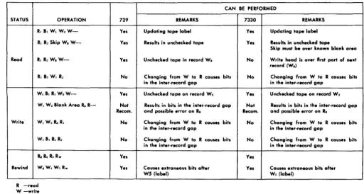
If the 729 is in write status, to change to read status the program must backspace over those records that are to be read. The tape unit must then be changed back to write status (WI, W2 , Wa, Ba, B2 , R2 , Ra, W4, W .... ).
This results in unchecked tape on the first record written after backspace.
The 729 cannot be switched directly from write to read status (WI, W2 , Ra, ~).
If the 729 is in read status, the tape unit can be changed directly from read to write status (RI' R2 ,
Wa, W4 ).
IBM 7330 Magnetic Tape Unit
If the 7330 is in write status, to change to read status the program must backspace over those records that are to be read. The tape unit must then be changed back to write status (WI, W2 , Wa, Ba, B2 , R2 , Ra, W4 ,
W .... ). This results in unchecked tape on the first record written after backspace.
The 7330 cannot be switched directly from write to read status (WI, W2 , Ra, R4)'
If the 7330 is in read status, to change to write status the program must backspace over the last record read and then rewrite that record. The 7330 then continues in write status (RI, R2 , B2 , W2 , Wa, W .... ).
The 7330 cannot be switched directly from read to write status (RI, R2 , W s, W4 ).
Figure 16 is a summary of 1401 and 1460 magnetic-tape operating considerations.
For detailed information concerning magnetic tape and mM magnetic-tape units, refer to the mM
Refer-ence Manual, Magnetic Tape Units, Form A22-6589. Dust or damage to the magnetic tape is the most fre-quent cause of errors detected during write operations. Such imperfections are usually isolated; so, in order to skip the defective section, the system has been pro-vided with an instruction that causes the tape to space forward approximately 3.5 inches when the next write operation is initiated. While the tape is passed, this short length is erased so that extraneous data is not sensed when the tape is read. The tape-write operation continues after the skip is completed.
When writing from load point, a space of 3.5 inches also occurs prior to writing the record, and start time is increased about 27 milliseconds.
Magnetic-Tape Timing
All tape units in a 1401 system are under the control of a tape-adapter unit (a 1461 on the 1460 system). The tape-adapter unit (TAU) can control the operations of only one tape unit at a time. If one tape unit is busy, no other tape unit can be used until all operations on the
CAN BE PERFORMED
STATUS OPERATION 729 REMARKS 7330 REMARKS
R, B, W, W, W-·· R, R, Skip W.
W··--Read R, R,
W.W--R, B. W, W.W--R,
W, B, R, W. W--W, W--W, Blank Area Ra
R-Write WI W,RaR,
W, B, R, R,
Ra II. R, R .. Rewind W.W. W"R ..
R -read W -write B -backspace R .. -rewind
Yes Updating tape label Yes Results in unchecked tape
Yes Unchecked tape in record W.
No Changing from W to R causes bits in the inter-record gap
Yes Unchecked tape on record W. Not Results in bits in the int.r-record gap Recom. and possible error on Ra
No Changing from W to R caus.s bits in the inter-record gap
No Changing from W to R causes bits in the inter-record gap
Yes
[image:11.610.57.570.422.696.2]Yes Causes extraneous bits after W5 (label)
Figure 16. Summary of IBM 1401 and 1460 Magnetic Tape Operating Considerations
Yes Updating tape label Yes Results in unchecked tape
Skip must be over known blank area No Write head is over first part of n.xt
record (W.)
No Changing from W to R caus.s bits in the inter-record gap
Yes Unchecked tape on record W, Not Results in bits in the inter-record gap Recom. and possible error on Ra
No Changing from W to R causes bits in the inter-record gap
No Changing from W to R causes bits in the inter-record gap
Yes
busy one have been completed. The execute time of a tape instruction varies according to the type and model tape units used in the system.
C is the character rate in milliseconds based on the setting of the tape density switch.
N is the number of characters in the record.
CN is record time (number of characters in the rec-ord, times the character rate).
Start time is the time necessary for the tape unit to accelerate to operating speed.
Stop time is the time necessary for the tape unit to decelerate and stop.
Record check time is the time it takes to read or write the check character. This time is based on the read-write head gap (the distance that separates the read and write heads) and the time it takes a single charac-ter written on tape to travel from the write head to the read head.
Load Point Time. When reading or writing from load point, a space of 3.5 inches occurs prior to reading
or writing a record and the start time is increased about 27 milliseconds.
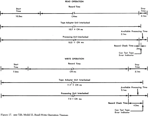
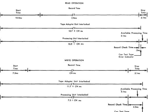
IBM 729 " Tape Timings
During a 729 II read operation, the tape adapter unit or 1461 is interlocked for 10.7
+
CN ms (Figure 17). This includes:10.5 ms - start time
.2 ms - record check time for high-density tape (.6 for low-density tape) CN ms - record time
During the same read operation, the processing unit is interlocked for 10.5
+
CN ms. this includes:10.5 ms - start time CN ms - record time
Therefore, in a tape-read operation, processing can take place during the 2.1 ms stop time. A tape-trans-mission-error condition can be recognized .2 ms after the processing interlock is released. If the tape
trans-READ OPERATION Record Time
Start Stop
I..
Time 1 .. Tim=.I
~·.---~"~I~"'---~J~f---t
.•
---..;~
10.5ms CNms 2.1 ms
Tape Adapter Unit Interlocked
~1~"---~f~J---~-1
10.7 + CN ms
Available Processing Time
2,lm. ,
I..
Processing Unit Interlockedt
I
~·.---~h~(---'-~I~.~~"~
10,5+
CN ms IWRITE OPERATION
Stort Record Time
Record Check Time -+-l \.-.2ms. Can Test Tape---.J Error Indicator
Stop
I-
Time-I ..
I
TimeI
~---~.~---~{,~{---.
..
~~..
~---~-~7.5ms CN ms 5.1ms
I·
~---~fl
Tape Adapter Unit Interlocked 11.7 + CN ms
Available Processing Time !i.lms ,
I •
~---~fl~---~~~""--~--~" Processing Unit InterlockedI
t
I
[image:12.607.40.563.319.714.2]7,5
+
eN msFigure 17, IBM 729, Model II, Read-Write Operation Timings
Record Check Time .... 1 ... - -... --11 4.2ms
t
Can Test Tape ______ ~Error Indicator
.-:
.I
~
:
mission-error-test instruction is given during this .2 ms period, the processing unit is interlocked until the error indicator can be tested.
During a 729 II tape write operation, the tape-adapter unit or 1461 is interlocked for 11.7
+
eN
ms (Figure 17). This includes:7.5 ms - start time
4.2 ms - record check time for high-density tape (4.6 for low-density tape)
eN ms - record time
During the same write operation, the processing unit is interlocked for 7.5
+
eN
ms. This includes:7.5 ms - start time
eN ms - record time
Therefore, in a tape-write operation, processing can take place during the 5.1 ms stop time. A tape-trans-mission-error condition can be recognized 4.2 ms after the processing interlock is released. If the tape-trans-mission-error-test instruction is given during this 4.2 ms
period, the processing unit is interlocked until the error indicator can be tested. The difference between the .2 ms record check time of reading and the 4.2 ms record check time of writing is due to the read-write head gap time (4.0 ms).
For job-timing estimates of tape read-write opera-tions, the nominal formula 10.8
+
eN
ms can be used.IBM 729 IV Tape Timings
During a 729 IV read operation, the tape-adapter unit or 1461 is interlocked for 6.8
+
eN
ms (Figure 18). This includes:6.7 ms - start time
.1 ms - record check time for high-density tape (.4 for low-density tape)
eN ms - record time
During the same read operation, the processing ftnit is interlocked for 6.7
+
eN
ms. This includes:6.7 ms - start time
eN ms - record time
READ OPERATION
Start Record Time Stop
Time
I-
- 1 -I
TimeI
~---~·~---~!f~---~-~.~----~.
6.7msCN ms 2.1ms
I-
Tape Adapter Unit Interlocked~---~h~/---.-~I
6.8+
CN msAvailable Processing Time
I-2.1ms \
~ ________________________________________ pr_o_ce_S_Sin_g~{:~}t __ ln_te_r_1a_c_ke_d ______________________________ .~I~-~~-~1
6.7
+
CN msWRITE OPERATION Record Time Start
Record Check
Time~ll.-.IJS
Can Test Tape Error Indicator
Stop
I-
Time-I-
I
TimeI
~---~+4---~ff~---.·~·~.~--
S ms..
-~.
CN ms 3.8ms
I-
~---~lrS---~·1
Tape Adapter Unit Interlocked 7.8+
CN msAvailable Processing Time
I-
Processing Unit Interlocked 3.8ms \ [image:13.607.40.561.294.702.2]~---~n~---~·~I-~~·I
S+
CN msFigure 18. IBM 729, Model IV, Read-Write Operation Timings
Record Check Time
~
2.8mst
Can Test TapeTherefore, in a tape-read operation, processing can take place during the 2.1 ms stop time. A tape-transmis-sion-error condition can be recognized .1 ms after the processing interlock is released. If the tape-transmis-sion-error-test instruction is given during this .1 ms period, the processing unit is interlocked until the error indicator can be tested.
During a 729 IV tape tuite operation, the tape-adapter unit or 1461 is interlocked for 7.8
+
eN
ms (Figure 18).This includes:
5 ms - start time
2.8 ms - record check time for high-density tape (3.0 for low-density tape) CN ms - record time
During the same write operation, the processing unit is interlocked for 5
+
eN
ms. This includes:5 ms - start time CN ms - record time
Therefore, in a tape-write operation, processing can take place during the 3.8 ms stop time. A tape-trans-mission-error condit~ can be recognized 2.8 ms after the processing interlock is released. If the tape-trans-mission-error-test instruction is given during this 2.8 ms period, the processing unit is interlocked until the error indicator can be tested. The difference between the .1 ms record check time of reading and the 2.8 ms rec-ord check time of writing is due to the read-write head gap time (2.7 ms).
For job-timing estimates of tape read-write opera-tions, the nominal formula 7.3
+
eN
ms can be used.IBM 729 V Tape Timings
During a 729 V read operation, the tape-adapter unit or 1461 is interlocked for 10.7
+
eN
ms (Figure 19).READ OPERATION Record Time
Start Stop
Time
I
}im:'1
~---~~---~f~f---+-~.--.~~-I ..
10.5ms--I-CNms 2.1ms
Tape Adapter Unit Interlocked
~---~.f~f---~·I
I-
10.7 + CN msAvailable Processing Time
I-2.1ms ~
Processing Unit Interlocked
~---~/,~'---.~-~I~-~~·~I
10.5+
CN msWRITE OPERATION
Record Check
Time--.ll..--.2ms. Can Test Tape---1 Error Indicator
Start
I ..
Time-I ..
7.5ms
Record Time Stop
~---'~'---~{,f'---"-~1~_~~T~im~e~
__~_
1CN ms 5.1ms
I-
~---~{~f---~_I
Tape Adapter Unit Interlocked 11.7 + CN msAvailable Processing Time
5.1ms ,
[image:14.612.42.552.308.693.2]I -
~---~ff~---'-~I~-~~--~·I
Processing Unit Interlocked 7.5+
CN mst
Figure 19. IBM 729, Model V, Read-\Vrite Operation Timings
,
This includes:
10.5 ms - start time
.2 ms - record check time for high-density tape (.6 for low-density tape)
eN ms - record time
During the same read operation, the processing unit is interlocked for 10.5
+
CN ms. This includes:10.5 ms - start time
eN ms - record time
Therefore in a tape-read operation, processing can take place during the 2.1 ms stop time. A tape-trans-mission-error condition can be recognized .2 ms after the processing interlock is released. If the tape-trans-mission-error-test instruction is given during this .2 ms period, the processing unit is interlocked until the error indicator can be tested.
During a 729 V write operation, the tape-adapter unit or 1461 is interlocked for 11.7
+
eN
ms (Figure 19). This includes:7.5 ms - start time
4.2 ms - record check time for high-density tape (4.6 for low-density tape)
During the same write operation, the processing unit is interlocked for 7.5
+
eN
ms. This includes:7.5 ms - start time
eN ms - record time
Therefore in a tape-write operation, processing can take place during the 5.1 ms stop time. A tape-trans-mission-error condition can be recognized 4.2 ms after the processing interlock is released. If the tape trans-mission-error-test instruction is given during this 4.2 ms period, the processing unit is interlocked until the error indicator can be tested. The difference between the .2 ms record check time of reading and the 4.2 ms rec-ord check time of writing is due to the read-write head gap time (4.0 ms).
For job-timing estimates of tape read-write opera-tions, the nominal formula 10.8
+ eN
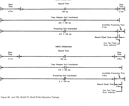
ms can be used.IBM 729 VI Tape Timings
During a 729 VI read operation, the tape-adapter unit or 1461 is interlocked for 6.8
+
eN
ms (Figure 20). This includes:6.7 ms - start time
.1 ms - record check time for high-density tape (.4 for low-density tape)
eN ms - record time
During the same read operation, the processing unit is interlocked for 6.7
+
eN
ms. This includes:6.7 ms - start time
eN ms - record time
Therefore in a tape-read operation, processing can take place during the 2.1 ms stop time. A tape-trans-mission-error' condition can be recognized .1 ms after the processing interlock is released. If the BRANCH IF
TAPE ERROR instruction is given during this .1 ms period,
the processing unit is interlocked until the error indi-cator can be tested.
During a 729 VI write operation, the tape-adapter unit or 1461 is interlocked for 7.8
+
eN
ms (Figure 20). This includes:5 ms - start time
2.8 ms - record check time for high-density tape (3.0 for low-density tape)
During the same write operation, the processing unit is interlocked for 5
+
eN
ms. This includes:5 ms - start time
eN ms - record time
Therefore in a tape-write operation, processing can take place during the 3.8 ms stop time. A tape-trans-mission-error condition can be recognized 2.8 ms after the processing interlock is released. If the tape-trans-mission-error-test instruction is given during this 2.8 ms period, the processing unit is interlocked until the error indicator can be tested. The difference between the .1 ms record check time of reading and the 2.8 ms rec-ord check time of writing is due to the read-write head gap time (2.7 ms).
For job-timing estimates of tape read-write opera-tions, the nominal formula 7.3
+ eN
ms can be used.IBM 7330 Tape Timings
During a 7330 tape-read operation, the tape-adapter unit or 1461 is interlocked for 20.5
+
CN ms (Figure 21). This includes:10.3 ms - start time 9.8 ms - stop time
.4 ms - record check time for high-density tape (1.0 ms for low-density tape)
eN ms - record time
During the same read operation, the processing unit is interlocked for lOA
+ eN
ms. This includes:10.3 ms - start time
.1 ms - part of the .4 ms record check time
eN ms - record time
READ OPERATION
Start Record Time Stop
I-
Time-I-
(~I
Time1
I
-
-
-6.7ms CN ms 201ms
I-
Tape Adapter Unit Interlockedf.'
I-I
608
+
CN msAvailable Processing Time 201ms
\
I-
Processing Unit Interlocked ~i-I
-I-II
607
+
CN msRecord Check Time
----+-Il-olJ
Can Test Tape Error Indicator WRITE OPERATION
Record Time
Start Stop
I-
Time-I-
(f
I
Time-I
,
"
..5 ms CN ms 308ms
Tape Adapter Unit Interlocked
I-
H
- 1
708
+
CN msAvailable Processing Time Processing Unit Interlocked 308ms
\
I-
ff
-I"
-I
5
+
CN ms [image:16.607.35.554.60.483.2]Record Check Time
o
H
208mst Can Test Tape Error Indicotor Figure 200 IBM 729, Model VI, Read-Write Operation TimingsDuring a 7330 tape-write operation, the tape-adapter unit is interlocked for 20.3
+
CN ms (Figure 21). This includes:5.0 ms - start time 606 InS - stop time
807 ms - record check time for high-density tape (903 ms for low-density tape) CN ms - record time
During the same write operation, the processing unit is interlocked for 5
+
CN ms. This includes:5.0 ms - start time
CN ms - record time
Therefore, in a tape-write operation, processing can take place during the 15.3 ms stop time. A tape-trans-mission-error condition can be recognized 8.7 ms after
the processing interlock is released. If the tape-trans-mission-test instruction is given during this 8.7 ms period, the processing unit is interlocked until the error indicator can be interrogated. The difference between the .4 ms record check time of reading and the 8.7 ms record check time of writing is due to the read-write head gap time (8.3 ms).
For job-timing estimates of read operations in either 0
high- or low-density, use the formula 20.1
+
C (N+
7) ms, where the factor C (7) is the record check time.For job-timing estimates of write operations in either high- or low-density, use the formula 19.9
+
C (N+
7) ms, where the factor C (7) is the record check time, and 8.3 ms of the 19.9 ms is the read-write head gap time.r'
READ OPERATION Record Time
Start Stop
~1~
.. __
---T-im-e---~~~I~~~--
__ ---__--4:/~/---~~~I 11~
..
---Ti-m-e---_.~
...1
10.3 ms CN ms Ams 9.8 ms
Tape Adapter Unit Interlocked
~1·"---2-0-.5-+-lJ~C-N-m--s---~
Available Processing Time10.1 ms
I.
Processing Unit Interlocked~-.---1J~---~
10.4
+
CN ms:-::I:=_-
_____
can Test Tape .3 ms Error IndicatorWRITE OPERATION
Start Record Time Stop
I ..
Time~
I ..
5 ms
I
I
Time
~~---~~.---~J,~(---~~~~.---~~~~'---~~"'I
CN ms 8.7ms 6.6msI ..
Tape Adapter Unit Interlocked~~---~fJ---~
20.3+
CN msAvailable Processing Time 15.3 ms
,..
Processing Unit Interlocked
~---I}~---'~---~
[image:17.610.44.570.81.663.2]5
+
CN ms 8.7msFigure 21. IBM 7330 Read-\Vrite Operation Timings
IBM 7340 Hypertape Drive
The IB!\f Hypertape Drive, Model 2, when used with
the IB!\[ 1401 and 1460 Data Processing Systems, makes
it possible to read and write magnetic tape at speeds of 34,000 alphameric characters a second and 68,000 nu-meric characters a second. With this input/output magnetic-tape facility, data in the fonn of 8 data bits and 2 parity bits, is recorded at a density of 1,511 alpha-meric characters per inch. Where nualpha-meric packing is possible and is used, the recording density is 3,022 digits to the inch.
Instructions
All operations performed by the IBM 7641 Hypertape Control Unit and the IBM 7340 Hypertape Drive, Model 2, result from four basic instructions: Read, \Vrite, Control, and Sense.
READ and WRITE instructions initiate movement of data between the processing unit and the tape units.
The CONTROL instruction initiates the transfer of or-ders (as data) from the core-storage area to the control unit.
The SENSE instruction initiates the movement of status conditions (as data) from the control unit to core storage. After this status data is moved to the processor, it is tested by the stored program (some conditions re-quire operator intervention). The SENSE instruction is used for detection of errors and unusual conditions.
Start Control
Instruction Format.
Mnemonic
SS
OpCode
K
d-character
F
Function. The START CONTROL instruction (K with an F d-character) alerts the control unit that the following MOVE and LOAD instruction contains a control order
at the core-storage location specified in the B-address. When the MOVE or LOAD instruction is executed, the control order will be moved from core storage to the control unit. The control orders are transmitted as either two or three 4-bit characters. The first two characters indicate the operation code, and the third character indicates the address of the Hypertape Drive Unit (the third character is used for select only).
After the order is transmitted to the 7641, it is de-coded and executed by the control unit. For complete description of hypertape control orders, refer to Fig-ure22.
\Vord Marks. Word marks are not affected.
Timing. Refer to Figure 22.
Start Sense
Instruction Format.
Mnemonic
SS
Op Code
K
d-character
G
Function. The START SENSE instruction (K with a G d-character) alerts the control unit that the following MOVE or LOAD instruction will move status data from the 7641 to the core-storage position specified in the B-address. This data reflects the status of the con-trol unit and the currently selected hypertape drive. These status conditions are set in the 7641 and are always available to the computer. The status indica-tors reflect error and other conditions that the com-puter should be aware of. The status indicators are retained by the 7641 until reset by the initiation of a subsequent read, write, or control operation.
ffiar-...
~
::l
~
~
Q
[
f
o·
iil
,.
4
~
•
The control instruction (~ Op Code, and an F d-character) is given to initiate a control operation. The MOVE or lOAD instruction will then move the control order numeric code from the computer to the control unit. The B-address of the MOVE and lOAD instruction specifies the core storage location where the control order is stored. The d-character of W (Write) is used because the transmission of data is from the computer to the control unit. If x in the numeric code is a group mark with a word mark, the system will terminate the transmission of control data and procede with the next sequential instruction. Any other BCD code configuration in the x position will be ignored by the 7641 Control Unit; the system will not proceed to the next sequential instruction until the control unit signals an END condition.
INSTRUCTION CONTROL NUMERIC
Op code I A - address I B - address I d - character ORDER CODE OPERATION TK ms Morl %11 xxx W Set Normal 01x
(Unpacked) These control orders will condition the control unit to process tape in (B -address specifies high -order core Storage- Set Packed either the unpacked, packed, or 7074 packed mode. They will take
position where numerical code for the particular Mode 02x precedent over the setting of the Tape Record Format Switch. .0575 control order is stored. ) Pressing the Start Reset Key on the system operating panel will return
Set 7074 control to the switch. Packed Mode 03x
Select O6n This order selects the addressed Drive and signals END to the system. The third character (n) is 0, 1, 2, or 3. .065 ms This order initiates a rewind operation for the selected Drive, signals
END to the processing unit and places the Drive in busy status until
Rewind 30x rewind is completed. Operation is terminated when BOT marker is 3.06 ms sensed. Attention is signaled to the computer upon successful
completion of the operation.
This order first initiates a rewind operation for the selected Drive, Rewind
31x and upan sensing the BOT marker, an unload operation is initiated. 3.06 ms Unload END is signaled to the system at the beginning of the rewind
operation. Attention signaled upon successful completion.
Erase long This order causes forward spacing and erases eight inches of tape
32x for the selected Drive. END is signaled upan successful completion 366.00 ms Gap of the operation.
Write Tape 33x This order causes the selected Drive to write a tape mark. Inter-record gaps precede and follow the tape mark record. END is 23.8 m s Mark signaled to the system upon successful completion of the operation.
This order causes the selected Drive to backspace over One record. 11.433+ (.0147 x number of Backspace 34x The END signal is sent to the computer upon successful completion
!
I
I
of the operation. characters in record) m s j
This order causes the selected Drive to backspace over successive 11.785+{11.179'x number of! Backspace
35x records until a tape mark is sensed. END is signaled to the records)+{.0147 x total File computer upon completion of the operation. (Unusual End if BOT number of characters in all
sensed.) records) m s
Space 36x This order causes the selected Drive to space forward over one 16.41+ {.0294x number of record. END is signaled upon completion of the operation. characters in record) m s I
This order causes the selected Drive to space forward over successive 17.115 + {22.358 x no. of '! Space File 37x records until a tape mark is sensed. END i. signaled upon completion records )+{.294 x total no. of
of the operation. (Unusual End if EOT sensed.) char. in all records) m s
Addre. Registers After Operation
I - address Reg. A - address Reg. B -address Reg.
NSI %91 B+4
Timing T=. 161 ms (if x is group mark with a word mark)
T=.1035+TKms (if x i. BCD code configuration other than group mark - with a word mark) TK ms = Tape Control Unit Time
acters unless tenninated by a stop from the com-puter. For a complete description of the sense status conditions, refer to Figures 23 and 24.
Start Read
Instruction Format.
Mnemonic CU
Op Code
U
A-address
%Il
d-character E
Word Marks. Word marks are not affected.
Timing. Refer to Figure 23.
Function. The START READ instruction alerts the control
unit that the following MOVE and LOAD instruction
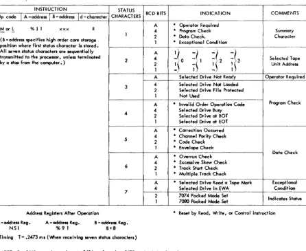
The sense instruction (~ OP code, and a G d-character) is given ta initiate a sense operatian. The MOVE or lOAD instruction will then move the status data from the control unit to the computer. The B-oddress of the MOVE and lOAD instruction specifies the core storage location where the first status character is stored. The d-character of R (Read) is used because the transmission of data is from the control un i t to the computer.
INSTRUCTION STATUS
Op code
I
A -addressI
B -addressI
d -character CHARACTERS BCD BITS INDICATION COMMENTS A * Operator RequiredMorl %11 xxx R 4 * Program Check Summary
-
-1 2 * Data Check. Character
(B -address specifies high order core storage
1 • Exceptional Candition position where first status character is stored.
All seven status characters are sequentially A
~i
0=1
=1
f!'
transmitted to the processor, unless terminated2 4 Selected Tape
by a stop from the computer. ) , 1
~~
2 2
~~ ~~
Unit Address1
A Selected Drive Nat Ready Operator Required 3 4 Selected Drive Not loaded
2 Selected Drive File Protected 1 Not Used
A • Invalid Order Operation Code Program Check 4 4 2 Selected Drive Busy Selected Drive at BOT
1 Selected Drive at EOT A • Correction Occurred
5 4 • Channel Parity Check
2 • Code Check 1 • Enve lope Check
Data Check A • Overrun Check
4 • Excessive Skew Check 6 2 • Track Start Check
1 • Multiple Track Check
A * Selected Drive Reod a Tape Mark Except i ona I 4 Selected Drive in EWA Condition 7
7074 Packed Mode Set
2 Indicates Status
1 7080 Packed Mode Set
Address Registers After Operation • Reset by Read, Write, or Contral instruction I - address Reg. A - address Reg. 8 - address Reg.
NSI %91 8+8
Timing T = .2473 m I (When receiving seven status characters)
[image:20.613.43.490.336.701.2]NOTE: For 1460 operatian, subtract .0494 ml from the .2473 ml in timing formula.
Figure 23. Sense Operation
The summary status character is set if any of the status conditions are present. This character can be interrogated by the stored program; if no bits are set I interrogation of the remaining status characters is not necessary.
CHARACTER BIT CONDITION COMMENTS
A Selected Drive not ready. Operator required
Selected Drive is not loaded.
Selected Drive is file-protected and a WRITE instruction is given.
4 Selected Drive is busy (Rewinding). Program check Selected Drive is at BOT marker, and a backspace or backspace file order was given.
Selected Drive is at EOT marker, and an order requiring forward motion was given. Inva lid operation code.
Multiple track check: this indicates more than one envelope check.
Channe I parity: parity error detected during transmission of data from processing
1 unit to 7641.
(Summary character) Code check: while reading, a malfunction occurred that produced an uncorrectable
2 error • Data check Envelope check: during a write operation, one or more bit tracks were in error.
Overrun check: this indicates that the system failed to receive or transmit a character within the allotted time for normal character transmission. This error
can OCcur after a read or write operation.
Excessi ve skew: this indicates that the bits on tape do not fall within the Hypertape character-pasition limits.
Track start check: this indicates a circuit fai lure in a bit track.
[image:21.612.56.515.73.288.2]1 Selected drive read a tape mark: indicates a tape mark was sensed while reading. Exceptional condition Selected drive in EWA: indicates End Warning Area Marker is sensed when writing.
Figure 24. Summary Status Characters
will move data read from tape to core storage, start-ing with the position specified by the B-address.
with a word-mark in core storage. Refer to Figure 25 for detailed description of the read operation. The read operation is stopped by sensing an
inter-record gap (IRG) on tape, or sensing a group-mark
Word Marks. Word marks are not affected.
Timing. Refer to Figure 25.
INSTRUCTION
Op code
I
A - addressI
B - addressI
d - character FUNCTION OPERATIONThis instruction causes the selected Drive to physically start moving U %11 E Start Read tape. The following MOVE or LOAD instruction must be given
-
within 12 milliseconds after the actual movement of tape starts. If 12 milliseconds is exceeded, an overrun check condition may occur. This instruction causes the selected Drive to read tape and store the data in core storage starting at the location specified by the B-address. The B-address specifies the high-arder position of the M or L-
%11 xxx R Read Tape record. The read operation is terminated by sensing an inter-recordgap on tape, or sensing a group-mark with a word-mark in core storage. In the unpacked mode if the L Op code is used, word marks on tape wi II be transferred to core storage.
Address Register After MOVE or LOAD Operation I - address Reg. A - address Reg. B - address Reg.
NSI %91 Group - mark + 1
Timing is computed from initiation of the Start Read instruction to the completion of the MOVE or LOAD instruction. Timing for unpacked tape: T; 15.343+{ .0294 x number of characters in record) ms, if 1401 disconnects
T; 16.526+{ .0294 x number of characters in record) ms, if 7641 disconnects • Timing for packed numeric tape: T; 15.343+{ .0147 x number of characters in record) ms, if 1401 disconnects T; 16.526+{ .0147 x number of characters in record) ms, if 7641 disconnects
* If combination of alphabetic and packed numeric tape is processed, the character rate of .0147 ranges from .0147 to .0294 ms.
NOTE: If tape is at BOT, add 336 ms to timings in above formulas.
For 1460 operation, subtract .033 ms from bath the 15.343 ms and the 16.526 m s in timing formulas.
[image:21.612.53.509.426.710.2]INSTRUCTION
Op code
I
A - addressI
B - addressI
d - character FUNCTION OPERATIONThis instruction causes the selected drive to physically start moving U % I I D Start Write tape. The fallowing MOVE or lOAD instruction must be given within 14 milliseconds after the actual movement of tape starts. If 14 milliseconds is exceeded, an overrun check condition may occur. This instruction causes the selected drive to write tape starting from the core storage position specified by the B -address. The B - address Morl % I 1 xxx W Write Tape specifies the high -order position of the record. The write operation
-
is terminated by sensing a group - mark with a word -mark in core storage. In the unpacked mode if the l Op code is used, word marks wi II be written on tape.Address Registers After MOVE or lOAD Operation I - address Reg. A -address Reg. B - address Reg.
NSI %91 Group - Mark + 1
Timing is computed from initiation of the Start Write instruction to the completion of the MOVE or lOAD instruction. Timing for unpacked tape. T= 15.295+( .0294 x number of characters in record) ms
• Timing for packed numeric tape. T= 15.295+( .0147 x number of choracters in record) ms
.
If combination of olphabetic and packed numeric tape is written, the character rate of .0147 ranges from .0147 to .0294 m s •NOTE: If tape is at BOT, add 336 ms to timings in above formulas. The END stotus conditions are not avoilable until 7.873 ms after completion of the MOVE or lOAD operation.
[image:22.607.37.496.46.313.2]For 1460 operation, subtract .033 ms from the 15.295 ms in timing formula.
Figure 26. Write Operation
Start Write
Instruction Format.
Word Marks. Word marks are not affected.
Mnemonic
CU Op Code U
A-address %11
d-character
D
Function. The START WRITE instruction alerts the con-trol unit that the following MOVE and LOAD instruc-tion will move data from core storage, starting with the position specified by the B-address, to the control unit on the hypertape drive.
Timing. Refer to Figure 27.
Response
Instruction Format.
Mnemonic SSB
OpCode
K
I-address (xxx)
d-character x The write operation is stopped by sensing a
group-mark with a word-group-mark in core storage. Refer to Fig-ure 26 for detailed description of the write operation. Word Marks. Word marks are not affected.
Timing. Refer to Figure 26.
Function. This RESPONSE instruction resets the Attention indicator if ON with a B d-character and resets the End indicators if ON with Ed-character.
Branch if Indicator On
Instruction Format.
Mnemonic BIN
OpCode B
I-ciddress xxx
d-character x
Function. The d-character in the BRANCH IF INDICATOR ON instruction specifies the indicator tested. If the indicator is ON, a branch to the specified I-address occurs. If the indicator is OFF, the next sequential in-struction is taken. Figure 27 shows the inin-structions, d-characters, and the conditions tested.
The
K
(xxx) E instruction must be executed before another hypertape operation is initiated. Refer to Figure 27 for detail information.Word Marks. Word marks are not affected.
Op code
INSTRUCTION
II - address I d - Character CONDITION
,
Test for Unusual End. This indicatar is set ON if any unusual condition occurs such as selected B xxx 1 drive nat ready, busy, not loaded, file protected (if write instruction given), at BOT, at EOT,- in end warning area, read I] tape mark, read and write errors. (See Note)
----~~---~---~-~---B xxx 2 Test for Norma I End. This indicator is set ON if the operation has been successfully completed
- as instructed and no unusual conditions occurred. (See Note)
Test for 7641 Busy. This indicator is set ON if the 7641 Control Unit is busy. This instruction B xxx 3 should be given before a read, write, control, or sense instruction to make sure the control is
- not busy, and should be given again after these instructions are given to make sure the 7641 has become busy.
B xxx 4 Test for Attention. This indicator is set ON when the selected drive has completed a rewind operation and is now in a Ready Status, or if the drive has been put in 0 Ready Status manually.
-K (xxx)
-
B Attention Response. This instruction resets the Attention indicator if on.K (xxx) E
-
End Response. This instruction resets the End or Unusual End indicators if on. (See Note) Address Register After OperationI-address Reg. A - address Reg. B -address Reg.
NS I B I B I (! ( III ) d instruction)
NSI B I dbi (~( III) d instruction)
Timing T= .01J5(LJ+ I) ms (For 1460 operation replace .01J5mswith .000ms)
[image:23.613.58.518.45.304.2]NOTE: A branch on either ~(III) 1 or ~(III) 2 must be successful prior to initiating the !S(xxx) instruction. The !S (xxx) E instruction must be executed before initiating another Hypertape operation.
Figure 27. Branch-If-Indicator On and Response
,
IBM 1011 Paper Tape Reader
The IBM 1011 Paper Tape Reader for the IBM 1401, 1410, 1440, and 1460 Data Processing Systems is an input device controlled by stored programs in the same manner as other input-output equipment (card reader, card punch, and printer).
Information punched in paper tape can be read by the IBM 1011 directly into any area of 1401, 1440, or 1460 core storage. Any character punched in 5-track telegraphic, 8-track IBM, or many other paper-tape codes can be encoded into any valid 1401/1440/1460 character through the flexibility of control-panel wiring on the tape reader.
Instructions
The instructions described in this section are for the IBM 1401, 1440, and 1460 Data Processing Systems.
Read from Paper Tape
Instruction Format.
Op Code
M
A-address
%Pl
B-address
BBB d-character R
Function. This instruction causes data to be read from the paper tape reader into core storage, beginning at the B-address.
The M Op code specifies that the operation will be pedormed in the move mode. When the M operation code is used, word marks are not transferred into core storage with the data read from the paper tape, and word marks in the core-storage paper-tape read-in areas are undisturbed. The A-address, %Pl, is the code assigned to both the IBM 1011 Paper Tape Reader and the IBM 1012 Tape Punch.
The B-address specifies the core-storage position (high-order) that receives the first character of infor-mation from the paper-tape reader. The succeeding characters are read into the adjacent higher-num-bered core-storage positions.
The d-character R specifies a read operation. The read operation ends either by detection of a group-mark with a word-group-mark in core storage (signifies the end of the read-in area), or by reading an EOR (end-of-record character) character punched in the tape.
Any paper-tape character can be used as an record character. Wiring the assigned end-of-record character decode-exit hub to the end-of-end-of-record IN hub terminates the paper-tape read operation and enters a group mark in core storage.
Note. If a group-mark with a word-mark in core stor-age is used to terminate the paper-tape-read opera-tion, the character read into the A-register, when the group-mark with a word-mark is sensed, will be lost. Word Marks. Word marks are not affected.
Timing (T = N (LJ
+
1) ms+
record transmission time.N = .0115 (1401), .0111 (1440), .006 (1460). Address Registers After Operation.
I-Add. Reg. NSI
A-Add. Reg. %71
B-Add. Reg. B
+
message length+
1Read from Paper Tape with Word Marks
Instruction Format.
OpCode
k
A-address
%Pl
B-address BBB
d-character
R
Function. This instruction is similar to the READ FROM
PAPER TAPE instruction, except that word marks are
removed from the paper-tape read-in area in core storage, and word-separator characters read from the paper-tape reader causes the insertion of a word mark in core storage with the next character read from the 1011. The
1
Op code specifies that the operation will be pedormed in the load mode, which results in the word mark control already discussed. Word Marks. Word marks are removed from thepaper-tape read-in area in core storage, and word-separator characters read from the paper-tape reader causes a word mark to be associated with the next character read from the 1011.
Timing. T
=
N (LI+
1) ms+
record transmission time. Address Registers After Ope1'ation.I-Add. Reg. NSI
A-Add. Reg. %71
Branch if Input/Output Indicator On
Instruction Format.
OpCode
B
I-address
III
d-character
1
Function. When a parity error is detected during a read operation, the PE hub provides an error output (8-track tape only). When the error condition occurs, the error character is suppressed and a special output is made available on the paper-tape-reader control panel. This signal can be used to either substitute a unique error character, or delete that position. Refer to CONTROL and SPECIAL PURPOSE hubs in IBM 1011
Paper Tape Reader, Form A26-5754.
1b.e detected parity error also turns on the input-output error latch in the system. A paper-tape-read operation should always be followed by a BRANCH IF INPUT-OUTPUT INDICATOR ON instruction. 1b.is instruc-tion checks the status of the input-output error latch.
If the latch is ON, the system branches to the error subroutine. If the latch is OFF, the program goes to the next sequential instruction.
Word Marks. Word marks are not affected.
Timing. No Branch:
T=N(Lr +1)ms.
Branch (without indexing):
T = N (L\
+
1) ms. Branch (with indexing):T = N (Lr
+
2) ms.Address Registers After Operation.
I-Add. Reg. A-Add. Reg. No Branch
(no indexing) NSI BI Branch
(no indexing) NSI BI Branch (with
indexing) NSI BI
B-Add. Reg.
dbb
Blank
NSI
Branch if Paper Tape Reader Ready
Instruction Format.
Op Code
B
I-address
III
d-character 2
Function. This instruction checks the status of the tape-reader-ready indicator. If the paper-tape reader is not ready, when tested, the program goes to the next sequential instruction. If the paper-tape reader is ready, when tested, the program branches to the sub-routine that begins at the core-storage position speci-fied by the instruction I-address.
Word Marks. Word marks are not affected.
Timing.
No Branch:
T = N (Lr
+
1) ms.Branch (without indexing):
T = N (Lr
+
1) ms. Branch (with indexing):T = N (Lr
+
2) ms.Address Registers After Operation.
I-Add. Reg. A-Add. Reg. B-Add. Reg.
No Branch (no indexing)
Branch (no indexing)
Branch (with indexing)