Planning domain definition using GIPO
R . M . S I M P S O N , D . E . K I T C H I N and T . L . MCC L U S K E Y
School of Computing and Engineering, The University of Huddersfield, Huddersfield HD1 3DH, UK; e-mail: [email protected]
Abstract
In this paper an object-centric perspective on planning domain definition is presented along with an overview of GIPO (graphical interface for planning with objects), a supporting tools environ-ment. It is argued that the object-centric view assists the domain developer in conceptualizing the domain’s structure, and we show how GIPO enables the developer to capture that conceptualiza-tion at an appropriate and matching conceptual level. GIPO is an experimental environment which provides a platform for exploring and demonstrating the range and scope of tools required to support the knowledge engineering aspects of creating and validating planning systems, both for classical pre-condition planning and hierarchical planning. GIPO embodies the object-centric view, leading to a range of benefits typically associated with object-oriented methods in other fields of software engineering such as highly visual development methods, code reuse and efficient, reliable development.
1 Introduction
This article postulates an object-centricmedium for the formulation of planning domain defini-tions, and describes GIPO (graphical interface for planning with objects), a tools environment which embodies this approach. Our work is concerned with simplifying the task faced by know-ledge engineers when developing problem and domain definitions suitable for use with domain-independent planning software. The aspect of knowledge engineering supported by the object-centric approach is that of the formulation of the problem scenario. Its use presupposes that a problem scenario appropriate for the deployment of domain-independent planning technology has already been identified and analysed, but has not been formally encoded in a planning speci-fication language. Formulating the domain model normally requires great skill and understanding of the specification language.
theDock Worker Robots(DWR) example, a domain in which automated cranes and robot trucks manage and transport containers around a shipping dock port (for a detailed description of the DWRexample see Ghallab et al., 2004). The domain can be modelled by describing the changes that can happen to the object sorts, that is, the robots, the containers and the cranes. Tradition-ally, creating specifications for AI planning domains involved the author focusing on the actions available to solve given problem instances. These actions are modelled by parameterized struc-tures called action (or operator) schema (we use the term actions in this paper). In the object-centric view, the focus is on the possible significant changes of state that the objects populating the problem scenario can make. In the DWR world the focus changes from considering, for exam-ple, how the ‘lifting’ of the robot arm may be specified to describing the states of the robot arm as ‘free’ or ‘busy’, and the states of the containers as ‘lifted’ or ‘stacked on a container pile’ or ‘loaded on a ship’. Action definitions are then synthesized from the component descriptions of the changes that occur to the individual objects. In this way, the object-centric method provides guidance on how the author can create action definitions. In this manner the domain definition task has, we believe, been decomposed into smaller more manageable sub-tasks. The object-centric view is also capable of being captured by state machine representations which can be a useful aid in understanding.
A method for formulating domain definitions based on the object-centric idea was introduced by McCluskeyet al. (1996); McCluskey & Porteous, (1997), and was linked to the development of the definition language OCL, later refined intoOCLh(McCluskey & Kitchin, 1998). The object-centric approach has its roots inOCLbut is capable of being lifted above the particular language that the definition is encoded in. Tool support enables the domain definition to be translated into other languages, principally PDDL, the dominant language used for the communication of domain definitions in AI planning (Ghallab et al., 1998; Fox & Long, 2001).
The current version of GIPO has two major operating modes. The standard mode allows the creation of classical planning domains. The internal representation allows the capture of domains of the complexity of those describable in PDDL version 1.7 without the use of any hierarchical task network (HTN) features. The second major mode enables HTN planning and is supported by theHyHTNplanner (McCluskey et al., 2003). In both modes the tool set contains graphical editors to assist in the creation of the domains, built-in planners to solve developed problems and animators to graphically inspect the plans produced. Manual steppers are provided by GIPO in both modes to assist in dynamically validating domain specifications. The steppers allow the user to create plans for well-understood example problems and inspect points of failure in cases where no plan (or no correct plan) is generated by the available planners. GIPO has an open API to link public domain AI planning engines to the system. Planning systems that process PDDL domain and problem descriptions from a command line interface can be executed by planner-specific scripts from within the GIPO environment. After a plan is generated it is returned to GIPO and loaded into the plan animator allowing the solution to be visualized. We aim to develop GIPO in step with the expressiveness of standard AI planner domain description languages to preserve this external planner link.
This paper presents an introduction to the underlying philosophy of the ‘object-centric’ view and shows how it supports a visual state machine type representation. We show the essential structure of the state machine representation and demonstrate how it maps to PDDL domain definitions. In the second part of the paper, an overview of the scope of the GIPO tool set is presented and we show how it capitalizes on the underlying ‘object-centric’ view.
2 The object-centric view
2.1 Ontological assumptions of the object view
This set of dynamic objects can be partitioned into subsets such that each member of a subset is distinguishable, relative to the planning task, by name only. Each object belonging to such a sub-set is capable of making the same changes. For each of these dynamic subsub-sets of objects, which we callsorts(deriving from many-sorted logics; Manzano, 1993) the primary changes they undergo can be described by identifying named states that they change between. Additionally, for each suchsortthere may be properties, which are functions on an object’s state, that characterize the sort’s individuals. These properties may be static in the sense that they do not change during plan execution or they may be dynamic and are subject to change. Changes either to an object’s state or to its dynamic properties are brought about by actions that can be controlled by the plan-ning executive. A change may be accompanied by aconstraint that requires the properties of the object to meet some condition. The distinction between what is classified as a named state and what as a property is to some extent pragmatic. In many cases the distinction will be intuitively obvious. A ‘robot truck’ may be described as having states ‘available’ or ‘out of service’ but have the property of being located. Factoring out properties of objects allows for a more succinct state machine representation of an object’s ‘life history’ as described in the following text.
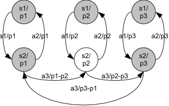
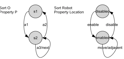
Given the above categorization of planning domain scenarios, we can represent the possible changes objects may make during plan execution with a form of finite state machine. Consider an object o1 of sort O capable of being in state s1 or s2. Objects of sort Ohave a property P that can take on the values p1, p2 or p3. Let us assume that an object of sort O can change between statess1 ands2 by performing actiona1, and between s2 and s1 by performing action a2, and that during these changes the property P does not change. Such a scenario could be depicted by three disconnected state machines. Further, if we allow actiona3 to change the pro-pertyPfromp1 top2 or fromp2 top3 or fromp3 top1, the three connected state machines could be shown as in Figure 1. If we have multiple objects of sortOthen their potential changes would each be shown on a structurally identical state machine. Such forests of state machine diagrams are clearly unwieldy but they can be simplified into a compact form: we can use one diagram to represent each object of the same sort, and we can remove the duplication resulting from different property values. The result of such simplification allows us to represent the same information in the state machine shown in Figure 2(a), where the constraint on actiona3 is given by the relation, next(p1,p2),next(p2,p3),next(p3,p1). In this diagram, we present along side the abstract machine a possible realization within the DWR domain where we have robots that require to be enabled before they can move between adjacent locations. The arrows labelled only by action names are assumed to leave properties of the objects unchanged. The ‘abstract state machine’ diagrams form the basis of the history view of planning domains. We call such diagrams ‘object life history diagrams’. The propositional description of the domain can be derived from the diagrams.
2.2 Deriving propositional descriptions from state diagrams
[image:3.595.192.366.626.735.2]Propositional descriptions of domains may be easily derived from abstract state machines. The described domain fragment and shown in Figure 2(a) supports two PPDL typeso andp for the dynamic objects and their properties. The predicates are then formed to identify the states of
the dynamic objects and to associate each object with the current value of its property. The pro-pertyPis given some appropriate name and a type chosen for its potential values. In this example, the name and type are ‘prop’ and ‘p’, respectively. Thenextconstraint, which limits the range of property changes, is defined by instances of the ‘next’ predicate. In the translations that follow we show both the translation of the abstract example and the corresponding example drawn from the DWR domain.
In this way we see that thinking of the domain’s dynamic objects as embodying state machines has given us the propositional descriptions (Listing 1). The action descriptions also follow as easily. For the actions such as a1 and a2 that only involve state changes the action description simply requires a precondition that the object is in the source state and has the effect that the object is asserted to be in the target state and no longer in the source state. Listing 2 shows the PDDL defi-nition for the actions (actions)a1 andenablefrom DWR.
[image:4.595.214.424.74.175.2]Actions involving property changes, such as a3 (Listing 3), in addition to referencing the state predicate in the precondition also require that the object’s propertyprophas a value that appears in the constraint clausenext. The effect list retracts that value of the property and asserts the new value as dictated by thenextpredicate. The instances of thenextpredicate are given in PDDL as part of a problem definition.
Figure 2 Abstract state machine view (a), Realization in DWR domain (b)
(:types o p) (:types robot location) (:predicates (:predicates
(s1 ?o1 - o) (disabled ?r1 - robot)
(prop ?o1 - o ?p1 - p) (location ?r1 - robot ?loc1 - location) (s2 ?o1 - o) (enabled ?r1 - robot)
(next ?p1 - p ?p2 - p) (adjacent ?loc1 - location ?loc2 - location)
) )
Listing 1 Propositions and types
(:action a1 (:action enable
:parameters ( ?O - o) :parameters ( ?R - robot) :precondition :precondition
(s1 ?O) (disabled ?R) :effect (and :effect (and
(not (s1 ?O)) (not (disabled ?R)) (s2 ?O) (enabled ?R)
) )
) )
Listing 2 Simple state changing actions
(:action a3 (:action move
:parameters (?O - o ?PA - p ?PB - p) :parameters (?R - robot ?LA ?LB - location) :precondition (and :precondition (and
(s2 ?O) (enabled ?R)
(prop ?O ?PA) (location ?R ?LA) (next ?PA ?PB) (adjacent ?LA ?LB)
) )
:effect (and :effect (and
(not (prop ?O ?PA)) (not (location ?R ?LA)) (prop ?O ?PB) (location ?R ?LB)
) )
) )
At this level it is a simple extension to allow an action to bring about both state changes and property changes. It is also straightforward to allow objects to have multiple properties.
2.3 Combining object state machines
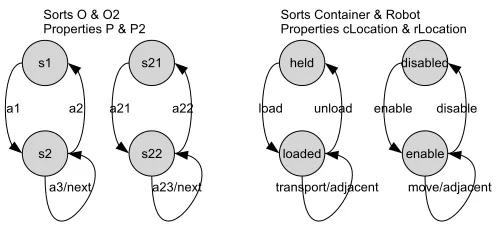
Domain definitions normally involve changes to objects drawn from different dynamic sorts, and the changes made in the life history of one object sort may be dependent on coordinating with the states and changes made to some other object sorts. We will illustrate the ways in which state machines may combine with reference to Figure 3 which introduces a second state machine for objects of sort O2. This state machine is structurally identical to that in Figure 2. Again, we also give an example drawn from the DWR domain. We describe variations on three different combinations where coordination among state machines occur.
1. Prevail requires that for an object of sort O to make a transition, some object, normally of some other sort O2, must be in a required state, and remains in that state during action execution.
2. Necessary combinations require two or more objects, normally of different sorts to make tran-sitions simultaneously.
3. Conditional combinations require one object, if in the appropriate state, to make a transition only if a second object, normally of a different sort, makes a specified transition.
2.3.1 Prevail combinations
In Figure 3(a) the actiona1 for sortOmay require that an object instance of sortO2 is in states21 and remains in that state.
This requires a parameter for an object of typeO2 to be added to the action definition and also that the predicate asserting that the object instance? O2 is in state s21 is added to the actions precondition as shown in Listing 4.
Theprevailcondition can be more complex in that the connection may set up an enduring asso-ciation between the object of sortOand the object of sortO2. This, for example, could happen in
(:action a1 (:action load
:parameters ( ?O - o, ?02 o2) :parameters (?C - container, ?R - robot) :precondition (and :precondition (and
(s1 ?O) (held ?C) (s21 ?O2) (disabled ?R)
) )
:effect (and :effect (and
(not (s1 ?O)) (not (held ?C)) (s2 ?O) (loaded ?C)
) )
) )
[image:5.595.154.405.77.193.2]Listing 4 Actions requiring a prevail combination
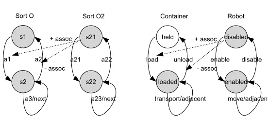
the DWR domain when a container is loaded onto a robot truck. It must be remembered onto which truck the container is loaded so that it can eventually be unloaded from the same truck. The association needs to be remembered in all the states reachable as a result of performing the action until such time that the association is explicitly ended. In the DWRexample the unload action will explicitly end the association. To capture such associations diagrammatically we can add connecting arrows suitably annotated to show the intention, as in Figure 4, and this is what is done in the object life history editor (OLHE) of GIPO. In terms of the propositional code for the resulting action a1, the association is captured by adding an extra argument to the target state of the action. In fact an extra argument will be added to all states reachable from the action and removed only when an action explicitly ends the association. In this example the state predicate for the state s2 has been modified to include an argument for a value of type O2. This definition of the state predicate replaces the old one and must be used in all references to states2 (Listing 5).
There are other features that can be present in a prevail condition. For example, the properties of the connected objects may be required to be coordinated in some way, and there may also be a need for multiple instances of object of sort O2 to be associated with the action. In the DWR example above, the properties of ‘location’ for the container and robot would be required to have the same value. How we deal with such elaborations is fully described in the GIPO manual, but essentially it involves annotating the arrows showing the connection between actions and states.
2.3.2 Necessary combinations
[image:6.595.177.453.68.190.2]A second major way in which the actions of differing object sorts may need to be coordinated is where transitions from differing sorts both refer to the same action. It may, for example, be the case that both actionsa1 anda21 are required to occur together. From the perspective of the plan-ning executive they may refer to the same action. This is easily accomplished at the propositional level where the bodies of the two distinct actions are combined into a single description and the result given a common action name (Listing 6).
Figure 4 Multi sort state machines showing prevail connection. Abstract (a)DWR(b)
(:action a1 (:action load
:parameters (?O - o, ?02 - o2) :parameters (?C - container, ?R - robot) :precondition (and :precondition (and
(s1 ?O) (held ?C) (s21 ?O2) (disabled ?R)
) )
:effect (and :effect (and (not (s1 ?O)) (not (held ?C)) (s2 ?O ?O2) (loaded ?C ?R)
) )
) )
A second example might be where the self-loop transitions a3 and a23, as in Figure 4, are required to occur together. Both have the property changing restriction that requires their declared property ‘prop’ to change value as dictated by the ‘next’ propositional restriction. In terms of the DWR example we could require that the transport and move actions occur together, and the container and robot to make the same change in location. We show such restrictions on the diagrams by using double-headed arrows connecting the specified transitions. As withprevailconditions, neces-saryconditions can be further elaborated to allow associations to be created and ended and also to allow the properties of the connected objects to be required to match in some way.
2.3.3 Conditional combinations
Conditional combinations occur where the primary transition is joined with a secondary such that the primary transition may occur without the secondary but not the secondary without the primary. If the above-described connection between a1 and a2 was a conditional combination rather than anecessarycombination, the resulting action would be as seen in Listing 7.
The conditional combination requires thateveryobject capable of making the secondary transi-tion, that is, where the precondition is met, must make the transition to the new state. The second-ary transition cannot be made if there is no accompanying object making the primsecond-ary transition. In the DWR example, the connections between the ‘transport’ action of the container and ‘move’ action of the robot are most plausibly treated as a conditional combination. The robot may move without any container being loaded, whereas the container may only be transported once loaded on a robot. The full move action (automatically generated by GIPO) with the restriction that the robot can only move to adjacent locations is shown in Listing 8.
(:action a1 (:action a21
:parameters ( ?O - o) :parameters ( ?O2 - o2) :precondition (and :precondition (and
(s1 ?O) (s21 ?O2)
) )
:effect (and :effect (and
(not (s1 ?O)) (not (s21 ?O2)) (s2 ?O) (s22 ?O2)
) )
) )
becomes
(:action a1
:parameters ( ?O - o ?O2 -o2) :precondition (and
(s1 ?O) (s21 ?O2) )
:effect (and (not (s1 ?O)) (not (s21 ?O2) (s2 ?O) (s22 ?O2) )
)
Listing 6 Action requiring necessary combinations
(:action a1
:parameters ( ?O - o) :precondition
(s1 ?O) :effect (and
(not (s1 ?O)) (s2 ?O)
(forall (?O2 - o2) (when (s21 ?O2)
(and
(not (s21 ?O2) (s22 ?O2))))) )
)
3 The GIPO environment
Our intention in creating the GIPO Environment is not simply to develop a tool for the creation of planning domains in the internal object-centric representation language, but to promote the tool as a modelling tool irrespective of the final target language. The overall architecture of the environment is shown in Figure 5. Central to GIPO is the object-centric internal representation of domains which is manipulated by all major tool elements. The environment contains a range of domain acquisition tools and associated static validation routines to promote the accuracy of the formulation. The global static validation tool can be used to report on likely faults and omis-sions in the model. Once a model appears to be acceptable the plan stepper and plan animator, with the associated internal planners, can be used to further dynamically check the model. To enable GIPO to be used as a general domain modelling tool we have developed translators between our internal language OCLh and PDDL (Simpson et al., 2000). We also provide an API to enable external planning systems to interface to the tools to provide scope for testing and fielding alternative planning algorithms to those internal to GIPO. Currently the interface allows planners which can input OCL or typed and optionally conditional PDDL. As an example, we have successfully tested the embedding of FF version 2.3 (Hoffmann, 2000) and LPG version 2.1 (Gerevini & Serina, 2002) into GIPO to allow running the planners on selected problems and viewing output in tools such as the plan animator. There is no requirement to amend any of the distributed code for third party planners: pre- and post-processing scripts take care of differences among individual systems.
3.1 Initial domain definition within GIPO
GIPO provides a range of graphical editors to enable the initial creation of domain definitions. To use the basic editors the user follows the ‘Domain Definition Methodology’ as presented in the GIPO tutorials. These basic editors closely follow the structure of domains expressed in OCL orOCLh, where the user must first name the classes of objects which can participate in the pro-blem domain. The user, in sequence, defines the predicates that are used to describe object instances, and defines object class states, which characterize the legal combinations of predicates that may be used to describe object instances. The concluding steps are to define the domain actions and HTN methods, if appropriate. Problem instances can then be defined and dynamic domain testing carried out.
The basic method of domain editing, although removing the need to have a deep understanding of the domain formulation at a textual level, has been superceded by the OLHE as described in the next subsection. A major limitation of the basic method is that it does not naturally give any guidance as to how the appropriate predicates should be chosen to describe the object types in the domain. To provide a rationale for the choice of predicates, the user needs to be provided
(:action move
:parameters ( ?R - robot ?L1 - location ?L2 - location) :precondition
(enabled ?R) (rLocation ?R ?L1) (adjacent ?L1 ?l2) :effect (and
(not (rLocation ?R ?l1)) (rLocation ?R ?L2) (forall (?C - container)
(when (and
(loaded ?C ?R) (cLocation C? ?L1)) (and
(not (cLocation ?C ?L1) (cLocation ?C ?L2))))) )
)
with a guide to the potential role that the predicates can play in the description of the objects. Creating object life histories focuses the user on such roles, rather than on the predicates required to describe them.
3.2 Object life histories in GIPO
The OLHE allows the user to draw state machines that describe the domain’s dynamic object classes. GIPO then automatically generates the domain definition from those diagrams.
In Figure 6(a) we show the state machine for thecraneas modelled in the DWR example. States are shown in rectangles with appropriate icons and state names, where as state transitions are shown as roundtangles and labelled with the name of an action that would bring about the change in state as shown by the transition arrows. The figure shows that a crane is in one of two states and that there are two different actions that can trigger state changes from either state to the other.
[image:9.595.138.417.74.435.2]In Figure 6(b) we show the robot state machine and show how we diagrammatically represent the ability of a robot to change location by driving along the dock track. The ‘moveTo’ and ‘takeTo’ transitions are property changing transitions, which are distinguished from other transitions by colour. When a robot makes one of these transitions, it will change property value — in this case the location of the robot. Viewing the property inspector in the editor (Figure 7) reveals the properties associated with the objects and any constraints placed on property changes.
Figure 5 Architectural breakdown of GIPO
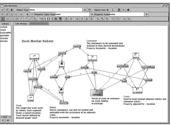
[image:9.595.156.402.80.243.2]An indication of how the connections are shown between the state machines for the different dynamic sorts is given in Figure 8, where the complete model for the DWR domain is presented.
3.3 Scaling to large domains
Using the basic OHLE, designing a large domain specification at the level of charting every object transition and all connections among them is still a complex task. We do believe, however, that the visualizations greatly expedite the task of domain definition. To assist further in providing visualizations that are easy to grasp, we provide features such as the ability to selectively view part of the emerging domain and switch on and off connections linking the differentsortstate dia-grams. More importantly, to aid both visualization and reuse, GIPO provides methods to allow some of the complexity to be encapsulated in higher order structures. Such higher order structures form ‘packages’. We need this both to simplify diagrams to allow the essential structure of the domain to be more easily envisaged, and to allow for reuse of complex but often repeated struc-tural elements. We require reuse for different object types within the same domain and across mul-tiple domains. GIPO provides mechanisms to allow domain developers to isolate diagrams which may be formulated into package structures. These provide a public interface to private substruc-tures and store these in a library for reuse. Packages are used in the completed DWR model as shown in Figure 8. In this diagram the states of the container while on a stack are encapsulated in the package ‘onStack’.
[image:10.595.226.407.82.163.2]By constructing complex state machines and showing how action transitions coordinate, com-plete domain definitions can be built up. The textual representation of the domain is generated automatically from the diagram. To produce a testable domain all the user needs do is to add Figure 7 Property inspector
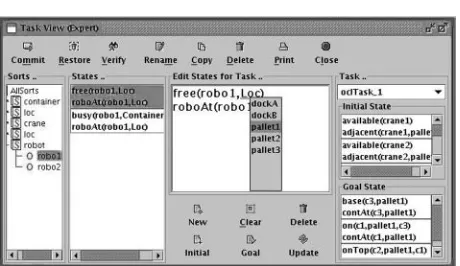
[image:10.595.170.469.197.416.2]the information to create problem instances. GIPO provides support for this in the ‘Task Editor’. The user is presented with lists of predicates defining the possible states of each object class and is allowed to select possible values to instantiate both initial and goal states for tasks. This process is shown in Figure 9.
3.4 Opmaker
To lower the threshold of prior knowledge required to develop planning domain models GIPO incorporates an action induction process, called opmaker (the reader is referred to McCluskey et al. (2002) for a more detailed description and evaluation of the tool). This tool is aimed at the knowledge engineer with good domain knowledge but weaker general knowledge of AI plan-ning.Opmakerrequires as input an initial structural description of the domain along with a well-understood training problem accompanied by an action sequence adequate to solve the training problem. In particular we assume that the modeller’s partial construction of the domain definition has reached the stage where there exists at least a class hierarchy, predicate and state definitions. This may have been done using either the basic editors of GIPO or by partially describing the domain using theOLHE.
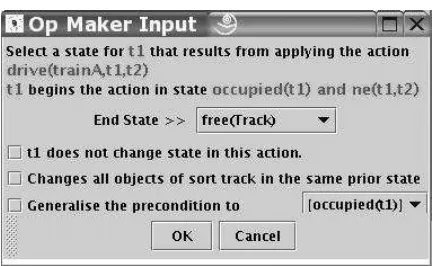
To runOpmakerthe user must specify the training problem, using the task editor (see Figure 9). A task specification defines an initial state for every object in the problem and the desired state of a subset of these objects as the goal state to be achieved. The user now suppliesopmakerwith the training sequence of actions. An action is simply the chosen name for the action followed by the names of all objects that participate in the application of the action. A good sequence of actions would ideally include instances of all actions required in the domain, though this is not required by opmaker; the action set can be built up incrementally using different problem instances. A snapshot of an element of the dialogue carried out byopmaker to help infer action structure is shown in Figure 10.
[image:11.595.164.394.74.207.2]the training sequence and may be refined in cases where the derived action only provides a partial match with the new instance. In this way opmakersteps through the training sequence, querying the user and advancing the state of each object referenced in the action schema until the training sequence is exhausted.
3.5 HTN planning
GIPO provides editors and tools to support HTN planning as expressed in the OCLhlanguage (McCluskey & Kitchin, 1998). In brief, GIPO allows the definition ofmethodswhich are actions that can be specified in terms of a composition of actions as defined for classical planning. Primi-tive actions are the non-composite actions defined in GIPO as already described.
HTN methods are defined in terms of three elements:
1. A declaration of the changes that the composite action guarantees to bring about for identified object types.
2. A definition of any precondition applying to any associated required object referenced in the guarantee.
3. A graph of subactions which if performed would bring about the guaranteed changes. This graph can contain nodes that we call ‘achieve goals’ that represent preconditions that may have to be achieved before a specific action in the subgraph can be carried out.
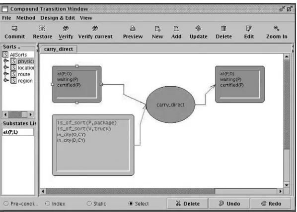
In GIPO themethodeditor allows each of these segments to be represented in a graphical form. In Figure 11 we see a method called ‘carry_direct’ being defined. This is amethodthat might be used in a logistics type domain, where packages have to be delivered by a variety of forms of transpor-tation. The top two roundtangles define the changes guaranteed when the package is transported. The guarantee requires that the package be in a state that would form a ground instance of the LHS roundtangle, namely that it is at some location Oand that it is waitingand certified. The RHS or post condition states that the package will end up at a new destination D. The bottom roundtangle expresses the precondition that the city of origin of the package and of the destina-tion be the same. The graph of acdestina-tions forming the decomposidestina-tion of the method is shown in Figure 12. Both primitive actions and other methods can be used in the definition of a decompo-sition. Method definitions may be recursive. A decomposition may include pre-conditions that apply to the actions forming the decomposition. In Figure 12 the rectangle containing the predicate at(V, O) expresses the precondition that the vehicle used to load-package must be at the same locationOas the package.
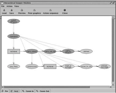
[image:12.595.209.428.77.210.2]hierarchical plan stepper. A partial snapshot of the animator in use with a logistics domain is shown in Figure 13.
3.6 Static validation
The validation of a domain definition cannot be done entirely automatically, although automated assistance in this task can be provided. Within an HTN GIPO can check that thetransparency property (McCluskeyet al., 2003) is not broken by any method definition. The transparency prop-erty gives a guarantee that if a method’s preconditions are met then the body of the method will bring about the method’s postconditions. The property is checked by performing abstract execu-tion of a method’s decomposiexecu-tion body. Warnings are then displayed to the user if a step cannot be fulfilled, given the specified preconditions of the method. In Figure 14, we see a DWR style domain where an object is to be loaded from a gripper but where the gripper cannot be guaran-teed to hold the object.
[image:13.595.130.429.79.293.2] [image:13.595.165.396.330.482.2]Within classical domains the automatic checks that GIPO can carry out tend to be at a lower syntactic level, but absence of such problems as misspelt predicate names can still save the domain developer many hours of dynamic testing. The action schema analysis tool checks the usage of each of the defined states and predicates as they are referenced in the action’s components. This Figure 12 Method decomposition
is particularly useful in conjunction withOpmaker. That a state definition is not referenced by any action would most likely indicate that the action coverage of the domain is still incomplete. Like-wise, states that are only ever referenced in the precondition, or the postcondition, act as a poten-tial indicator of incompleteness. When the OLHE is used, internal consistency checking is applied before generation of the domain definition.
3.7 Dynamic validation
[image:14.595.114.522.80.408.2]The most powerful facility that GIPO provides for dynamic validation of domains are the manual steppers. The role of the steppers is to allow the domain engineer to check that the Figure 13 Partial animation of an HTN planner’s output
[image:14.595.204.431.456.596.2]domain specification does support known plans for well-understood problems within the domain. This may be checked by running planners with the known problems, but failure to find the plan may indicate a problem or limitation of the planner, rather than the domain specification. To check the domain independently of any particular planner, the plan needs to be manually pro-duced, which is done using GIPO’s steppers. The stepper for classical planning works as a forward planner where the user selects the actions to solve the problem. As the application of each action is checked, the user can isolate the point where a domain definition fails to allow an action to be performed, where the user thinks the action should be allowed. The stepper is adept at helping the user discovering subtle bugs and their location within a domain definition. In Figure 15 a domain to test a model of multiple trains moving on a single line track is being stepped. The user is instantiating an instance of the ‘drive’ action to step through the growing plan.
For HTN domains the stepper works in a top–down left to right mode. When a user selects a method as part of a plan the decomposition of that method must be manually stepped. The HTN stepper incrementally produces a diagram with a structure identical to that produced by the HTN plan animator as shown in Figure 13.
3.8 Implementation
GIPO is largely written in Java and is hence platform independent. The integrated planners, includingHyHTN, are written in Prolog as are some of the other tools. The GIPO distribution includes Sicstus Prolog run time environments to support the Prolog subsystem. External third party planners can be run from within GIPO if they have a command line interface that allows the specification of input domain and problem files and they process classical PDDL. Planner spe-cific scripts are required to pre- and post-process the planner input and output to enable the plan-ner to be fully integrated in the system. The GIPO distribution is binary though the Java sources are also made freely available.
4 Related work
4.1 Related tool sets
[image:15.595.156.405.78.252.2]in the task of domain definition. Both systems, however, were designed to be highly coupled to their own built-in HTN planning engines. In contrast GIPO has an open API to link public domain planning engines to the system. Similar work to our own in knowledge acquisition and engineering tends to be aimed at general KBS rather than being specific to AI Planning. For example, systems such as those based on EXPECT (Blythe et al., 2001) or PROTEGE (Gennari et al., 2003) are more general purpose and do not aim at providing support to the very specific task of acquiring domain knowledge with a view to producing a formal specification as an output to be used with planning engines.
A recent tools environment called itSIMPLE (Vacquero, Tonidanel & Silva, 2005) is, like GIPO, based on an object-centric perspective and aimed at the acquisition of planning knowledge. It includes tools for the acquisition and manipulation of domain definitions, but it differs in that it adopts the widely used software system modelling language UML as its underlying philosophy. This approach may well help to make AI planning techniques more accessible by using an approach that is well known to software engineers. However, it is yet to be shown that the use of the general UML framework would be appropriate to engineer the peculiarities of planning domain definitions.
Edelkamp and Mehler’s ModPlan(Edelkamp & Mehler, 2005) is another recently developed tool which helps in planning knowledge acquisition and engineering. Their workbench includes a range of functions including static analysis, goal ordering generation and domain inference. Their work can be seem as complementary to ours, as the functions of ModPlan have the per-spective of acquiring heuristics to aid in the efficiency of AI planners. The functions of GIPO, however, are aimed less at acquiring heuristics and more at acquiring and validating domain structure.
4.2 Representational issues
The use of state machines to describe elements of planning domains is not new. State machines are used by Fox & Long (1997) in domain analysis to extract and describe useful structure from domain specifications with a view to enhance the efficiency of planning software. The novel angle of our work is to use state machines allied to the object-centric view to form a basis for the crea-tion and systematic descripcrea-tion of complete domain definicrea-tions. The work on analogical reasoning (Garagnani, 2004) bears some superficial similarities to this work, but differs in its purpose, in that it introduces a notation that is designed to be more efficient than symbolic notations. Further, Garagnani postulates a diagrammatic inter-lingua for domain definitions themselves, whereas diagrams in our work are used as an interface to help in the formulation of a symbolic definition.
GIPO’s internal representation language is based on previous work by McCluskey & Porteous (1997). The reader is referred to that reference for more information on the representation language and a further discussion of related work.
5 Conclusion and future work
In this paper we have shown how an object-centric view can assist planning domain formulation. We have also shown how that view can be used to superimpose structure and guide specification in languages such as PDDL. Environments such as O-Plan (Tateet al., 1994, 2005) and SIPE-2 (Wilkins, 1999, 2000) amply demonstrate that complex tools environments are required to enable AI planning solutions to be adopted in organizational contexts. GIPO provides much of this support when deploying the range of currently available planning systems using either PDDL or OCL.
GIPO is still under development. Its OLHE is at abetalevel of release. We are still experiment-ing with the nature of the visualization and with the editexperiment-ing mechanisms to allow the life histories to be easily produced, edited and encapsulated into reusable library structures. Although GIPO’s OLHE is being used in undergraduate teaching, a full user evaluation is still to be carried out. Two main enhancements are desirable:
1. A significant engineering challenge in AI Planning is the efficient acquisition of HTN actions. Currently, the OLHE is restricted to non-hierarchical domains. A very useful development of the OLHE would be to enable it to capture HTN actions and hierarchical domain structure in general.
2. The scope of domains capable of being modelled within GIPO needs extending, to be able to keep apace with new versions of PDDL. There is a partial implementation of PDDL level 5 in the current release, together with an updated OLHE, but with reduced tool support. For example, currently we have no planner integrated into GIPO that can generate plans in such continuous domains.
GIPO is available fromhttp://scom.hud.ac.uk/planform/gipo.
Acknowledgements
We acknowledge the help of others in the GIPO project. Many of the Prolog tools and in parti-cular the planner HyHTN were written by Donghong Lui. Weihong Zhoa contributed signifi-cantly to the creation of the the Java interface. Other members of the planning team at the University of Huddersfield have contributed intellectually to its development as did members of the Planform projecthttp://scom.hud.ac.uk/planform/.
References
Backstrom, C. and Nebel, B. 1995 Complexity results for sasþplanning.Computational Intelligence11(4), 625–656.
Blythe, J., Kim, J., Ramachandran, S., Gil, Y. 2001 An integrated environment for knowledge acquisition. Proceedings of the Interenational Conference on User Interfaces. ACM Press.
Edelkamp, S. and Mehler, T. 2005 Knowledge acquisition and knowledge engineering in theModPlan work-bench. InProceedings of the First International Competition on Knowledge Engineering for AI Planning, Monterey, California, USA.
Fikes, RE., and Nilsson, NJ. 1971 STRIPS: A new approach to the application of theorem proving to pro-blem solving.Artificial Intelligence2, 189–208.
Fox, M., and Long, D. 1997 The automatic inference of state invariants in TIM.JAIR9, 367–421. Fox, M., and Long, D. 2001 PDDL2.1: an extension to PDDL for expressing temporal planning domains. In
Technical Report, Dept of Computer Science, University of Durham.
Gennari, JH., Musen, MA., Fergerson, RW., Grosso, WE., Crubezy, M., Eriksson, H., Noy, NF. and Tu, SW. 2003 The evolution of protege: an environment for knowledge-based systems development. International Journal of Human-Computer Studies58, 89–123.
Gerevini, A. and Serina, I. 2002 LPG: a planner based on local search for planning graphs. InThe Sixth International Conference on Artificial Intelligence Planning Systems. AAAI.
Ghallab, M., Howe, A., Knoblock, C., McDermott, D., Ram, A., Veloso, M., Weld, D., and Wilkins, D. 1998 Pddl — the planning domain definition language. Technical Report CVC TR-98-003/DCS TR-1165, Yale Center for Computational Vision and Control.
Ghallab, M., Nau, D. and Traverso, P. 2004Automated Planning: Theory and Practice. CA, USA: Morgan Kaufmann ISBN 1-55860-856-7.
Hoffmann, J. 2000 A heuristic for domain independent planning and its use in an enforced hill-climbing algo-rithm. In Proceedings of the 14th Workshop on Planning and Configuration—New Results in Planning, Scheduling and Design.
Manzano, M. 1993 Introduction to many sorted logic. In Meinke, K. and Tucker, J., (ed.),Many Sorted Logic and Its Applications. New York, NY, USA: Wiley pp. 3–81.
McCluskey, TL. and Kitchin, DE. 1998 A tool-supported approach to engineering HTN planning models. In Proceedings of 10th IEEE International Conference on Tools with Artificial Intelligence. IEEE Press. McCluskey, TL. and Porteous, JM. 1997 Engineering and compiling planning domain models to promote
validity and efficiency.Artificial Intelligence95, 1–65.
McCluskey, TL. and Simpson, RM. 2005 The use of an integrated tool to support teaching and learning in artificial intelligence. Journal of Innovations in Teaching And Learning in Information and Computer Sciences: Special Issue on Teaching Artificial Intelligence and Intelligent Agents: Challenges and Perspectives4(3).
McCluskey, TL., Kitchin, DE., and Porteous, JM. 1996 Object-centred planning: lifting classical planning from the literal level to the object level. InProceedings of 8th IEEE International Conference on Tools with Artificial Intelligence. IEEE Press.
McCluskey, TL., Richardson, NE. and Simpson, RM. 2002 An interactive method for inducing operator descriptions. InThe 6th International Conference on Artificial Intelligence Planning and Scheduling. AAAI. McCluskey, TL., Liu, D. and Simpson, RM. 2003 GIPO II: HTN planning in a tool-supported knowledge engineering environment. InThe 13th International Conference on Automated Planning and Scheduling. AAAI.
Nau, D., Cao, Y., Lotem, A. and Munoz-Avila, H. 1999 SHOP: simple hierarchical ordered planner. In Proceedings of the 16th International Joint Conference on Artificial Intelligence. CA, USA: Morgan Kaufmann.
Nebel, B. 2000 On the compilability and expressive power of propositional planning formalisms.Journal of Artificial Intelligence Research12, 271–315.
Simpson, RM., McCluskey, TL., Liu, D. and Kitchin, DE. 2000 Knowledge representation in planning: A PDDL to OCLhtranslation. In Proceedings of the 12th International Symposium on Methodologies for Intelligent Systems. London: Springer Verlag.
Tate, A., Drabble, B. and Kirby, R. 1994 O-Plan2: an open architecture for command, planning and control. In Fox, M. and Zweben, M., (ed).Intelligent Scheduling. Palo Alto, CA, USA: Morgan Kaufmann. Tate, A., Dalton, J., Levine, J., Polyak, S. and Wickler, G. 2005 O-plan - open planning architecture.
http://www.aiai.ed.ac.uk/oplan.
Vacquero, TS., Tonidanel, F. and Silva, JR. 2005 The itSIMPLE tool for modelling planning domains. In Proceedings of the First International Competition on Knowledge Engineering for AI Planning, Monterey, California, USA.
Wilkins, D. 1999 Using the SIPE-2 planning system: a manual for SIPE-2, version5.0. SRI International, Artificial Intelligence Center.