Effect of Communication Range with Node
Cooperation in Wireless Passive Sensor Networks
1
Farman Ullah,
2Aamir
Khan
1,2
COMSATS Insititute of IT Quaid Avenue, Wah Cantt.
Pujnab, Pakistan
Imdad Ullah
SEECS, NUST, Islamabad, Pakistan
Hasan Farooq
Universiti Tecknologi Petronas, Malaysia
ABSTRACT
Node cooperation is considered in this paper in the existence of two relaying protocols i.e. “Amplify and Forward (AF)” also called “Store and Forward (SF)” and the second relaying protocol is “Decode and Forward”. The two stated protocols are different from each other and perform different operations on received data before retransmitting to next hop. Also the selection of each protocol is varying in accordance to the dis-tance of a sensor node from the destination node (RF source). It is suggested in this literature that a relay node close to the source node will employ Decode and Forward and if it is close to the destination node, then Amplify and Forward will be employed. This work is achieved by first modelling an empirical system consists of single relay, source and destina-tion. And the two relaying protocols (SF and DF) were modelled and implemented. This approach is then extended for three relay nodes and the two sets of relaying nodes were implemented again on every single node and then the output performances were compared. Finally using analytical ap-proach, the communication range or the capacity of RF source to charge the sensor nodes in certain area was also evaluated and it is considered that the relay nodes within the prescribed range are successfully charged in charging stage. And in communication stage, the relay node was allowed to keep at various distances from the source node and evaluate the per-formance of each relaying protocol on a particular distance from source and destination.
1.
INTRODUCTION
In wireless sensor networks, signal is severely degraded by the multipath signals which can be compensated with the use of diversity. Taking the advantageous of diversity, the destina-tion node accumulates or combines all the received signals received via independent links and makes the final decision upon the transmitted bits. This characteristic of sensor net-works is called the cooperative attempt and is always there when they are active. Sensor nodes, with this property en-hance their quality of service and offer good BER compare to the conventional mode of communication. The senor nodes make use of their processing capabilities to locally carry out simple calculations and send out only interested data [5]. This approach or capability of WPSN can offer spatial diversity against fading in a wireless channel [22]-[23]. If there is no direct line of sight or having difficulty in communication, then one sensor node help another, called relay node in order to accomplish transmission from source to the desired destina-tion [23]. This cooperative behaviour is adopted by each sensor node in the network along with the normal communi-cation responsibility.
Node Cooperation results in various trades off in terms of resources e.g. data rate and transmit power. Because in coop-erative mode if there are “N” number of sensor nodes, then the total power would be divided into “N” number of portions and with that individual part of the total power, the data would be transmitted to each node. Hence, total power available at the single node divided and thus it is reduced for all users because of diversity [24].
The scenario that this work will consider would assume that all nodes work in the same band and therefore the source node will behave in broadcast manner, while the destination node is in multiple channel access mode as depicted in the following figure 1. Channel between each pair of node is in-dependent and have random effect on data.
Broadcast Multi Access Channel 1
Channel 2
Channel 3 Source Node
Relay Node
Destination Node
Figure 1: A 2 hops relaying system
1.1. Relaying Protocols
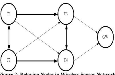
Figure 2: Relaying Nodes in Wireless Sensor Network
Each transmitting terminal focuses to send the data to their respective destination e.g. in a direct transmission be-tween T1 and T3, the node T1 acts as source and T2 acts as relay node. So that in the case when fading is severe between T1 and T3 and transmission is not successful, then informa-tion is sent through the relay node (T2).
Relay transmission also happens when received informa-tion is severely corrupted that is called physically degraded relay channel e.g. the destination node receives data which is very different than the one received by relay node, and then the automatic retransmission occurs through the neighbour node. It is therefore, relay channel must be coping with the following three approaches [25],[27],[28].
Facilitation
• Relay should keep the interference smaller as much possible between the active communicating nodes to let them to transfer data more reliably.
• Relay must not help the source directly.
Cooperation
• Since resources are shared with T2 as well, there-fore it fully decodes the source message and retransmits the source message in case T1 fails to deliver data successfully to destination node. Also in certain scenario, the received signal is not neces-sarily decoded, but simply reshape that signal to a higher amplitude and transmit towards the destina-tion
Observation
• Relay encodes the quantized version of received signal and keeps record of every transmission that has been sent towards the destination.
In node cooperation, various protocols are employed to perform various operations. In fixed relaying, the received signal is either Amplify-and-Forward or Decode-and-Forward, depends upon the power availability.
Cooperative behaviour of sensor nodes created new ap-proaches to enhance the sensor lifetime, low cost and multi functional operation in the sensor field. This approach created spatial diversity against fading in a wireless channel. In the case of sever fading channel, the source node is assisted by the relay channel to reach the information to the destination. This is basically done by the node relaying protocol called AF and DF. If the received signal SNR is below the threshold, due to which transmission is made unsuccessful, therefore message is encoded, re-encoded and retransmitted towards the destination. This decision is taken by the relay node on the single bit feedback, broadcasted by the destination that is at least reliably received by the relay node. Information is either corrupted by Reflection, Scattering or Diffraction etc or due to the Small Scale Fading effect of the channel.
2.
SYSTEM MODEL AND ACHIEVED
RESULTS WITH DISCUSSION
When signal is transmitted over a long communication path, the received signal is observed in a different form than the original. The envelope amplitude of this signal when observed would seem to be fluctuating as the time passes by. This effect is caused by “fading”. This effect puts some limitations on the system design. However, if different signals are received, then fading over one path is different than another [34],[35]. Therefore if copy of the same signal is received via different links, then it is rarely happen that all channels are severely faded but it is good for reducing fading effect. This technique is called “diversity” which improves the combined signal to noise ratio and process of combining these signals at the re-ceiver is called “Maximal Ratio Diversity” or Maximum Ration Combining (MRC) [36],[37].
2.1. System Design
[image:2.595.66.269.67.199.2]Data passed through each relay node would be passed through the process shown by the following block diagram but only if the serving relay is choosing DF mode for retrans-mission of the received signal.
Figure 31: Block diagram of a Digital Communication Process System
Data Source
Encoder
Modulator
Channel
De Modulator
Block diagram shows that initially, the data source randomly generates bit stream of 0s and 1s. Data stream is passed through encoder. Half convolutional encoder would be used in system design, which will introduce redundant bits equal to the information bits i.e. each information bit would have one redundant bit. The encoded bits would be modulated using different modulation schemes e.g. BPSK, QPSK etc. The modulator would generate a set of finite time duration wave-forms and will provide mapping between the encoder output and the generated set of waveforms. The modulated signal is passed through flat fade channel and channel state information is known at the receiver. Channel introduces multiplicative noise but at the receiver, the received signal is also distorted by the AWGN noise. At the receiver, the same modulation scheme is used to de-map the signal and user data is decoded from the de-mapped signal.
The above block diagram would be integrated in each re-lay which could be more generally seen in the form of following flow chart.
S
R1
D
Cha nnel
2, N oise
2
Ch annel3
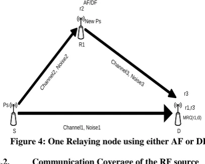
, N oise3 r1,r3 MRC(r1,r3) r2 Ps New Ps Channel1, Noise1 r3 AF/DF
Figure 4: One Relaying node using either AF or DF
2.2. Communication Coverage of the RF source
This section will calculate range or communication cover-age of RF source. So the sensor nodes coming within the calculated range would be successfully charged.
In order to do this, the battery free sensor node (P2110) is considered. P2110 converts the received RF energy into DC, which is stored in capacitor. The capacitor is constantly charged unless the charging threshold is obtained. Soon as the threshold level achieved, the output voltage is enabled and device starts functioning. Similarly when charging level drops below the threshold level, the output voltage is turned off [21]. Typical voltage on sensor node is 1.24V according to [31]. Based on this value, power received by the RF source could be worked out by recalling equation of received power.
)
(
8
2 L t t rR
R
V
P
(1)P2110 can best perform in the range of 902-928MHz (typical-ly 915MHz) with RF and sensor node impedances of 50 ohms. Substituting
1
.
24
r50
l50
t
V
R
R
V
in equation 1} 30 { 8 . 2 ) ( 27 ) ( 92 . 1 ) 50 50 ( 8 ) 24 . 1 ( ) ( 8 |
| 2 2
XdBm XdBW dBm dB P dBW dB P mW P R R V P r r r l r t r ....(2)
The calculated Pr is the minimum power by which the sensor
could be activated. This power would at least cross the threshold level of the sensor and would let the sensor to start functioning.
Typical EIRP used by the RF source is 4W to power the sensor node with 6dBi transmit antenna gain. The received antenna gain is proposed as 4dBi [40].
dBi G dBi G dBm dB P dBW dB P W P t r t t t 6 4 02 . 36 ) ( 02 . 6 ) ( 4
m
MHz
s
m
323
.
0
915
/
10
*
3
8
...(3)Substituting the above parameters in Friis transmission equation
r t rf t
r
G
G
R
P
P
)
24
(
323 . 0 10 * 14 . 3 * 4 1 ) * 14 . 3 * 4 323 . 0 log( 20 4 6 02 . 36 8 . 2 ) 4 log( 20 ) 20 10 02 . 36 8 . 2 ( , , , r t r t r t r t t r R R R G G P P
m
R
t,r
3
.
72
(4)Equation 4 shows that, the sensors within the radius of 3.72m would be successfully charged. Also it can be said that the sensor node would only have 2.8dBm power to utilize and to distribute among the neighbour sensor nodes over the ra-dius of 3.72m.
This range could be increased or decreased i.e. it could be set to the desired value by taking one of the following resistor values.
Received voltage at the sensor node could also be in-creased or dein-creased by connecting the resistor of values
according to out out
V
V
k
R
32
.
3
)
195
.
1
(
249
and
32 . 3 47 . 297 out V K R
[image:3.595.58.262.272.435.2]Now by keeping source node at a fixed position i.e. 3.72m and let this node to transmit data with power what it can have from the RF source at this point. The relay node performance could be demonstrated at various distances with respect to the fixed source node as could be seen from figure 5.
In above figure, the relay node is kept at various distances in order to see the performances. In this case, it could be said (in simplest form) that as sensor node approach towards the RF source, the sensor node receives more and more power in the same unit of time, because for the same charging time dura-tion and equal size plate of the inside capacitor would be more quickly charged at distance close to the RF source compare to the one kept farther from the RF source.
The source node transmits with constant power and as the relay node retransmits the received data with always larger power than the source power. Following distances were fixed for this experiment and received power is evaluated at each new distance as shown in the following table. Received power is evaluated using Friis Transmission equation.
S.No Distance Relay’s Received
Power
1 3.3067 5.8393
2 3.2550 5.9914
3 3.1886 6.1829
4 3.1000 6.4316
5 2.9760 6.7684
6 2.7900 7.2527
7 1.8600 9.4616
8 0.9300 11.7186
9 0.6200 12.6426
10 0.4650 13.1963
11 0.3720 13.5819
[image:4.595.334.505.74.204.2]12 0.3100 13.8734
Table 1: Received power by the sensor node at various distances
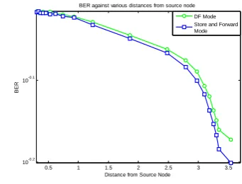
It is obvious from table 1, as the sensor node approaching towards the destination node, the received power at each point is constantly increasing. With this power, the sensor node will retransmit the received data. Each time the relay node re-transmits the received data with higher power as approaching towards the destination node, the results of which could be seen from figure 6.
6 8 10 12 14 16 18 20 22 24 10-0.19
10-0.16 10-0.13 10-0.1 10-0.07 10-0.04
SNR(dB)
BER
Relay performance at various distances from data source node DF Mode AF Mode
Figure 6 Relay outputs at various received power (ob-tained at various distances) with respect to the source
node.
0.5 1 1.5 2 2.5 3 3.5
10-0.2 10-0.1
Distance from Source Node
BER
BER against various distances from source node
DF Mode Store and Forward Mode
Figure7. Relay outputs at various distances with respect to the data source node
3.
CONCLUSION
It has been considered that relay is fixed in the middle of source and destination link and plot BER against the SNR. At this point, when source node transmits the generated data with half the available power, the use of two relaying protocols proves that AF gives good performance compared to DF and Conventional mode of transmissions. As a result of the out-puts, it could be added that if the received data is demodulated from carrier and decoded to get the original bits from the re-ceived data, then there is high chance that the final message would be highly modified and would be deviated from the source message.
4.
REFERENCES
[1] Jennifer Yick, Biswanath Mukherjee, Dipak Ghosal, “Wireless Sensor Network Survey,” J.Yick et al./ Com-puter Networks 52 (2008), pp.2292-2330, April 2008. [2] X,-Y. Li; “Multicast Capacity of Wireless Ad Hoc
Net-works”, IEEE/ACM Transaction on Networking, vol.7, no.13, pp.950-961, June2009.
[3] G,-K. Chang, Z. Jia, J. Yu. A. Chowdhury, T. Wang, G. Ellinas, “Super-Broadband Optical Wireless Access Technologies,” OFC/NFOEC 2008.
[4] A. Bereketli and O. B. Akan, “Communication Coverage in Wireless Passive Sensor Networks,” IEEE Comm. Letters, vol. 13, no. 2, pp. 133-135, Feb. 2009.
[5] I.F.Akyildiz, W.Su, Y.Sankarasubramaniam, E. Cayirci, “Wireless Sensor Networks: A Survey ” Computer Networks 38 (2002), pp.393-422, Dec 2001.
[6] Alexander Becher, Zinaida Benenson, and Maximillian Dornseif, “Tampering with Motes: Real-World Physical Attacks on Wireless Sensor Networks,” pp. 1-15.
[7] Adrian Perrig, John Stankovic, David Wagner, “Security in wireless sensor networks,” Commun. ACM, 47(6), pp.53-57, 2004.
[8] Elaine Shi and Adrian Perrig, “Designing secure sensor networks,” IEEE Wireless Communications, 11(6), pp.38-43, December 2004.
[image:4.595.49.287.224.381.2][10] D. Sakamoto and H. Higaki “Wireless Multihop Transmission with Buffering in Neighbour Sensor Nodes for Short Delay,” IEEE Communications Society, WCNC 2009.
[11] Shi Yongjie, Sun Guiling, Liu Bo. Li Weixiang, “Design of Wireless Sensor Network Node Based on C8051F020 and CC1100 Fiber Bragg Grating,” IEEE, pp. 1-4.July 2010.
[12] C. Intanagonwiwat, R. Govindan, and D. Estrin, “Directed Diffusion: A Scalable and Robus Communication Paradigm for Sensor Networks,” Proc. ACM MobiCom ’OO, Boston, MA, 2000, pp. 56-57. [13] H. Stockman, “Communication by means of Reflected
Power,” Proc. I.R.E., vol. 36, 1948, pp.1196-1204.
[14] M. Kossel, H. R. Benedickter, R. Peter, Batchtold, “Microwave Backscatter Modulation Systems,” in IEEE MIT-S Digest 2000, pp.1427-1430.
[15] C.Turner, “Backscatter modulation of Impedance Modulated RFID tags,” pp. 1-5, Feb 2003.
[16] M. Talha Isik Ozgur B. Akan, “Padre: Modulated Backscattering-based Passive Data Retrieval in Wireless Sensor Networks,” IEEE Comm So, WCN 2009 Proc,.
[17] F. Kocer, P.M. Walsh, and M. P. Flynn. “Wireless Remotely Powered Telemetry in 0.25m CMOS,” Proc, IEEE RFIC, June 2004, pp. 339-342.
[18] Yanqiu Li, Hongyun Yu, Bo Su, and Yonghong Shang, “Hybrid Micropower Source for Wireless Sensor Network,” IEEE Sensors Journal, Vol 8, N0.6, June 2008, pp. 678-681.
[19] A. K. Marath, Y. W. M. Chia, C. C. Ko, “Performance Analysis of a Homodyne Receiver in Modulated Backscattered System for Intelligent Transportation.” IEEE 1999, pp. 1198-1202.
[20] K. Han, Y. Choi, S. Choi, and Y. Kwon, “Power Amplifier Characteristic aware energy efficient Transmission Strategy,” LNCS, vol.4479, pp. 37-48, Springer, Nov.2007.
[21] Product Datasheet “P2110-915MHz RF Powerharvester Receiver,” PowerCast, Rev A-2010/04, pp.1-12.
[22] M. R. Souryal, B. R. Vojcic, “Performance of Amplify-and-Forward and Decode-Amplify-and-Forward Relaying in Rayleigh Fading with turbo codes,”IEEE ICASSP, pp.IV-68-IV-684, 2006.
[23] J. Lee, S. Kim, H. S. T. Kwon, Y. Choi, J. S and A. Par, “Downlink Node Cooperation with Node Selection Diversity,” IEEE, 2005.
[24] N. Laneman, D. N. C. Tse, G. W. Wornell, “Cooperative Diversity in Wireless Networks Efficient Protocols and Outage Behavior,” IEEE Trans: on infor theory, vol,50, No, 12, pp. 2062-3080, 12 Dec 2004.
[25] A. Nosratinia, T. E. Hunter, A. Hedayat, “Cooperative Communication Wireless Networks,” Adaptive Antennas and Mimo Systems for Wireless Comm, IEEE Comm: Magazine, pp. 74-80, Oct 2004.
[26] N. Laneman, D. N. C. Tse, G. W. Wornell, “Cooperative Diversity in Wireless Networks Efficient Protocols and Outage Behavior,” IEEE Trans: on infor theory, vol,50, No, 12, pp. 2062-3080, 12 Dec 2004.
[27] J. G. Proakis, Digital Communication, 4th ed. New York: Mc Graw-Hill, Inc., 2001.
[28] T. M. Cover and A. A. El Gamal, “Capacity theorems for the relay channel,” IEEE Trans. Infor, Theory, vol. IT-25, pp.572-584, Sept.1979.
[29] M. Yu and J. Li, “Is amplify-and-forward practically better than decode-and-forward or vice versa?”, Proc. IEEE Int. Conf. Acoustics, Speech, and Signal Processing (ICASSP). Vol. 3, pp.365-368. March 2005. [30] M-S. Alouini, A. Goldsmith, “Capacity of Rayleigh
Fading Channels Under Different Adaptive Transmission and Diversity-Combining Techniques,” IEEE Trans: on Vehicular Tech:, Vol:48, No. 4, pp. 1165-1181, July 1999. [31] T. Sunaga, S. Sampei, “Performance of multi-level QAM with post-detection maximal ration combining space diversity of digital land-mobile radio communications,” IEEE Trans: Vehicular Technology,Vol. 42, pp.294-301, Aug 1993.
[32] J. N. Laneman, “Cooperative Diversity in Wireless Networks: Algorithms and Architectures,” Ph.D. dissertation, Massachusetts Institute of Technology, Cambridge, MA, Aug. 2002.
[33] X. Bao, J. LI, “Efficient Message Relaying for Wireless User Cooperation: Decode-Amplify-Forward (DAF) and Hybrid DAF and Coded-Cooperation,” IEEE Trans: on Wireless Comm:, Vol. 6, pp. 3975-3985, Nov. 2007. [34] T. Q. Duong, H-J. Zepernick, “Hybrid
Decode-Amplify-Forward Cooperative Communications with Multiple Relays,” IEEE Comm: Soc: WCN 2009 Proc:, pp. 1-6
[35] C. R. C. M. Da Silva, M.D Yacoub, “A Generalized Solution for Diversity Combining Techniques in Fading Channels,” IEEE Trans: on Microwave Theory and Techniques, Vol. 50, No.1, pp. 46-50, Jan 2002.
[36] B.S. Paul, R. Bhattacharjee, “Maximal ratio combining of two amplify-forward relay branches with individual l inks experiencing Nakagami fading,” IEEE, pp.1-4, 2007.
[37] A. Sendonaris, E. Erkip, B. Aazhang, “User Cooperation diversity-part-1: system description,” IEEE Transactions on Comm:. Vol. 51, no.11, Nov 2003.
[38] A. Sendonaris, E. Erkip, B. Aazhang, “User Cooperation diversity-part-II: Implementation aspects and performance analysis,” IEEE Transactions on Comm:, vol.51, no.11, Nov 2003
[39] Product Datasheet “P2110-915MHz RF Powerharvester Receiver,” PowerCast, Rev A-2010/04, pp.1-12.
[40] http://www.rfwirelesssensors.com/2010/04/powercast-p2110-battery-free-wireless-sensor-node-2010-04-30/