Application of Genetic Algorithm for Tuning of
Reduced Ordered Robust PID Controller
and Computer Simulations
Muhammad Ejaz
Department of ElectronicsEngg, Faculty of Engineering, International Islamic University
Islamabad, Pakistan
ABSTRACT
Robust controllers designed via H∞ Loop Shaping are
complicated and are of order higher than that of the plant. It is very difficult to implement these controllers in practical engineering applications. To overcome this problem, Genetic Algorithm is used to approximate a robust PID controller from H∞ Loop Shaping controller so that the difficulties in
implementation of higher order controller can be avoided.
General Terms
Application of Genetic Algorithm in Robust Control System.
Keywords
Robust controller, H∞ Loop Shaping, Weight selection,
Genetic Algorithm, PID Controller and Missile control system.
1.
INTRODUCTION
H∞ Loop Shaping controller design method is a frequency domain technique to design robust controllers for the system which have uncertainty in their parameters and disturbance interferences. While designing robust controller not only robust stability is sufficient for designing control system, but also the other performances specifications of the closed loop controlled system such as rise time, settling time, overshoot and steady state error, etc. are also important considerations to be satisfied. Loop Shaping is a graphical technique for designing a controller to achieve robust stability and performance for a stable and minimum phase systems. In this approach, designer plots the singular value plot of open loop plant and carries out its analysis with view to its stability and performance specification and then accordingly designs pre and or post compensator to be used as weighting function to get desired shape of open loop plot curve of the system. In this way loop shaping approach is closely related to H
control design method in which the designer tries to minimize the maximum singular value of the plant. By shaping the plants loop function, H loop-shaping methods actually
minimize peak of maximum singular i.e. H norm of the closed loop system‟s sensitivity and complimentary sensitivity function [1].
In H∞ Loop Shaping design method first the designer selects
the suitable weights i.e. pre and or post compensator by utilizing the classical method of loop shaping satisfying good performance and stability specifications and then H∞ robust
controller is designed using H∞ Loop Shaping design method
to deal with both robust stability and robust performance specifications for control system [2]. In this method resulting controllers are of order higher than that of the original plant. So many difficulties arise when these higher order controllers
are implemented in practical engineering applications due to their hardware implementation [3]. Therefore controllers with lower orders are preferable in terms of computing efforts and being cost effective.
In this paper, Genetic Algorithm based technique is used for tuning of fix-order and fix structure PID controller from complicated and higher order H∞ Loop Shaping controller so
that the difficulties arising in implementation of higher order controller can be avoided. This method is easy to use and the resulting PID controller has given good results in both time and frequency domains as shown in computer simulations.
1.1
Previous work related to low order
control design
H PID controller has been designed for plants like Pneumatic Servo-system using Genetic Algorithm in reference [4] and Genetic Algorithm based PI controller for Boiler system is designed in reference [5]. New sufficient LMI conditions for low order controller design were presented in reference [6]; however some degree of conservatism was introduced due to the conditions only being sufficient. An algorithm that combines a randomization algorithm with a coordinate descent cross-decomposition algorithm is presented in reference [7]. Particle Swarm Optimization (PSO) has been applied to design the fixed-structure robust H∞ loop shaping controller in reference [8].
1.2
Motivation For H
PID Controller
PID controllers are extensively used in industries due to their simplicity in tuning and ease of implementation. Their easy method of tuning and simple structure leads to quick designs [9]. That is why these are most popular and commonly used fixed-structure and fixed-order controllers. These advantages make PID controllers an attractive option. A completely different approach worth mentioning is to compute the full order H∞ controller and then apply model reduction
techniques using Genetic Algorithm to get a low order controller. In this way it is possible to design a lower order fixed-order, fixed-structure and at the same time optimal and robust controller.
2.
H
LOOP SHAPING
A robust controller design technique, so called H∞ Loop
shaping methods was first introduced by Macfarlane and Glover [10]. H∞ loop-shaping design procedure provides a
disturbance rejection in low frequency region. Then designer constructs post-compensator W2 for noise suppression and
robust stability to model uncertainties in high frequency range. After shaping open loop transfer function in both low and high frequency regions, the H∞ norm of the transfer function matrix from the desired outputs Z1 & Z2to input
disturbance „w’ is minimized over all stabilizing controllers K to obtain a desired value of (i.e. cost function) as shown in Figure-2. Cost function can take value from 1 to 10.Final controller K(s) will be having the structure as shown in Figure-1.
K
(
s
)
W
1(
s
)
K
W
2(
s
)
(1)Gs
W1 G W1
W1
K∞ W1
G
[image:2.595.68.268.613.733.2]Figure-1 Loop Shaping with W1 and W2
Now factorizing the shaped plant Gs
1
)
(
)
(
N
s
M
s
G
s (2)Here N(s) and M(s) are normalized co-prime factor of the plant Gs and representing co-prime uncertainty as:-
M
M
s
M
N
N
s
N
)
(
)
(
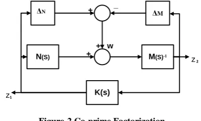
(3)Where ∆N and ∆M are uncertainty added to the plant as shown in Figure-2.
K(s)
N(S) M(S)-1
ΔN + ΔM
_
w
z1
z 2
+ +
Figure-2 Co-prime Factorization
From Figure-2 the transfer function between outputs Z1 & Z2
and input „w’ is calculated as under:-
w
s
M
K
G
I
s
M
K
G
I
K
Z
Z
w
s
M
K
G
I
K
Z
KZ
Z
w
s
M
K
G
I
Z
Z
s
N
s
M
w
s
M
Z
s s s s
1 1 1 1 2 1 1 1 1 2 1 1 1 2 2 1 1 2)
(
)
(
)
(
)
(
)
(
)
(
)
(
)
(
)
(
)
(
)
(
)
(
(4)The transfer function from outputs Z1 and Z2 to input „w’ is
calculated as:-
w
Z
Z
T
Tzw
2 2
1 1)
(
)
(
I
G
K
M
s
I
K
T
zw s (5)Here Gs is the shaped plant including W1 a pre-compensator
and W2 a post-compensator and K is the controller. Robust
stability margin
is the inverse of cost function „‟. The robust stability margin,
can only take values from zero to unity. Achieved value of robust stability margin
is an indicator of the success of the design procedure which means that compensated system will be both satisfying robust stability and robust performance at the same time. If the value of robust stability margin
is smaller than 0.2, it means that desired loop shape and the robust stability requirements cannot be achieved simultaneously. In this case the designer re-shapes the plant by re-designing the pre and or post compensators for open loop plant via trial and error procedure. The uncertainty model used in H loop shaping isthe co-prime factor uncertainty. It does not require a specific knowledge about the uncertainty. It captures both low and high frequency uncertainties. Furthermore, the real and the nominal plant model do not have to have the same number of right half plane (RHP) poles and zeros [11].
3.
GENETIC ALGORITHMS
Genetic Algorithms (GA‟s) are a global search engines and optimization tools that represent the process of natural evolution [12]. The genetic algorithm starts search with very less or even no knowledge of the exact solution and search totally depends upon responses from its environment and evolution operators i.e. reproduction, crossover and mutation which are used in objective function to arrive at the best available possible solution. GA starts at several independent objectives and searching at a time, to discard local minimum and obtaining an optimal or sub optimal solution. GA‟s are very much capable of finding out and locating high performance solutions in difficult areas without any difficulty as compared to the methods that rely on available information. GA‟s are effective at finding high performance solutions and it was decided to create an objective function that selects the optimal values of PID gains constants i.e. Kp, Kd and Ki based
compared with reference step input and minimized up to optimal value.
A traditional fix-order and fixed structure PID controller was approximated using Genetic Algorithm from H∞ Loop
Shaping controller for Missile system. Due to the different PID control laws, it was decided to specify a minimum set of attributes which in this paper are as follows:-
a. One-degree of freedom controllers is tuned.
b. The structure and order of PID controller was assumed to be of non interacting form as defined below:-
s
K
s
K
K
G
i dp
p
(6)Where Kp, Ki and Kd are proportional, integral and derivative
gains. In this way, step response of the closed loop system was plotted and error between the reference step input and desired output is denoted as:-
)
(
)
(
)
(
t
r
t
y
t
e
Error
(7)Then it is multiplied with time and integrated over whole time period. This type of Integral is called Time Multiplied Absolute Error (ITAE) criteria and is used to find out the controller parameters of equation (6):-
dt
t
e
t
ITAE
T
0)
(
ITAE
t
r
t
y
t
dt
T
0)
(
)
(
(8)Where t=time, r(t) = reference input and y(t) = measured output variable.
The Genetic Algorithm performs search on a coding of the PID controller parameters i.e. Kp, Ki and Kdto be optimized
rather than the PID gains themselves [12]. A genetic algorithm has been constructed to find out the PID parameters of the missile system. A number of objective functions were formed in order to find out the PID values chosen by the Genetic Algorithm. The objective functions were written basing on steady state error minimization criterion. Each objective function is basically the same, except for the section of code that defines the specific error performance criterion being implemented. To optimize the performance specifications of a PID feedback controlled system, the PID parameters of the system are adjusted to maximize or minimize a certain performance specification index.
4.
DESIGN EXAMPLE - MISSILE
SYSTEM
This example is taken from reference which provides the non-linear aerodynamics for single plane motion of a missile. This model gives a tail-controlled missile traveling between Mach 2 and Mach 4, at altitudes ranging from 3050 meters (10000 feet) to 18290 meters (60000 feet), and with typical angles of attack in the range of ±20 degrees [13][14]. The transfer function of the Missile Airframe is as follows: -
1.2296
s
60.6342
296.6199s
30.0638s
s
21.5795
293.1627s
-194.6598s
-)
(
4 3 22
s
G
(9)
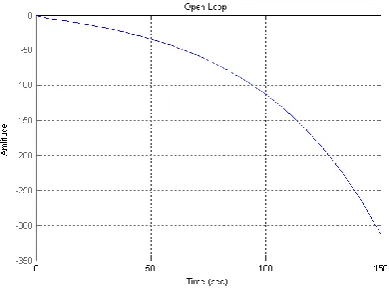
The Step Response and Singular Value (SV) plot of open loop plant without a compensator are shown in Figure-3 and Figure-4 respectively, which show that the plant is highly unstable.
Figure -3 Step Response of Open loop Plant
Figure -4 SV of Open loop Plant
The pre and post compensators for H loop shaping are
selected by using classical loop shaping method satisfying the following specifications:-
a. High gain is required in low-frequency region which is necessary for good tracking.
b. The slope of curve in low frequency range is required to be around 20 db per decade.
c. Gentle slope is required around crossover frequency. d. Slope of around 40db per decade is required in high
frequency region beyond crossover which is necessary for good noise rejection.
e. Robust Stability Margin must be 0.25<
< 0.9. [image:3.595.331.526.187.331.2]transfer functions of pre and post compensators were selected as under:-
s
s
w
1
10
(10)5
3
2
s
s
w
(11)H design method basically involves minimization of H
norm that is the peak of maximum singular value of transfer function between output and input. The Mu (µ) Analysis and Synthesis MATLAB Toolbox provide easy access to these methods [15]. The H compensator is the H stabilizing
controller, and is found using µ Analysis and Synthesis MATLAB Toolbox. The structured singular value µ is a very powerful tool for synthesis and analysis for robust controller. The structured singular value µ is a function which provides a generalization of the singular value and spectral radius. The structured singular value µ gives a compensator, which maximizes robust stability to so-called normalized coprime factor uncertainty. In this type of uncertainty, the nominal plant is given in the coprime factor form as given in equation (3). The robust design objective is not only to stabilize the nominal model but also to stabilize all the possible plants included in the family of the perturbed plants. In the co-prime perturbation form, the number of unstable poles for the perturbed form can be different than the number of unstable poles of the nominal plant.
The normalized co-prime factor uncertainty has close relationships with the type of uncertainty captured by gain and phase margins for single loop feedback systems, for example requiring gain margin of ±6 dB, and phase margin of 450 can be shown to be achieved if the coprime factor robustness measure is greater than 0.34. In feedback control systems the gain and phase margins cannot be very reliable indicators of robustness, whereas the co-prime factor uncertainty is so [9][11]. The transfer function of so designed His as under:-
.112
s
1.578
1.735s
.548s
.049s
s
.001
.072
1.031s
1.29s
.494s
.042s
.001s
2 3
4 5
2 3 4 5
H
(12)
It is evident from transfer function of H controller so designed is of 5th order which off course is of higher order than original plant and difficult to implement so a low order PID controller is approximated from this high order controller using GA. Singular Value (SV) plot of shaped plant with H are shown in Figures-5 andStep Response with HController
is shown in Figures-6.
10-4 10-3 10-2 10-1 100 101 102 103 -100
-50 0 50 100 150
SV Plot of Shaped Plant
Frequency (radians/s) (rad/sec)
M
a
g
n
itu
d
e
(
d
B
)
Figure -5 SV with H Controller
0 0.1 0.2 0.3 0.4 0.5 0.6 0.7 0.8 0.9 1 0
0.2 0.4 0.6 0.8 1 1.2 1.4
Step Response H-inf Loop-Shaping
time (seconds)
a
c
c
e
le
ra
ti
o
n
Figure -6 Step Response with H Controller
Looking at the graph of plant after H∞ loop shaping from
Figures-5 it is quite evident that the low frequency gain is high enough, which is required for good tracking, crossover slope and frequency are satisfactory and the slope beyond crossover is high enough which is required for good noise suppression and the good Robust Stability Margin (i.e. emax=.55). Figure-6 shows the time response achieved by the H∞ loop shaping controller. The controller has given good
result as compared the open loop plant i.e. fast rise and settling time, no over shoot and negligible steady state error.
5. DESIGN OF PID CONTROLLER
USING GA
PID controller was approximated from H loop shaping controller by using Genetic Algorithm which gives PID gains values of Kd = 3.45141 ,Kp = 88.08503 and Ki = 990.9999.
Transfer function of PID Regulator becomes:-
s
990.9999l
+
88.08503s
+
s
3.45141
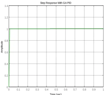
2acceptable. Time domain response GA PIDcontroller tuned via proposed method is shown in Figure-7.
0 0.1 0.2 0.3 0.4 0.5 0.6 0.7 0.8 0.9 1 0
0.2 0.4 0.6 0.8 1 1.2 1.4
Step Response With GA PID
Time (sec)
A
m
p
lit
u
d
e
Figure -7 Step Response with GA PID Controller
Figure-7 shows the time response achieved by the GAPID controller. The PID controller has given better results as compared the H controller i.e. fast rise and settling time, no
over shoot and no steady state error at all.
6.
CONCLUSION
This paper addresses the problem of approximating a fixed-order and fixed-structure PID controller from higher fixed-order H
loop shaping controller using Genetic Algorithm. The main advantage of this algorithm is that a PID controller can be designed in very simple and a systematic way to achieve desired robustness and performance. Example of missile control system has been solved using the proposed algorithm and it has been shown that satisfactory PID controllers can be obtained. The proposed algorithm however has significant shortcoming that the chance of reaching a satisfactory solution depends highly on the initial controllers chosen i.e. pre- and compensators. Consequently, further research is necessary to overcome this problem.
7
.REFERENCES
[1] Doyle J.C. and G.Stein, 1981“Multivariable Feedback design. Concepts for a classical/modern synthesis” IEEE Trans. on Automatic Control, Vol AC-26, PP-4.
[2]
D.J.N. Limebeer,1993, “On the design of robust two degree of freedom controllers” Automatica, Vol 29, Issue 1, Pages 157–168.
[3] Somyot Kaitwanidvilai, 2008, ”Design of Structured Controller Satisfying H∞ Loop Shaping using
Evolutionary Optimization: Application to a Pneumatic Robot Arm” Engineering Letters, 16:2, EL_16_2_03.
[4] Somyot Kaitwanidvilai, and Manukid Parnichkun, 2004 “Genetic-Algorithm-Based Fixed-Structure Robust H∞ Loop-Shaping Control of a Pneumatic Servo-system” Journal of Robotics and Mechatronics Vol.16 No.4.
[5] Wen Tan, Horacio J. Marquez, and Tongwen Chen 2002 “Multivariable Robust Controller Design for a Boiler System” IEEE Transactions on Control Systems Technology, vol. 10, no. 5.
[6] Daniel Ankelhed, 2011, “On design of low order H-infinity Controllers” Department of Electrical Engineering Linköping University, SE–581 83 Linköping, Sweden Linköping.
[7] Fu-Cheng Wan andHsuan-Tsung Chen, 2009, “Design and implementation of fixed-order robust controllers for a proton exchange membrane fuel cell system” International Journal of Hydrogen Energy Volume 34, Issue 6, Pages 2705-2717.
[8] Piyapong Olranthichachat and Somyot
,
Structure Specified Robust H∞ Loop Shaping Control of a MIMO Electro-hydraulic Servo System using Particle Swarm Optimization, Proceeding of IMECS 2011, Vol 2, Hong Kong.[9]
A. U. Genc, “A state-space algorithm for designing H∞ loop shaping PID controllers,” technical report, Cambridge University, Cambridge, UK, Oct. 2000.
[10] McFarlane and K. Glover, 1992 “A Loop Shaping Design Procedure Using H∞ Synthesis” IEEE Transactions on Automatic Control, 37(6) 759-769, June.
[11] Rick Hyde and Jeremy Hodgson, 2000 “Autopilot designs using Mu- Analysis and Synthesis” Math Works MATLAB Digest.
[12] Ian Griffin, 2003, “On-line PID Controller Tuning using Genetic Algorithms” University of Sheffield, Sheffield, UK, page 11-21.
[13] “Modeling Airframe Dynamics” 2004, Aerospace Blockset, Demos, MATLAB 7.
[14] Ejaz, Muhammad, Arbab M.Naeem, Liaq Khan, 2007 “Automatic Weight Selection in H∞ Loop Shaping” Mehran University Research Journal of Engg and Tech., Mehran UET Jamshoro Pakistan, Vol 26.
[image:5.595.82.253.115.268.2]