261
All Rights Reserved © 2017 IJSETR
INVESTIGATION OF EFFECTS OF PROCESS CNC PARAMETERS AND
INSERT GEOMETRY ON HARD TURNING OF STEELS
Mr. A.NARESH, Assistant Professor in The Department of Mechanical Engineering, Guru Nanak Institutions
Technical campus (GNITC) , Ibrahimpatnam, R. R. Dist , Hyderabad, Telangana, India.
MR.BANA KAMMIREDDY, Assistant Professor in The Department of Mechanical Engineering, Guru Nanak
Institutions Technical campus (GNITC) , Ibrahimpatnam, R. R. Dist , Hyderabad, Telangana, India.
Mr.K.VIJAYKUMAR, Assistant Professor in The Department of Mechanical Engineering, Vignan Institute of
Technology and Science, Deshmukhi, R. R. Dist , Hyderabad, Telangana, India.
ABSTRACT
This paper is present study has been done to study the effect of different input parameters on the desired responses on hard turning of different materials. The effect of hardness, material, depth of cut, nose radius, feed and cutting velocity has been evaluated on the machining force, the surface roughness and dimensional deviation. All this has lead to elimination of grinding process which had longer setup times and hard part turning is the upcoming trend which is much fast and précised. This paper is Turning of materials having hardness above 50 HRC (Rockwell scale) is known as hard part turning. Due to technological developments in the area of computerized numerically control machines, it very easy to machine precise components. The development of new tool materials is being used to turn the hard materials at high speeds
Taguchi’s orthogonal array was used to design the experiment. The effect of all the input parameters on the output responses have been analyzed using the analysis of variance. White layer formation, phase analysis and micro strain developed were also studied. Grey relational analysis and Genetic Algorithms were used to determine the optimum combination of input parameters to get the best result.
Keywords: Rockwell Scale, CNC Parameters.
I. INTRODUCTION 1.1 MANUFACTURING
Manufacturing means transformation of raw materials into finished goods for the satisfaction of human needs. To transform the raw material different manufacturing processes are applied because of which the shape, size and physical properties of given material are altered.
Different types of manufacturing process for metals are: -
1. Metal casting: - Casting is a manufacturing process where a solid is melted and heated to certain temperature, then poured into a cavity or mould, the molten metal solidifies in the mould and the desired shape is formed.
2. Metal forming and shaping: - A simple metallic geometry is transformed into a complex one through plastic deformation. Tools or dies impart pressure on the material to transfer the desired geometry through the tool/material interface. It includes rolling, forging, extrusion, drawing, sheet forming, powder metallurgy, molding etc.
262
All Rights Reserved © 2017 IJSETR 3. Joining: - Temporary or permanent joining of same or
different materials. It includes welding, brazing, soldering, diffusion bonding, adhesive bonding, mechanical joining etc.
4. Machining: - It is the metal removing process. It includes turning, boring, drilling, milling, planing, shaping, broaching, grinding etc
5. Finishing operations: - It means improving the surface finish of the material. This includes honing, lapping, polishing, burnishing, deburring, coating, plating processes etc.
6. Material property modification process: - This process involves changing the property of materials to achieve desirable characteristics. This includes hardening, quenching, annealing, case carburizing etc.
7. Advanced manufacturing processes: - It comprises of nontraditional machining. It includes ultrasonic machining, abrasive jet machining, chemical, electric discharge machining, electrochemical machining, high-energy beam machining etc.
1.2 HARD TURNING
Turning of hard materials above 45 HRC is known as hard turning but usually the metals which are hard turned are in the range of 58-62 HRC. It must be noted that hard doesn‟t mean difficult but it stands for high hardness materials. The cutting tools used for hard turning are mainly made of Cubic Boron Nitride (CBN), Ceramic and Cermet. The use of tool depends upon the type of requirement like production quantity and type of surface finish required. Ceramic tool inserts can be used when batch production is to be done but CBN tool inserts are used when mass production is to be done. The selection of the tool depends upon the type of application, if intermittent cutting is to be done a low content CBN tool will not work
well because of low toughness. So a proper insert should be used as per the required application.
A typical hard turned part which is processed on a correctly configured machine, can have surface finishes below .0003 mm, roundness values of .00025 mm and size control as good as .005 mm. Not all machines are suitable for hard part turning. The machines used should have rigidity, power, efficient chip disposal methods and cooling solutions. Such characteristics cannot be achieved on a normal lathe. So as the technology advances CNC turning centers are being used for hard part turning purposes because they are much convenient and easier to use.
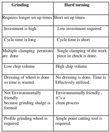
Table 1: Showing comparative difference between grinding and hard turning process
Grinding Hard turning
Requires longer set up times Short set up times
Investment is high Low investment required Cycle time is long Cycle time is short Multiple clamping perations
are done
Single clamping of the work piece in chuck is done. Low chip volume High chip volume Dressing of wheel is done
so time is wasted
No dressing is done. Time is Effectively utilized.
Not Environmentally friendly
because grinding sludge is formed
Environmentally friendly , it‟s a
clean process
Profile grinding wheel is required
Single point cutting tool is required.
II. LITERATURE REVIEW
Davim et al. Used Response Surface Methodology (RSM) to develop model for predicting the surface roughness,
263
All Rights Reserved © 2017 IJSETR specific cutting force, tool wear, power and machining force.
The authors used AISI D2 as work material and used TiN based wiper tool. Selecting cutting speed, feed rate and machining time as parameters and keeping the depth of cut constant, the experiments performed showed that surface roughness value is proportional to feed rate. Flank and crater wear of the tool occurs at high cutting speed. The machining force and the power were more sensitive to feed rate as compared to cutting speed. With increase in machining time the specific cutting force increases as tool wears.
Singh and Rao [18] also developed a surface roughness prediction model by using Response Surface Methodology (RSM). The model developed considered cutting speed, feed and tool geometry (effective rake angle and nose radius) as the parameters. AISI 52100 material and mixed ceramic inserts were used for turning on a high power lathe. The model helped to select the tool geometry so that optimum results can be obtained during hard turning.
III. DESIGN OF STUDY
3.1 PHASES IN THE STUDY
The study can be divided into three phases
1. PHASE 1 : Preliminary study
This phase aimed at detailed study of hard part machining. The effect of various process parameters on the performance of the process was studied and there working limits were identified.
2. PHASE 2 : Experimental setup
In this phase the setup to mount the dynamometer on NC machine was developed with attached computer setup. To ensure desired hardness correct method of hardening was done on the material.
3. PHASE 3: Results and analysis
In this phase the forces and surface roughness were evaluated using ANOVA and the significant and insignificant
parameters were determined. The dimensional deviation was studied. Metallurgical analysis was completed to find the phases present in the material after hard turning. White layer formation and surface pattern was also studied. Grey relational analysis and Genetic algorithm were used to get optimum solutions.
3.2. EXPERIMENTAL DESIGN
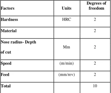
Table 2: Degrees of freedom for various levels
Factors Units
Degrees of freedom Hardness HRC 2
Material 2
Nose radius- Depth
Mm 2
of cut
Speed (m/min) 2
Feed (mm/rev) 2
Total 10
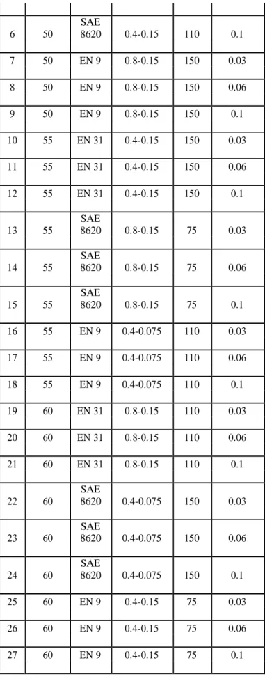
Table 3: L27 Experimental design
Nose
Cutting Hardness Radius(mm)-
S.No. Material speed
Feed (mm/rev) (HRC) depth of (m/min) cut(mm) 1 50 EN 31 0.4-0.075 75 0.03 2 50 EN 31 0.4-0.075 75 0.06 3 50 EN 31 0.4-0.075 75 0.1 4 50 SAE 8620 0.4-0.15 110 0.03 5 50 SAE 8620 0.4-0.15 110 0.06
264
All Rights Reserved © 2017 IJSETR
6 50 SAE 8620 0.4-0.15 110 0.1 7 50 EN 9 0.8-0.15 150 0.03 8 50 EN 9 0.8-0.15 150 0.06 9 50 EN 9 0.8-0.15 150 0.1 10 55 EN 31 0.4-0.15 150 0.03 11 55 EN 31 0.4-0.15 150 0.06 12 55 EN 31 0.4-0.15 150 0.1 13 55 SAE 8620 0.8-0.15 75 0.03 14 55 SAE 8620 0.8-0.15 75 0.06 15 55 SAE 8620 0.8-0.15 75 0.1 16 55 EN 9 0.4-0.075 110 0.03 17 55 EN 9 0.4-0.075 110 0.06 18 55 EN 9 0.4-0.075 110 0.1 19 60 EN 31 0.8-0.15 110 0.03 20 60 EN 31 0.8-0.15 110 0.06 21 60 EN 31 0.8-0.15 110 0.1 22 60 SAE 8620 0.4-0.075 150 0.03 23 60 SAE 8620 0.4-0.075 150 0.06 24 60 SAE 8620 0.4-0.075 150 0.1 25 60 EN 9 0.4-0.15 75 0.03 26 60 EN 9 0.4-0.15 75 0.06 27 60 EN 9 0.4-0.15 75 0.1
Figure 1: ACE CNC jobber xl on which experiment was performed
Figure 2: CNGA 0.8mm nose radius insert, CNGA
0.4
mm nose radius.
IV. RESULTS AND ANALYSIS
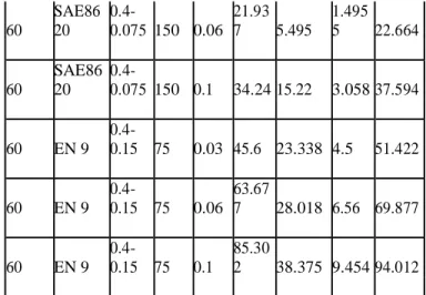
Table 4: Table for machining forces Nose Cutti ng Hardn ess radiu s - Feed Radi al Tangen tial Feed Machi nin Mate rial spee d HRC depth of mm/ rev force( N) force(N ) force( N) g Force( N) m/mi n cut(m m) 50 EN 31 0.4-0.075 75 0.03 17.31 7 8.291 2.327 19.339 50 EN 31 0.4-0.075 75 0.06 23.12 8 9.8856 2.358 25.262 50 EN 31 0.4-0.075 75 0.1 40 17.1 5.641 43.866
265
All Rights Reserved © 2017 IJSETR 50 SAE86 20 0.4-0.15 110 0.03 8.158 6.144 0.362 10.219 50 SAE86 20 0.4-0.15 110 0.06 15.62 3 5.797 0.440 9 16.669 50 SAE86 20 0.4-0.15 110 0.1 50.36 7 22.93 5.705 55.634 50 EN 9 0.8-0.15 150 0.03 6.649 3.3 1.378 7.549 50 EN 9 0.8-0.15 150 0.06 50.29 4 23.25 4.614 55.599 50 EN 9 0.8-0.15 150 0.1 21.65 1 2.172 21.781 55 EN 31 0.4-0.15 150 0.03 18.44 6.573 2.016 5 19.680 55 EN 31 0.4-0.15 150 0.06 20.06 3 10.3279 1.65 22.623 55 EN 31 0.4-0.15 150 0.1 65.96 6 20.209 12.8 70.170 55 SAE86 20 0.8-0.15 75 0.03 54.77 4 26.531 5.506 61.110 55 SAE86 20 0.8-0.15 75 0.06 45.3 20.859 5.93 50.223 55 SAE86 20 0.8-0.15 75 0.1 48.80 6 21.279 2.837 5 53.318 55 EN 9 0.4-0.075 110 0.03 5.011 3.769 0.8 6.321 55 EN 9 0.4-0.075 110 0.06 10.18 4 5.011 1.653 6 11.469 55 EN 9 0.4-0.075 110 0.1 20.37 9 7.4784 2.762 5 21.882 60 EN 31 0.8-0.15 110 0.03 20.94 8.5315 2.074 6 22.706 60 EN 31 0.8-0.15 110 0.06 54.83 6 25.392 4.633 60.607 60 EN 31 0.8-0.15 110 0.1 80.23 5.567 9.132 80.939 60 SAE86 20 0.4-0.075 150 0.03 25.01 9 10.383 3.678 27.336 60 SAE86 20 0.4-0.075 150 0.06 21.93 7 5.495 1.495 5 22.664 60 SAE86 20 0.4-0.075 150 0.1 34.24 15.22 3.058 37.594 60 EN 9 0.4-0.15 75 0.03 45.6 23.338 4.5 51.422 60 EN 9 0.4-0.15 75 0.06 63.67 7 28.018 6.56 69.877 60 EN 9 0.4-0.15 75 0.1 85.30 2 38.375 9.454 94.012
Table 5: Analysis of variance for means of Forces Degree Sum of Source of Variance F valu e Significanc e squares freedom Hardness 2 2627.3 1313.66 5.63 Significant Material 2 58.9 29.46 0.13 Not- Significant Nose radius- 2 2856.1 1428.03 6.12 Significant depth of cut Cutting speed 2 2472.9 1236.44 5.30 Significant Feed 2 3593.1 1796.55 7.70 Significant Residual error 16 3731.2 233.20 Total 26 15339.5
Table 6: Response table for means for forces Depth of
Cutting Level Hardness Material
cut-
Nose Feed speed
radius
266
All Rights Reserved © 2017 IJSETR
2 35.20 37.20 45.59 31.83 37.22
3 51.91 37.77 45.98 31.67 53.24
Delta 23.47 3.38 22.01 20.38 28.17
Rank 2 5 3 4 1
Smaller is better
Figure 3: Main effects plot for means for machining forces.
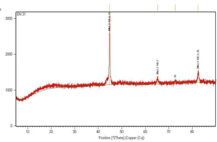
Figure 4: Peaks obtained for virgin sample EN 31
4.1. METALLURGICAL ANALYSIS
Sample EN 31: Virgin sample turned without hardening
Figure 5: SEM image at 200 X for sample number 34
Figure 6: MIAS image for Sample number 34 at 400 X
4.2. COMPARISON BETWEEN HARD TURNED SURFACE AND GRINDING
FINISH SURFACE
267
All Rights Reserved © 2017 IJSETR
Table 7: Thickness of white layer obtained from MIAS
Sample number
Thickness of the white layer in microns
34 9.56
37 9.12
46 7.4
V. RESULTS AND CONCLUSIONS
5.1. RESULTS FOR FORCES AND SURFACE FINISH.
In the experiment Taguchi‟s L27 design was used to
study the effect of hardness, material type, feed, cutting speed and the combined effect of nose radius and depth of cut on the machining forces, surface roughness, dimensional deviation, white layer formation and phase study. ANOVA was used to study the significance of various parameters. Grey relational analysis and Genetic Algorithm was used to design the optimum condition. From the experiment following results were obtained.
5.2. MACHINING FORCES
The dynamometer readings showed that the main dominating force was radial force, tangential force was less than the radial force and feed force was the least. Upon this basis the machining force was mainly influenced by radial component of force.
At feed rate of 0.03 mm/rev, forces were least. As the feed increased the forces also increased.
The cutting velocity of 75 m /min it was observed that maximum force was applied there. As the working range of ceramic inserts was between 100 – 200 m /min. So ceramic inserts should be used in this specified range to get the best possible result.
From 110 m /min to 150 m /min there was no considerable increase in the forces.
Hardness played an important role in increase in the forces. The material type had no significant effect on machining forces.
Nose radius of 0.8 mm had very small increase in the forces. Only depth of cut influenced the machining forces. As the depth of cut increased the machining forces increased.
5.3. SURFACE ROUGHNESS
The best surface finish was obtained on the feed of 0.3 mm/rev.
It was found that on some parameter settings the surface generated was very rough.
Smaller depth of cut had much better surface finish. In comparison at same depth of cut the nose radius of 0.8
mm showed better results.
To get better results cutting speed should fall in the working range of inserts.
VI. CONCLUSIONS
6.1. FORCES AND SURFACE ROUGHNESS
It was found that to get the best results for hard part turning, to achieve best surface finish, and to minimise the machining forces it was necessary that the ceramic inserts used should be in there working range of 100 m /min to 200 m /min and the feed range of 0.03 to 1.5 mm/rev. 0.8 mm nose radius gave the best surface finish. Finishing cut along with less feed should be used to get the best surface finish. Roughing cuts can be given at high feed rate so that there is increase in production rate.
6.2. METALLURGICAL ANALYSIS.
XRD results showed that there was complete change in the phases. The main phase found was Chromium after hard turning of all materials. White layer does not get damaged by etching. The possible reason for the white layer formation was because of Heat affected zone (HAZ) or due to quenching. Distance between two crests was equal to the feed. Micro
268
All Rights Reserved © 2017 IJSETR strain developed on the surface was compressive in nature and
the main reason for this can be because of the formation of white layer.
VII. SCOPE FOR FUTURE WORK
Further investigations are needed to develop the tool material inserts which should be comparatively cheap and last long. Apart from this, work should be done on development of cooling systems for the hard part turning process. So that white layer formation can be minimized. More study is to be done on metallurgical phase changes at different hardness for different materials after and before hard turning. Hard components having larger inner diameters gives roundness errors after hard turning, so work can be done to reduce the roundness errors of shafts by designing a special type chuck which imparts a uniform clamping force on the outer periphery.
REFERENCES
1. http://www.engineershandbook.com/MfgMethods/ accessed on 23rd November, 2010
2. Production technology by R.K Jain, Khanna publishers. ISBN 81-7409-099-1
3. http://en.wikipedia.org/wiki/Turning accessed on 20th November, 2010
4. Manufacturing automation: metal cutting mechanics, machine tool vibrations and CNC design By Yusuf Altintas Cambridge university press 2000
5. American society for metals handbook, volume 3- 8th edition
6. Textbook of production engineering by K. C. Jain, Chitale A. K , PHI learning , ISBN: 978-81-203-3526-4. 7.
http://www.mech.unimelb.edu.au/manuf-sci3/436413/tool_wear.htm accessed on 25th November, 2010
8. http://www2.coromant.sandvik.com/coromant/pdf/H ard_part_turning/C-1040-069.pdf Sandvik coromant hard part turning journal accessed on 20th
November, 2010
9. Hemburg machine tools page
http://www.hembrug.com/page.aspx?PageID=11 accessed on 20th November, 2010
10. http://www.hardinge.com/usr/pdf/hardturn/ASME.pdf accessed on 20th November, 2010
11. http://www.fandmmag.com/publication/article.jsp?pubId= 1&id=504&pageNum=1 Fabricating and metalworking- march 2002 issue – magazine article- tips on hard turning by Mike Riley. Accessed on 20th November, 2010. 12. American machinist
http://www.americanmachinist.com/304/Issue/Arti cle/False/67704/Issue accessed on 21st November, 2010
13. Machinery‟s handbook 24th edition, industrial press inc, isbn 0-8311-2492-X
14. http://www.ntkcuttingtools.co.uk/Ceramics.html accessed on 4th June, 2011
Mr. A.NARESH
I completed my SSC in 2003 from Govt MB High School Devarakonda, Diploma in Mechanical Engineering from Govt Polytechnic Nalgonda in 2007, B.Tech Mechanical Engineering from SRTIST JNTU HYDERABAD in 2011, M.Tech(CAD/CAM) from Brilliant Group Of Institutions JNTU Hyderabd in 2015. I was active member in establishing the laboratories and other facilities of the Department. I got a total teaching experience of 4 years and 06 students awarded B.Tech under my guidance for their M.Tech(CAD/CAM). Now I am working as Assistant Professor In The Department of Mechanical Engineering, Guru Nanak Institutions Technical Campus (GNITC) , Ibrahimpatnam, R. R. Dist
269
All Rights Reserved © 2017 IJSETR ,Hyderabad , Telangana, India.
Mr.Bana KammiReddy
Now I am working as Assistant Professor In The Department of Mechanical Engineering, Guru Nanak Institutions Technical Campus (GNITC) , Ibrahimpatnam, R. R. Dist ,Hyderabad , Telangana, India.
Mr. K. VIJAYKUMAR
I done my SSC in 2004 from Z.P.H.S G.Yadavally (v), Kangal (M), Nalgonda (D), Intermediate in Don Bosco Junior Collge in 2006, B-Tech Mechanical Engineering from SRTIST JNTU HYDERABAD in 2011, M.Tech Specialization Machine Design from Holy Mary Institute of Technology & Science College JNTU Hyderabd in 2014. I started my career as Asst Professor at Kasireddy Narayanreddy College of Engineering and Research, Hyderbad, I am working many engineering collages , SCIENT, AVANTHI, GREENFORT, GURU NANAK Now I am working as Assistant Professor In The Department of Mechanical Engineering, vignan institute of technology and science, Deshmukhi (v), Pochampally (m), Hyderabad, TS. I am previously many journals Published.