Applied sequential-search algorithm for
compression-encryption of high-resolution structured light 3D data
SIDDEQ, M and RODRIGUES, Marcos
<http://orcid.org/0000-0002-6083-1303>
Available from Sheffield Hallam University Research Archive (SHURA) at:
http://shura.shu.ac.uk/10047/
This document is the author deposited version. You are advised to consult the
publisher's version if you wish to cite from it.
Published version
SIDDEQ, M and RODRIGUES, Marcos (2015). Applied sequential-search algorithm
for compression-encryption of high-resolution structured light 3D data. In: BLASHKI,
Katherine and XIAO, Yingcai, (eds.) MCCSIS : Multiconference on Computer
Science and Information Systems 2015. IADIS Press, 195-202.
Copyright and re-use policy
See
http://shura.shu.ac.uk/information.html
1
APPLIED SEQUENTIAL-SEARCH ALGORITHM FOR
COMPRESSION-ENCRYPTION OF HIGH-RESOLUTION
STRUCTURED LIGHT 3D DATA
M. M. Siddeq and M. A. Rodrigues
GMPR-Geometric Modelling and Pattern Recognition Research Group, Sheffield Hallam University, Sheffield, UK
[email protected], [email protected]
ABSTRACT
A new image compression algorithm is proposed and demonstrated in the context of structured light 3D reconstruction. Structured light images contain patterns of light, which are captured by the sensor at very high resolution. The algorithm steps involve a two level Discrete Wavelet Transformation (DWT) followed by a Discrete Cosine Transformation (DCT) to generate a DC-Column and an MA-Matrix (Multi-Array Matrix). The MA-Matrix is then partitioned into blocks and a minimization algorithm codes each block followed by arithmetic coding. At decompression stage a new proposed algorithm, Sequential-Search Algorithm (SS-Algorithm) is used to estimate the MA-Matrix. Thereafter, all decompressed DC-Columns are combined with the MA-Matrix followed by inverse DCT and inverse DWT. The effectiveness of the algorithm is demonstrated within a 3D reconstruction scenario from structured light images.
KEYWORDS
Discrete Wavelet Transform; Discrete Cosine Transform; Minimize Matrix Size Algorithm; Sequential Search Algorithm; Structured Light; 3D reconstruction.
1.
INTRODUCTION
2
The focus of this paper is on compression of structured light images. Such images contain patterns of light allowing 3D reconstruction. A possible scenario would be a surface patch compressed as a 2D image together with 3D calibration parameters, transmitted over a network and remotely reconstructed (geometry, connectivity and texture map) at the receiving end with the same resolution as the original data. The widespread integration of 3D models in different fields motivates the need to be able to store, index, classify, and retrieve 3D objects automatically and efficiently.
Siddeq and Rodrigues [12] proposed 2D image compression methods based on high-frequency sub-bands compressed by the Minimize-Matrix-Size Algorithm (MMS) and decompressed by the Limited-Sequential Search Algorithm (LSS). The advantages are high compression ratios with high-resolution 3D reconstruction. However, the complexity of the algorithm means very large execution times that could be in the order of minutes. A new algorithm was proposed [13] using JPEG, with decompression by a parallel SS-Algorithm. The execution time was reduced to a few seconds with higher compression ratios. Recently, a novel algorithm was proposed [22] for decompression of DCT coefficients called Fast Matching Search (FMS), which reduced execution time to milliseconds. Further, the FMS algorithm was applied to frequency sub-bands of DWT followed by DCT [23]. In this research we introduce a new method for compression and encryption by partition the DCT coefficients into blocks and applying the MMS-Algorithm on each block of pixels. Each block generates a unique key at compression stage. This key can be seen as a symmetric encryption key, as without the key the block cannot be decoded.
2.
THE PROPOSED COMPRESSION-ENCRYPTION ALGORITHM
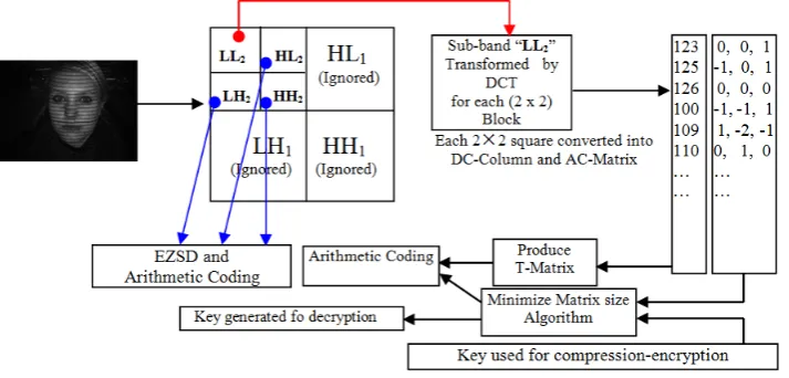
[image:3.595.132.489.435.606.2]The proposed algorithm uses two transformations: a two level DWT converts an image into seven frequency sub-bands. The low-frequency sub-band is divided into 2x2 non-overlapped blocks and a DCT is applied to each block. The DCT is very important to increase high-frequency domains by converting LL2 into DC-coefficients and AC-DC-coefficients (DC-Column and MA-Matrix). The Minimize-Matrix-Size Algorithm is applied to MA-Matrix for encryption and then subject to arithmetic coding together with DC-Column as depicted in Fig. 1.
Figure 1.Layout of proposed Compression-Encryption algorithm
2.1. Discrete Wavelet Transform (DWT)
3
fact that much of the important information is contained in the LL2 sub-band. In particular, the Daubechies
wavelet transform has the ability to reconstruct approximately the original image by just using second level sub-bands (LL2, HL2, LH2 and HH2), while other sub-bands can be ignored. This property allows higher
compression ratios [18,19].
2.2. Discrete Cosine Transform (DCT)
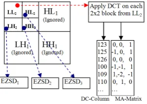
A second transform is applied to each 2x2 block of pixels of LL2 sub-band as show in Fig. 2. The energy in
[image:4.595.237.387.273.379.2]the transformed coefficients is concentrated about the left corner of the matrix of coefficients. The top-left coefficients correspond to low frequencies: there is a 'peak' in energy in this area and the coefficients values rapidly decrease to the bottom right of the matrix, which means the higher-frequency coefficients [7,9]. The DCT coefficients are de-correlated, which means many of the small values (coefficients) can be discarded without significantly affecting image quality. A compact matrix of de-correlated coefficients can be compressed much more efficiently than a matrix of highly correlated pixels [8,17].
Figure 2. LL2 sub-band quantized and transformed by DCT for each 2x2 blocks
Quantization is performed by matrix-dot-division and then truncating the result, by dividing each 2x2 coefficient from LL2. The quantized matrix removes insignificant coefficients. In the proposed method the high frequency sub-bands at first level are set to zero (i.e. discard HL1, LH1 and HH1) as they do not affect
image details. Additionally, only a small number of non-zero values are present in these sub-bands. In contrast, high-frequency sub-bands in the second level (HL2, LH2 and HH2) cannot be discarded, as this
would significantly affect image quality. For this reason, high-frequency values in this region are quantized. The quantization Q depends on the maximum value in each sub-band as follows:
Q=Quality*
max
H
(1)where the matrix H refers to the high-frequency coefficients in HL2, LH2 and HH2, the factor Quality is used
to increase/decrease H. Thus, image details are reduced in case Quality >=0.01. The limit range for this factor is less than or equal to 0.9 for the 3D data used in this paper.
3.
MINIMIZE-MATRIX-SIZE ALGORITHM (ENCRYPTION)
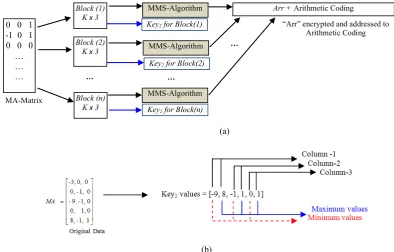
The purpose of this algorithm is to reduce the size of the MA-Matrix. This process depends on a key value and three adjacent coefficients to calculate and store the sum in a new array. The MMS algorithm consists of two parts: first, the MA-Matrix is partitioned into non-overlapping blocks (Kx3) of coefficients, where K refers to number of rows in a block as shown in Fig. 3(a). Second, each block is encrypted by a Key1 value. Additionally, new key values are generated for each block called Key2. Each key from each block is organized as minimum and maximum value for each column as shown in Fig. 3(b). Each row and column
(r,c) of the MA matrix is coded as follows:
(r,c)
Arr
=(r,c)
Key
1
*MA
(r,c)+(r,c)
Key
1
*MA
(r,c)+(r,c)
4
The Arr contains stream of encrypted values. Thereafter, Arr is compressed by using arithmetic coding to produce stream of bits. The key1 values are used in the Minimize-Matrix-Size Algorithm generated randomly, these key values are between {0…1} (for example; Key1= {0.128, 0.65, 0.8519}).
(a)
(b)
Figure 3. (a) MA-Matrix divided into blocks and each block encrypted by MMS-Algorithm, (b) Key2 Values generated from a block, as an example block size =5.
4.
TRANSFORMED MATRIX (T-MATRIX)
The DC-Column contains the DC values of DCT partitioned into 64-arrays. Each array is transformed by one-dimensional DCT, thereafter the quantization process is applied to each array as per Eq. (3) and then stored in a matrix called Transformed-Matrix (T-Matrix).
n
Q
=Q
(n!1)+1 (3) [image:5.595.98.493.141.393.2]where 64 ≥ n ≥1.The values in Matrix are de-correlated yielding good compression ratio. Each row of T-Matrix consists of low and high frequency coefficients. After scanning column-by-column, the T-T-Matrix is transformed into one-dimensional array which is then subject to Arithmetic Coding [8]. Fig. 4 illustrates the process.
Figure 4. T-Matrix technique 0 0 1
-1 0 1 0 0 0
… … …
Block (1) K x 3
Block (2) K x 3
Block (n) K x 3
MMS-Algorithm
MMS-Algorithm
MMS-Algorithm Key2 for Block(1)
Key2 for Block(2)
Arr + Arithmetic Coding
Key2 for Block(n)
MA-Matrix
… …
…
[image:5.595.163.462.592.677.2]5
5.
ELIMINATE ZEROS AND STORE DATA (EZSD)
The EZSD algorithm is designed to increase compression ratio for high frequency sub-bands, and it is applied to each sub-band independently. It eliminates block of zeros, saving blocks of nonzero data in an array. The algorithm starts to partition the high-frequency sub-bands into non-overlapping 8x8 blocks, and then searches for nonzero blocks (i.e. search for at least one nonzero data inside a block). If the block contains any data, this block will be stored in the array called Reduced-Array; also the coordinates for the nonzero block are stored in new array called Positions. If the block contains just zeros, this block will be ignored, and the algorithm continues to search for other nonzero blocks. The final obtained Reduced Array is subject to Arithmetic Coding.
6.
DECOMPRESSION BY SEQUENTIAL SEARCH (SS-ALGORITHM)
The decompression-decryption algorithm consists of four steps. First, arithmetic decoding is used to recover the one-dimensional-array containing the original data in the T-Matrix, illustrated in Fig. 5(a). Second, the novel SS-Algorithm is applied for decoding the MA-Matrix. This novel algorithm depends on the coded Arr, Key1 and Key2 as illustrated in Fig. 5(b). The encrypted array is partitioned into sub-arrays of size K. Each
sub-array is subject to SS-Algorithm to recover the block of data in the MA-Matrix.
(a) (b)
Figure5. (a) Decoding the DC-Column; (b) Decoding the MA-Matrix through the SS-Algorithm
The SS-Algorithm using three pointers, these pointers refer to original data in specific blocks of the MA-Matrix. The initial values of these pointers are set to minimum in the space search (Key2). These three pointers are called S1, S2 and S3 and are incremented by one in a gearwheel (e.g. similar to a clock, where S1, S2 and S3 represent hour, minutes and seconds respectively). At each iteration the SS-Algorithm computes the sum Eq. (4) and compares the error in Eq. (5) with zero. If true, the estimated values are S1, S2 and S3 corresponding to the original values in the MA-Matrix. In case of E ≠ 0, the algorithm will continue to search for the original values in the block.
Sum = S(i)!Key1(i)
i=1
3
"
(4)E= Arr!Sum (5)
6
7.
EXPERIMENTAL RESULTS
The experimental results described here were implemented in MATLAB R2013a and Visual C++ 2008 running on an AMD Quad-Core microprocessor. We apply the compression and decompression algorithms to 2D images obtained from the GMPR scanner [13,14]; these images contain structured light patterns allowing 3D surface data to be generated from those patterns (Fig 6). The principle of operation of GMPR 3D surface scanning is to project patterns of light onto the target surface whose image is recorded by a camera. The shape of the captured pattern is combined with the spatial relationship between the light source and the camera, to determine the 3D position of the surface along the pattern. A surface can be scanned from a single 2D image and processed into 3D surface in a few milliseconds [15].
(a) (b)
Figure 6. (a) The 3D scanner captures a 2D image containing structured light; (b) 3D surface reconstruction from the 2D image using GMPR software
[image:7.595.98.511.224.336.2]FACE1 FACE2 WALL Figure 7. 2D images used in this research (dimension: 1392 x 1040 pixels, size: 1.38 MB)
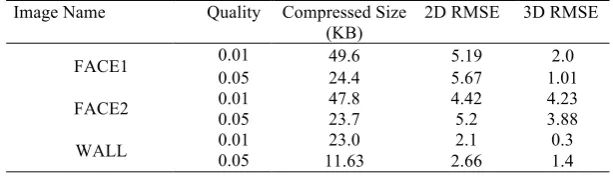
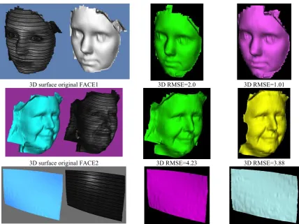
In this research we use 3 images depicted in Fig 7; these will be subject to compression followed by 2D to 3D reconstruction. The justification for introducing 3D reconstruction is that we can make use of a new set of metrics in terms of error measures and perceived quality of the 3D visualization to assess the quality of the compression and decompression algorithms. The rationale is that high quality image compression is required, otherwise the resulting 3D structure from the decompressed image will contain apparent dissimilarities and artefacts when compared to the 3D structure obtained from the original (uncompressed) data. We report on these differences through standard measures of RMSE-root mean square error as shown in Table 1. Additionally Fig. 8 shows visualization of 3D reconstruction compared with original (uncompressed) images.
Table 1. Compression-encryption applied to 2D images followed by 2D to 3D reconstruction Image Name Quality Compressed Size
(KB)
2D RMSE 3D RMSE
FACE1 0.01 49.6 5.19 2.0
0.05 24.4 5.67 1.01
FACE2 0.01 47.8 4.42 4.23
0.05 23.7 5.2 3.88
WALL 0.01 23.0 2.1 0.3
[image:7.595.103.510.372.498.2] [image:7.595.151.458.630.718.2]7
3D surface original FACE1 3D RMSE=2.0 3D RMSE=1.01
[image:8.595.88.517.89.410.2]3D surface original FACE2 3D RMSE=4.23 3D RMSE=3.88
Figure 8. Comparison of 3D surface reconstruction using the original (uncompressed) images on the left, with compressed images on the right with RMSE measures.
8.
CONCLUSIONS
This research has presented and demonstrated a novel method for 2D image compression and encryption. The quality of the method is illustrated through 2D to 3D reconstruction, 2D and 3D RMSE and the perceived quality of the visualization. The method is based on DWT and DCT in connection with the MMS algorithm. The results show that the proposed approach is capable of accurate 3D reconstructing with high compression ratios. The algorithm’s advantages are highlighted as follows.
1. Using two transformations results in an increased number of high-frequency coefficients, leading to higher compression ratios.
2. The properties of the Daubechies wavelets are useful to obtain higher compression ratios; this is because high frequencies from the first level can be ignored without loss of accuracy.
3. The Minimize-Matrix-Size-Algorithm is used to partition the MA-Matrix into blocks and each row in each block are converted to a single value by Key1. Additionally, it generates Key2 for each block
to increase the encryption level, thus Key1 and Key2 are both used in decryption step.
4. The SS-Algorithm (Decryption algorithm) represents the core of the decompression-decryption algorithm, which recovers the MA-Matrix by using encrypted data with Key1 while Key2 is used to
specify the space search for each block in the recovered MA-Matrix.
8
The approach disadvantages are summarized as follows. The overall complexity of the approach leads to increased execution time for both compression-encryption and decompression-decryption; the SS-Algorithm iterative method is particularly complex. Future work includes tackling the complexity of the method and developing alternative approaches to encoding and decoding the key management methods.
REFERENCES
[1] ADNAN KHASHMAN, KAMIL DIMILILER, 2008, Image Compression using Neural Networks and Haar Wavelet, WSEAS TRANSACTIONS on SIGNAL PROCESSING, Vol. 4, No.5.
[2] Ali Al-Haj, 2007, Combined DWT-DCT Digital Image Watermarking, Science Publications, Journal of Computer Science 3 (9): 740-746.
[3] Chen C. S. and Chen R. J, 2006, Image Encryption and Decryption using SCAN Methodology, Proceedings of seventh International Conference on Parallel and Distributed Computing, Application and Technologies
(PDCAT’06), pp.61-66.
[4] El-Khamy S. E., Lotfy M. and Ali A. H, A New Color Image Encryption Technique utilizing Fuzzy Pseudo-random Bit Generator, Proceedings of 22nd National Radio Science Conference (NRSC), pp.185-194, Mar 2005.
[5] Grigorios D. , N. D. Zervas, N. Sklavos and Costas E. Goutis , 2008, Design Techniques and Implementation of Low Power High-Throughput Discrete Wavelet Transform Tilters for JPEG 2000 Standard, WASET , International Journal of Signal Processing, Vo. 4, No.1.
[6] G.Sadashivappa and K.V.S.Ananda Babu, 2008, PERFORMANCE ANALYSIS OF IMAGE CODING USINGWAVELETS, IJCSNS International Journal of Computer Science and Network Security, VOL.8 No.10. [7] I. E. G. Richardson, 2002, Video Codec Design, John Wiley & Sons.
[8] K.Sayood, 2000, Introduction to Data Compression, 2nd edition, Academic Press, Morgan Kaufman Publishers. [9] K. R. Rao, P. Yip, 1990, Discrete cosine transform: Algorithms, advantages, applications, Academic Press, San
Diego, CA.
[10]M. Antonini, M. Barlaud, P. Mathieu, and I. Daubechies, 1992, Image coding using wavelet transform,” IEEE Trans. on Image Processing, Vol. 1, No. 2, pp. 205–220.
[11]Mitra A., Subba Rao Y. V. and Prasanna S. R. M, 2006, A New Image Encryption Approach using Combinational Permutation Techniques, International Journal of Computer Science, Vol. 1, No. 2, pp. 127-131.
[12]M. M. Siddeq, M. A. Rodrigues 2014a, A Novel Image Compression Algorithm for high-resolution 3D Reconstruction, 3D Research. Springer Vol. 5 No.2. DOI 10.1007/s13319-014-0007-6
[13]M. M. Siddeq, M. A. Rodrigues, 2014b, A New 2D Image Compression Technique for 3D Surface Reconstruction,
18th International Conference on Circuits, Systems, Communications and Computers, Santorin Island, Greece: 379-386
[14]M. Rodrigues, A. Robinson and A. Osman, 2010. Efficient 3D data compression through parameterization of free-form surface patches, In: Signal Process and Multimedia Applications (SIGMAP), Proceedings of the 2010 International Conference on IEEE, 130-135.
[15]M. Rodrigues, A. Osman and A. Robinson, 2013, Partial differential equations for 3D data compression and reconstruction, Journal Advances in Dynamical Systems and Applications, Vol. 8 No. 2, 303-315.
[16]M. Rodrigues, M. Kormann, Schuhler and C. Tomek, P 2013. Structured Light Techniques for 3D Surface Reconstruction in Robotic Tasks. In: KACPRZYK, J, (ed.) Advances in Intelligent Systems and Computing. Heidelberg, Springer, 805-814.
[17]N. Ahmed, T. Natarajan and K. R. Rao, 1974. Discrete cosine transforms, IEEE Transactions Computer, Vol. C-23, pp. 90-93.
[18]Rafael C. Gonzalez, Richard E. Woods 2001, Digital Image Processing, Addison Wesley publishing company. [19]T. Acharya and P. S. Tsai. 2005, JPEG2000 Standard for Image Compression: Concepts, Algorithms and VLSI
Architecture. New York: John Wiley & Sons.
[20]Tsai, M. and H. Hung, 2005, DCT and DWT based Image Watermarking Using Sub sampling, in Proc. Of the 2005 IEEE Fourth Int. Conf. on Machine Learning and Cybernetics, pp: 5308-5313, China.
[21]Yen J. C. and Guo J. I, 1999, A New Image Encryption System and its VLSI Architecture”, IEEE Workshop on Signal Processing Systems, Taipei, pp.430-437.
[22]MM Siddeq and MA Rodrigues, 2015. A Novel Image Compression Method based on DCT and Decompressed by Parallel Fast Matching Search Algorithm. Submitted to EURASIP Journal on Image and Video Processing.