David Sanderson1[0000-0002-8675-4991] and Jack C Chaplin1[0000-0003-3282-2386] and Svetan Ratchev1[0000-0001-9955-2806]
1 Institute for Advanced Manufacturing, Advanced Manufacturing Building, Jubilee Campus,
University of Nottingham, UK, NG8 1BB
(firstname.lastname)@nottingham.ac.uk
Abstract. The design and reconfiguration of adaptive production systems is a key driver in modern advanced manufacturing. We summarise the use of an ap-proach from the field of functional modelling to capture the function, behaviour, and structure of a system. This model is an integral part of the Evolvable Assem-bly Systems architecture, allowing the system to adapt its behaviour in response to changing product requirements. The integrated approach is illustrated with an example taken from a real EAS instantiation.
Keywords: Architecture, Evolvable Assembly Systems, Functional Modelling, Multi-Agent Systems.
1
Introduction
The manufacturing industry as a whole is facing increased market unpredictability and labour costs, as well as growing consumer demand for highly personalised goods and services with a shorter time to market and increased product diversity [1]. In order to incorporate these changes, manufacturing systems have begun to take advantage of adaptive control for flexibility, resilience, and monitoring. Manufacturing companies in many sectors are therefore investigating smart, flexible, and adaptive manufacturing lines that can autonomously self-heal, self-adapt, and reconfigure in response to chang-ing product requirements. This is typified by the ‘batch-size-of-one’ problem, wherein each product may be unique and the manufacturing system must be capable of carrying out different production processes as required by the current product.
A common approach to these problems is that of cyber-physical systems [2], often implemented as a multi-agent system [3]. One such implementation is that of the Evolv-able Assembly Systems project [4], which combines a behavioural framework based on functional modelling with a multi-agent cyber-physical systems architecture.
2
Functional Modelling
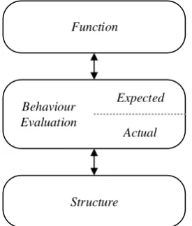
of a production resource: by considering the processes that the resource can perform, and by considering how their structure and behaviour relate to their intended functions. We take the second approach, based on the Function-Behaviour-Structure (FBS) for-malisations by Gero, Rosenman, Umeda, and others in the field of functional modelling [5–11]. Consequently, we define Function as an abstraction of behaviour for a specific use or purpose, Behaviour as state transitions from input to output, and Structure as the physical model of the system and subsystem, and the connections between them.
Fig. 1. Overview of the functional modelling behavioural approach
The behavioural framework shown in Fig. 1 is at the core of the Evolvable Assembly Systems approach. The required set of functions is used to determine the behaviours that are expected to fulfil those functions. The structure of the system is then designed, and the actual behaviour expressed by that structure is compared to the expected be-haviour. The algorithmic basis for this process of distributed behavioural evaluation is described in more detail in [12].
Each resource in the system consists of some structure and corresponding behav-iour(s). Some resources also have multiple configurations. These are managed by an intelligent agent; all agents in the system communicate with each other to provide dis-tributed control based on a joint system model that provides both operational data, and the coordination for the distributed behavioural evaluation.
Behaviour Evaluation
Expected
Actual
3
Evolvable Assembly Systems
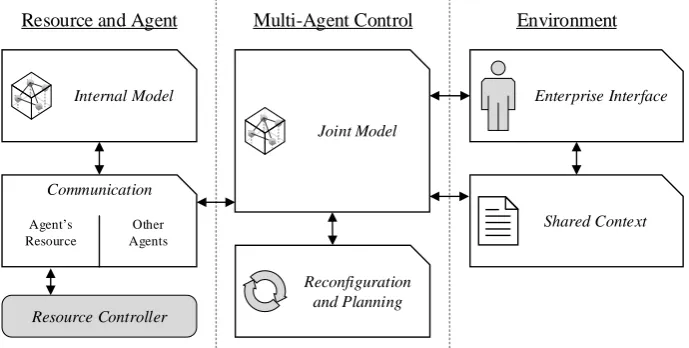
Fig. 2. An agent-oriented view of EAS architecture
An agent-oriented view of the EAS architecture is shown in Fig. 2. Each resource in the system is controlled at a high level by an intelligent agent – an encapsulated piece of software that makes control decisions based on available information. Evolvable As-sembly Systems uses the Beliefs-Desires-Intentions agent paradigm [13], so this infor-mation is stored as beliefs, and translated into immediate intentions (plans) in order to accomplish long term desires (goals). The intentions of the agent are executed through behaviour in the system, based on the behaviours that can be expressed by the structure of the resource that is being controlled.
Each resource in the system can be defined as a set of structures and associated be-haviours using Business to Manufacturing Markup Language (B2MML) based on the ISA-95 standard [14, 15]. To enable an agent to control a resource, this description is used to generate an interface. This interface connects the agent with the PLC, controller, or similar that provides the low-level control for the resource hardware. This interface layer allows the agent core to remain the same whilst still providing control for a variety of hardware archetypes.
4
Shared Context
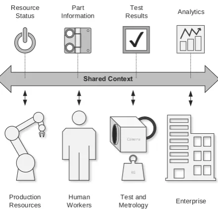
Although each agent is responsible for local control of the resource it is attached to, the collection of agents provide a distributed agent control layer for the whole production system. Communication between these agents is based on the ubiquitous sharing of contextual information.
This contextual information covers all aspects of the system. At the most fundamen-tal level, it describes the product that is to be produced by the system, and the
produc-Resource and Agent Multi-Agent Control Environment
Resource Controller
Internal Model Enterprise Interface
Reconfiguration and Planning
Shared Context Communication
Agent s Resource
Other Agents
tion capabilities of each resource in the system as well as any “joint capabilities” re-sulting from combinations of resources. This is further enhanced by information about the state of the product and system, for example the pose of a robot arm, the location of a pallet, or relevant metrology data. The context also provides a link between the EAS control system and the rest of the enterprise in which it is situated. This may include control systems for other assembly cells, or higher-level enterprise information sys-tems. All of this information is stored in a context layer that is accessible to all agents as required. This shared context is implemented using a publish-subscribe data distri-bution service [16] and illustrated in Fig. 3.
Fig. 3. Shared context data distribution
5
Implementation Example
This system has been implemented in a real precision assembly demonstrator (PAD) at the University of Nottingham, shown in Fig. 4. The demonstrator is designed to assem-ble interior hinges from the automotive industry. Each product is defined by a recipe file that indicates the détente force – achieved by the configuration of ball-spring pairs added to the hinge. Because each hinge produced by the system could be unique, these recipe files are a way to formalise the batch-size of one requirements in the system.
Part Information
Test
Results Analytics
Resource Status
Production Resources
Human Workers
KG Camera
Test and
Fig. 4. The Precision Assembly Demonstrator (PAD)
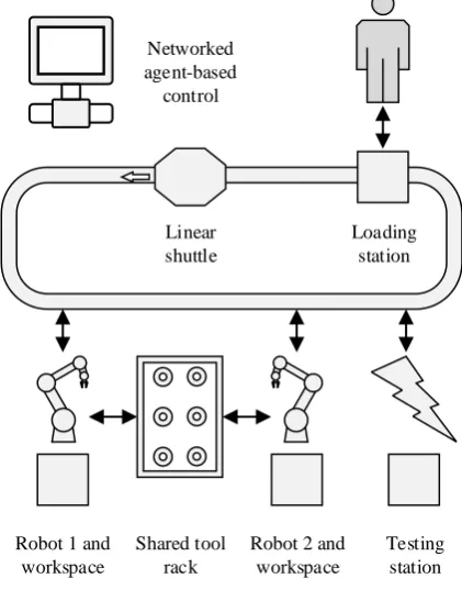
Fig. 5. Layout of the PAD Linear
shuttle Networked agent-based
control
Loading station
Robot 1 and workspace
Testing station Robot 2 and
workspace Shared tool
[image:5.595.192.403.384.653.2]The demonstrator is based on a Feintool Modutec assembly cell, and consists of two KUKA KR5 sixx R650 robots alongside a testing station with visual inspection and force testing equipment, connected via a linear shuttle system. Each robot has an indi-vidual working area, as does the testing station. The robots share a tool rack, giving them each access to a variety of different end effectors via an automatic tool changer. The whole system is accessible via a part loading station, where pallets of unassembled parts are loaded, and pallets with completed products are removed. A diagram of the demonstrator can be seen in Fig. 5.
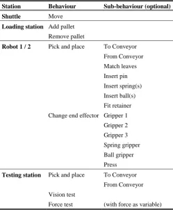
Table 1. Behaviours available to each station in the PAD
Station Behaviour Sub-behaviour (optional)
Shuttle Move
Loading station Add pallet Remove pallet
Robot 1 / 2 Pick and place To Conveyor From Conveyor Match leaves Insert pin Insert spring(s) Insert ball(s) Fit retainer Change end effector Gripper 1
Gripper 2 Gripper 3 Spring gripper Ball gripper Press
Testing station Pick and place To Conveyor From Conveyor Vision test
Force test (with force as variable)
the system, and remove parts from the system. Note that for readability of Table 1 we have not shown the dependencies between end effector and pick and place behaviours. For example, the “spring gripper” end effector is required to fit a spring, but grippers 1-3 are interchangeable for some other tasks (moving the pallet, etc). More detail on the physical demonstration platform itself can be found in [17].
These behaviours are then adapted by the agent controlling the relevant resource in order to produce the product specified by the recipe file – that is, accomplish the re-quired function inherent in the new product. Each agent may further be able to adapt some or all of the structure of its resource. In the case of our example, the shared tool rack provides a selection of end effectors. The selection of a new end effector changes both the structure and behaviour of the resource.
As the “loading station” behaviours are carried out by an operator they are logically part of the system, but do not have to be programmed into an agent – the operator only needs some way to tell the rest of the system what behaviour has been carried out.
6
Summary and Acknowledgements
This paper has described the agent-oriented architecture of Evolvable Assembly Sys-tems in the context of the FBS approach from function modelling. This approach allows the system to accurately model the adaptive structure and behaviour of the system, and leverage them to achieve the system functions required by the changing product re-quirements of a batch-size of one scenario. This approach has been demonstrated on a real demonstration cell at the University of Nottingham.
The authors gratefully acknowledge the support provided by UK EPSRC Evolvable Assembly Systems (EP/K018205/1).
References
1. Kagermann, H., Helbig, J., Hellinger, A., Wahlster, W.: Recommendations for Implementing the Strategic Initiative INDUSTRIE 4.0: Securing the Future of German Manufacturing Industry; Final Report of the Industrie 4.0 Working Group. (2013). 2. Monostori, L.: Cyber-physical Production Systems: Roots, Expectations and R&D
Challenges. Procedia CIRP. 17, 9–13 (2014).
3. Wooldridge, M., Jennings, N.R.: Intelligent agents: Theory and practice. Knowl. Eng. Rev. 10, 115–152 (1995).
4. Chaplin, J.C., Bakker, O.J., de Silva, L., Sanderson, D., Kelly, E., Logan, B., Ratchev, S.M.: Evolvable Assembly Systems: A Distributed Architecture for Intelligent Manufacturing. IFAC-PapersOnLine. 48, 2065–2070 (2015).
5. Gero, J.S.: Design Prototypes: A Knowledge Representation Schema for Design. AI Mag. 11, 26–36 (1990).
6. Gero, J.S., Kannengiesser, U.: A function–behavior–structure ontology of processes. AI EDAM Artif. Intell. Eng. Des. Anal. Manuf. 21, 379–391 (2007).
8. Umeda, Y., Takeda, H., Tomiyama, T., Yoshikawa, H.: Function, behaviour, and structure. In: Applications of Artificial Intelligence in Engineering V. pp. 177–193 (1990).
9. Umeda, Y., Ishii, M., Yoshioka, M., Shimomura, Y., Tomiyama, T.: Supporting conceptual design based on the function-behavior-state modeler. Artif. Intell. Eng. Des. Anal. Manuf. 10, 275–288 (1996).
10. Sasajima, M., Kitamura, Y.: FBRL: A Function and Behavior Representation Language. In: Proceedings of the 14th International Joint Conferences on Artificial Intelligence (IJCAI). pp. 1830–1836 (1995).
11. Mizoguchi, R., Kitamura, Y.: Foundation of Knowledge Systematization: Role of Ontological Engineering. In: Industrial Knowledge Management. pp. 17–36. Springer London, London (2001).
12. de Silva, L., Felli, P., Chaplin, J.C., Logan, B., Sanderson, D., Ratchev, S.: Synthesising Industry-Standard Manufacturing Process Controllers. In: Proceedings of the 16th Conference on Autonomous Agents and MultiAgent Systems. pp. 1811–1813. International Foundation for Autonomous Agents and Multiagent Systems (2017). 13. Rao, A.S., Georgeff, M.P.: BDI agents: From theory to practice. In: Proceedings of the
first international conference on multi-agent systems (ICMAS-95). pp. 312–319. San Francisco, CA (1995).
14. Business To Manufacturing Markup Language Operations Schedule Version 6.0, https://services.mesa.org/ResourceLibrary.
15. ANSI/ISA-95, Enterprise-Control System Integration, Parts 1-5, https://www.isa.org/standards-publications/.
16. Data Distribution Service, http://www.omg.org/spec/DDS/Current.