ISSN Print: 2327-4352
DOI: 10.4236/jamp.2018.611205 Nov. 30, 2018 2445 Journal of Applied Mathematics and Physics
A Deep-Water Bottom Reverberation Model
Based on Ray Theory
Longhao Wang
1,2, Jixing Qin
1*, Zhenglin Li
1, Jianjun Liu
11State Key Laboratory of Acoustics, Institute of Acoustics, Chinese Academy of Sciences, Beijing, China 2College of Meteorology and Oceanology, National University of Defense Technology, Changsha, China
Abstract
Ocean reverberation is an important issue in underwater acoustics due to the significant influence on working performance of the active sonars. In this pa-per, a uniform bottom-reverberation model is proposed based on ray theory, which can calculate monostatic and bistatic reverberation intensity and ex-plain the generation process of deep-water reverberation. The mesh method is firstly used in this model by dividing bottom scatterers into a number of grids. Then reverberation is calculated based on the exact time of scattering signal generated on each grid. Due to exact arrival time, the presented model can provide more accurate result than classical models, in which scatterers are usually treated as circular rings or elliptical rings. Numerical results are compared with reverberation data collected from the South China Sea deep-water experiment with different receiving distances and depths. The simulated and experimental results agree well overall.
Keywords
Bottom Reverberation, Deep Water, Ray Theory
1. Introduction
Reverberation is an important subject in the field of ocean acoustics. Ocean re-verberation is usually the main background interference of active sonars, and it is also widely concerned because it carries rich information that can be used in the inversion of environmental parameters.
Considerable work was done on shallow-water reverberation in the past sev-eral decades. In shallow water, the reverberation models based on normal mode [1] [2] [3], parabolic equation [4] [5] and ray [6] [7] theories have been estab-lished. The normal mode model was first proposed by Bucker and Morris [1], How to cite this paper: Wang, L.H., Qin,
J.X., Li, Z.L. and Liu, J.J. (2018) A Deep-Water Bottom Reverberation Model Based on Ray Theory. Journal of Applied Mathematics and Physics, 6, 2445-2452. https://doi.org/10.4236/jamp.2018.611205
DOI: 10.4236/jamp.2018.611205 2446 Journal of Applied Mathematics and Physics
and Zhang and Jin [2] further developed it: they derived the general formula of the long-range reverberation intensity in shallow water and analyzed the attenu-ation law of the average reverberattenu-ation intensity in the environment with negative thermocline. The parabolic equation model is applicable to complex marine en-vironments with horizontal variation, but the computational amount will in-crease rapidly with inin-crease of source frequency. The ray theory is an approxi-mation of wave theory, which has the characteristics with clear physical signi-ficance and simple computational operation. In general, ray theory is more ap-plied to short-range reverberation calculation, and is also the first choice to study deep-water reverberation. Mackenzie [8] calculated the deep-water bottom reverberation with both sound source and receiver located near the bottom for a specific frequency, and explained the available angle range of scattering formula. Urick and Saling [9] calculated the bottom backscattering wave excited by the explosion source and obtained the variation curve of the scattering intensity with bearing angle. Williams and Jackson [10] used the Kirchhoff approximation and perturbation theory to describe the backscattering of the seafloor, and discussed the effects of sediment and basement on bottom scattering. Ocean reverberation is mainly caused by sound wave scattering from the inhomogeneity of bottom, surface and seawater. According to experimental observation, bottom scattering is the main contribution to deep-water reverberation.
Based on the ray theory, a uniform bottom reverberation model is proposed, which can calculate monostatic and bistatic reverberation intensity, and explain the generation process of deep-water reverberation. The mesh method is firstly used in this model by dividing bottom scatterers into a number of grids. The propagation time of different acoustic paths can be obtained more accurately, so the reverberation intensity is calculated accurately and efficiently.
2. Theory and Modeling
In this section, a deep-sea bottom reverberation model is established based on ray theory. The reverberation signal can be expressed as the process of wave propagating from source to bottom scatterer and then spreading back to the re-ceiver after scattering. Assuming the source is located at
(
0,z0)
, according to ray theory, sound pressure at the scattering element(
r,zb)
can be expressed as:(
)
( ) ( )
i ( )b 1 1
, N N ns
n n n
n n
p z p A s φ s eωτ ω
= =
=
∑
=∑
r , (1)
where r is the horizontal position of the scatterer, zb is the water depth, N is the total number of sound ray, An(s) is the amplitude of sound ray, φn
( )
s is the function of beam amplitude,ω
is the angular frequency of the sound source,( )
0( )
1 ' 's
n s c s ds
τ =
∫
is the delay time of sound ray from the source to theDOI: 10.4236/jamp.2018.611205 2447 Journal of Applied Mathematics and Physics
field excited by a point source at the scattering element can be approximately expressed as the superposition of N plane waves.
According to the reciprocity principle, the scattering pressure from the scat-terer at unit area is expressed as
( )
, , , ,1 1 ( ) ( ) ( , , )
N M
inc i i scatt j j inc i scatt j i j
p r p r p r g θ θ ϕ
= =
=
∑∑
× × , (2)where pinc i, is the incident wave transfer function, pscatt j, is the scattering
wave transfer function, ri represents the distance between the source and the
scatterer of the ith incident sound ray, and rj represents the distance from
scatterer to the receiver of the jth scattered sound ray. N and M represent the total number of incident sound ray and scattering sound ray, respectively.
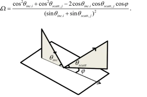
, ,
( inc i, scatt j, )
gθ θ ϕ is a three-dimensional scattering function, that is the plane wave amplitude scattering from per unit area. In the monostatic reverberation calculation, the incident and scattered sound rays are always in a vertical plane. Therefore, the scattering coefficient is only related to the two variables of inci-dent grazing angle θinc i, and scattering grazing angle θscatt j, . For bistatic
re-verberation, the incident sound ray and the scattered sound ray are not in the same vertical plane, we also need to introduce the scattering azimuth angle
ϕ
to describe the scattering function as shown in Figure 1.
Based on the Lambert backscattering model, Ellis and Haller established a three-dimensional scattering model suitable for long-range reverberation. The scattering coefficient is expressed as [3]
(
)
2 2 2,, , , sin , sin , (1 )
inc i scatt j inc i scatt j
g θ θ ϕ µ θ θ υ e σ
−∆Ω
= + + ∆Ω . (3)
The first term in formula (3) is the Lambert scattering coefficient, caused by backscattering. The second term caused by side scattering is presented based on the Kirchhoff approximation and the Helmholtz equation under the assumption that bottom is isotropy and the roughness of the interface is in accordance with the Gaussian distribution. µ is the backscatter intensity,
σ
is the lateral scattering intensity, ∆Ω is a measure of the deflection of the scattered ray fromthe specularly reflected ray given by
2 2
. , . ,
2
. ,
cos cos 2cos cos cos
(sin sin )
inc i scatt j inc i scatt j
inc i scatt j
θ θ θ θ ϕ
θ θ
+ −
∆Ω =
[image:3.595.268.507.553.710.2]+ . (4)
DOI: 10.4236/jamp.2018.611205 2448 Journal of Applied Mathematics and Physics
According to Equation (2), the bottom reverberation intensity received from scatterer of unit area can be expressed as:
2 2
2
, , , ,
1 1 ( ) ( ) ( , , )
N M
scatt inc i i scatt j j inc i scatt j i j
I p r p r gθ θ ϕ
= =
=
∑∑
. (5)Supposing the pulse intensity emitted from the source is I0
( )
τ , and the pulse duration is τ0, the reverberation intensity at time t can be expressed as thesu-perposition of the scattered signals received at that time,
( )
( )
0
0 0
( ) scatt ,
R t =
∫
τ Iτ
I dA tτ
, (6)where arrival time t=
τ
inc i, +τ
scatt j, , τinc i, andτ
scatt j, are the time of ray fromsource to scatterer and from scatterer to receiver, respectively, dA t
( )
,τ is the scattering area. The scattering area is divided into k scattering elements, and the area of the kth element is represented by ∆sk. The reverberation intensityre-ceived by the hydrophone can be expressed as discrete form:
( )
01 K
scatt k k
R t I I s
=
=
∑
∆ .(7) [image:4.595.229.520.562.705.2]
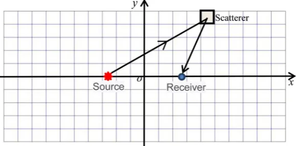
In early literatures, when calculating monostatic bottom reverberation, i.e., source and receiver are in the same horizontal position, the scattering region contributing to reverberation at a certain time is usually regarded as a ring. Si-milarly, for the calculation of bistatic bottom reverberation, the scattered sound waves received by the receiver at the same time are considered to be from the scattering region of an elliptical ring with source and receiver respectively lo-cated at the two focal points of the elliptical ring. This kind of method assumes that rays of different propagation paths reach the same scatterer at the same time when calculating reverberation. However, in the deep-water environment, the ray paths from source to scatterer and from scatterer to receiver are diverse. Meanwhile the propagation time is obviously different. Therefore the area con-tributing to the reverberation at any given moment is not a ring or an elliptical ring. In order to obtain accurate results, we do not use ring or elliptical ring to divide the scatterer. Instead, bottom is divided into grids firstly, i.e. dividing the seabed into a large number of rectangular scatterers as shown in Figure 2.
DOI: 10.4236/jamp.2018.611205 2449 Journal of Applied Mathematics and Physics
In Figure 2, when the divided grids are small enough, we could use one point to represent the entire scattering area on the grid for calculation. The received reverberation signal is obtained through multiplying the calculation result on each scattering element by the scattering area and summation. The finer the mesh is, the more accurate the calculation results will be, but the calculation time will also increase. In order to improve the computational efficiency while ensuring the calculation accuracy, the dividing size of the scatterer is distinguished when meshing. The scatterers close to the source and receiver are finely divided, while the scatterers far away from the source and receiver are sparsely divided.
Scatterers are symmetrical in four quadrants of the coordinate system includ-ing source and receiver. However, the source depth and receiver depth are usually different. In other words, the influence of scatterers on the reverberation result is not completely symmetric with the y coordinate axis, whereas it is symmetric with the x coordinate axis. Therefore, only the scatterers in first and second quadrant are considered in reverberation calculation, and then the cal-culated results are doubled to obtain the final reverberation intensity.
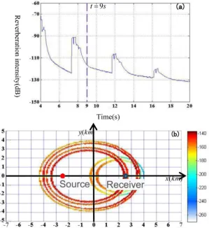
[image:5.595.224.524.356.683.2]For the environment of the experimental area in the South China Sea, Figure 3(a) gives a simulated result of reverberation intensity. The parameters used
DOI: 10.4236/jamp.2018.611205 2450 Journal of Applied Mathematics and Physics
here are: water depth is 3472 m, source frequency is 500 Hz, source depth is 200 m, receiver depth is 3021 m, and the distance between source and receiver is 5 km. The bottom acoustic parameters and scattering coefficient are the same as those given in next section. For the reverberation intensity at 9-s time (see ure 3(a), this moment is between the second and third bottom reflection), Fig-ure 3(b) gives scatterers contribution at different locations on the bottom. One can see that, under this simulation condition (the horizontal positions and depths of source receiver are different), scatterers affecting the reverberation re-sult at this moment is not in the same elliptical ring, but distribute in a number of circles, corresponding to different propagation ways. As the reverberation time increases, the corresponding elliptical ring will continue to expand until the next reverberation peak appears, that is, a new bottom reflection occurs. After that, a new group of elliptical rings will appear corresponding to different prop-agation paths.
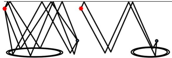
Figure 4 shows the acoustic propagation paths corresponding to different scatterer rings in Figure 3(b). One can see that four elliptical rings close to the sound source correspond to four types of rays: bottom-surface-bottom reflection, bottom-surface reflection, surface-bottom-surface-bottom reflection, and sur-face-bottom-surface reflection. In addition, two elliptical rings near the receiver correspond to two types of acoustic transmission: bottom-surface-bottom reflec-tion, surface-bottom-surface-bottom reflection. The size and position of the el-liptical rings contributing to the reverberation signal is related to the relative po-sition of source and receiver. According to the analysis above, for deep-water environment, there are many transmission paths from the source to receiver, and the conventional method of dividing the bottom scatterers as circular rings or elliptical rings cannot provides reverberation results accurately. In this paper, the scatterers on the bottom are divided into network format in advance, and then the scattering elements are selected according to the actual propagation path and time, which can improve the calculation accuracy.
3. Comparison between Numerical Simulations
and Experimental Results
Using the deep-water bottom reverberation model proposed in Section 2, we cal-culate reverberation intensity for different conditions. In numerical simulations,
[image:6.595.224.518.592.692.2]DOI: 10.4236/jamp.2018.611205 2451 Journal of Applied Mathematics and Physics
we take 3472-m water depth and use the sound velocity profile measured in the experiment conducted in the South China Sea. A single-layer liquid bottom model with semi-infinite space is used. Acoustic parameters in the bottom are as follows: sound velocity is 1580 m/s, density is 1.6 g/cm3, absorption coefficient is
0.3 dB/λ. The bottom characteristics represented by these parameters are
con-sistent with those measured through core sampling during the experiment. The scattering coefficients given in Equation (3) are as follows: 10lgν = −10,
10lgµ= −32, and
(
180 / π σ)
=10.Figure 5 shows the numerical simulation results for 500-Hz source frequency, in which the experimental reverberation intensity is also provided to compare. One can see that reverberation intensity obtained by numerically calculating is in good agreement with the experimental data as a whole. The experimental re-verberation intensity increases obviously at the time of about 27 - 34 s in Figure 5, which is generated by wave reflection from a seamount near the receiving ar-ray.
4. Summary
We present a deep-water bottom reverberation model based on ray theory,
[image:7.595.69.529.354.667.2]DOI: 10.4236/jamp.2018.611205 2452 Journal of Applied Mathematics and Physics
which can calculate both monostatic and bistatic reverberation intensity. In the conventional methods, scattering region contributing to reverberation signal at a certain time is usually treated as a circular ring or an elliptical ring. Different from them, bottom is firstly divided into a number of grids, and then reverbera-tion is calculated on the basis of exact time from each grid to the source and re-ceivers. As a result, this model can calculate deep-water reverberation more ac-curately.
Acknowledgements
This work is supported by the National Natural Science Foundation of China (Grant Nos. 11874061, 11434012, 11474302).
Conflicts of Interest
The authors declare no conflicts of interest regarding the publication of this pa-per.
References
[1] Bucker, H.P. and Morris, H.E. (1968) Normal-Mode Reverberation in Channels or Ducts. Journal of the Acoustical Society of America, 44, 827.
https://doi.org/10.1121/1.1911187
[2] Zhang, R. and Jin, G. (1984) Normal-Mode Theory of Average Reverberation Inten-sity in Shallow Water. Acta Acustica, 119, 215-223.
[3] Ellis, D.D. (1995) A Shallow-Water Normal-Mode Reverberation Model. Journal of the Acoustical Society of America, 97, 2804-2814. https://doi.org/10.1121/1.411910
[4] Collins, M.D. and Evans, R.B. (1998) A Two-Way Parabolic Equation for Acoustic Backscattering in the Ocean. The Journal of the Acoustical Society of America, 91. [5] Mcdaniel, S.T. (1992) Backscattering from Rough Interfaces and the Parabolic
Ap-proximation. Journal of the Acoustical Society of America, 91, 31. https://doi.org/10.1121/1.402625
[6] Weinberg, H. (1982) Generic Sonar Model. Oceans, IEEE, 201-205.
https://doi.org/10.1109/OCEANS.1982.1151943
[7] Lupien, V.H., Bondaryk, J.E. and Baggeroer, A.B. (1995) Acoustical Ray-Tracing Insonification Software Modeling of Reverberation at Selected Sites near the Mid-Atlantic Ridge. Journal of the Acoustical Society of America, 98, 2987-2987. https://doi.org/10.1121/1.413929
[8] Mackenzie, K.V. (1961) Bottom Reverberation for 530- and 1030-cps Sound in Deep Water. Journal of the Acoustical Society of America, 33, 1498-1504.
https://doi.org/10.1121/1.1908482
[9] Urick, R.J. (1962) Backscattering of Explosive Sound from the Deep-Sea Bed.
J.acoust.soc.am, 34. https://doi.org/10.1121/1.1909106