CRO-5500
Redundant RAID
Controller Kit
CMD Technology, Inc. 1 Vanderbilt
Irvine, California 92718 (714) 454-0800
Trademarks and Copyright
CMD, CMD Technology, and CRD-5500 are trademarks of CMD Technology, Inc. All other product and company names are trademarks or registered trademarks of other manufacturers.
Copyright © CMD Technology, Inc. 1996. All rights reserved.
CMD reserves the right to make changes to this manual and the equipment described in this manual without notice. CMD has made all reasonable efforts to ensure that the information in this manual is accurate and complete. CMD will not be liable, however, for any technical or editorial errors or omissions made in this manual, or for incidental, special, or consequential damage of whatsoever nature, resulting from the furnishing of this manual, or operation and performance of equipment in connection with this manual.
FCC Notice
This equipment has been tested and found to comply with the limits of a Class B digital device, pursuant to Part 15 of the FCC rules. These limits are designed to provide reasonable protection against harmful interference in a residential installation. This equipment generates, uses and can radiate radio frequency energy and, if not installed and used in accordance with the instructions, may cause harmful interference to radio communications. However, there is no guarantee that interference will not occur in a particular installation. If this equipment does cause harmful interference to radio or television reception, which can be determined by turning the equipment off and on, the user is encouraged to try to correct the interference by one or more of the following measures:
• Reorient or relocate the receiving antenna.
• Increase the separation between the equipment and receiver.
• Connect the equipment into an outlet on a circuit different from that to which the receiver is connected.
• Consult the dealer or an experienced radiorrV technician for help.
Any changes or modifications not expressly approved by the manufacturer could void the user's authority to operate the equipment.
Statement of License Limitations
CMD is licensed under patents by EMC which contain claims directly applicable to controllers. The purchase of this controller product does not expressly nor impliedly license the purchaser to combine or use the product in combination with any other products or components which combination would be covered by EMC patent claims applicable to RAID subsystems. As used herein, controllers means a single or mUlti-processor device or group of functionally interrelated devices operable to physically and/or logically configure a plurality of physical mass storage devices as one or more independently accessible arrays, and to control the communication of data between the array(s) and host(s) or client(s) in a predetermined RAID format or other formats. RAID subsystems means a storage subsystem including one or more arrays of physical mass storage devices, and one or more controllers associated therewith.
Declaration of Conformity
CMD Technology, Inc. declares that the equipment described in this document is in conformance with the requirements of the European Council Directives listed below:
89/336/EEC 93/68/EEC
EMC Directive EMC Directive
On the approximation of the laws of Member States relating to Electromagnetic Compatibility.
This declaration is based upon compliance of the product to the following standards:
EN 55022, CISPR 22B EN 50082-1 lEC 801
RF Emissions Control
Immunity to Electromagnetic Disturbances
Product Description: RAID SCSI to SCSI Interface CRD-5500
Model:
(E
Manufacturer:
Warranty
CMD Technology, Inc. 1 Vanderbilt
Irvine, California 92718 (USA)
CMD Technology warrants this product to be free of defects in materials and/or workmanship for a period of 3 years from the date of purchase. If the product proves to be defective within the warranty period, CMD Technology will either repair or replace it. This warranty covers defects incurred in normal use only. Defects, malfunctions, or failures resulting from accidents, misuse, or mishandling are not covered. In the event that this product must be repaired or replaced, please contact CMD for an RMA number.
Note
This page left blank intentionally.
CRD-5500 Redundant RAID Controller Kit
1 Introduction
Two CRD-5500s may be combined to form a fault-tolerant system. If either controller detects that the other controller is not functioning properly, it automatically assumes responsibility for all system I/O activity. This switch over occurs automatically and virtually instantly. If you have two CRD-5500 controllers equipped with multiple host channels, you may designate individual host channels as either active or passive, providing a means to balance I/O activity between controllers.
2 Requirements
To combine two CRD-5500s as a redundant pair, both controllers must be configured as follows:
1 Both controllers must be equipped with the 5552 motherboard. Controllers with the 5552 motherboard will have a serial number of 5000 or higher.
2 Both controllers must be running the same firmware revision (8.0 or higher).
3 The amount of cache installed in each controller must be the same.
4 The amount of cache installed in SIMM slots OA and 1 A must equal the amount installed in slots OB and IB, as described in section 3.
5 The same number of SCSI I/O modules must be installed in each controller.
6 The type of I/O module instal1ed in each slot on one controller must be the same as that installed in the corresponding slot on the other controller.
7 Each disk must be connected to the same disk channel on each unit.
8 Corresponding host modules on each controller must also be connected on the same SCSI host busses.
9 The Redundant Controller Communication (RCC) cable must be connected between the two controllers.
10 Each controller must have its own dedicated monitor.
11 Each controller should have a battery connected to it. At least one of the controllers must have a battery connected to it, to protect the cache data in the event of a power failure.
Note
CRD-5500
2
3 SIMM Installation
To utilize the redundant controller capability of a pair of CRD-5500s, both units must have the same amount of SIMM cache installed. Refer to the CRD-5500 User's Manual for information on purchasing SIMMs.
Warning
Be sure to remove all power (including battery power) to the controller before installing SIMMs. Observe all anti-ESD shop practices before you touch a SIMM.
On the 5552 motherboard, slots OA and IA form one set of cache memory. Slots OB and IB form another set. While one set is reading and writing data, the other set is "mirroring" the read/write. In the event of one CRD-5500's failure, one of the two halves of cache memory in the surviving CRD-5500 takes over the failed unit's read/write functions. Refer to Figure 1.
OA 08 1A 18
The SIMMs in these two slots hold another set of cache memory.
[image:6.612.135.537.253.576.2]D
D
Figure 1: Arrangement of SIMM slots on 5552 motherboard
Note
It is not necessary for the SIMM configuration to be congruent as long as the same amount of memory is installed in each slot pair. For example: if a 64MB SIMM is in slot OA, a 32MB SIMM is in slot OB and a 32MB 81 MM is in slot 1 B, the requirements are met even though slot 1 A is empty.
CMD recommends that SIMMs from the same manufacturer be used in anyone CRD-5500.
If you are installing only one SIMM in a slot pair, use slot OA or slot OB as appropriate.
CRD-5500
4 RCC Cable Connection
Warning
Do NOT force the RCC cable connectors into the redundant controller connectors. Serious damage may result.
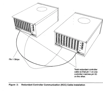
To function in the redundant controller mode, the two identically configured CRD-5500 controllers must be connected together with the specially provided redundant controller communication (RCC) cable. The cable must be twisted so that pin 1 on one controller matches pin 50 on the other controller, as shown in Figure 2.
An 1 Stripe
Twst redLrdcnt cxrtrdler
calje so that pin 1 on one
cxrtroller rratd1es pin 50
onthedher.
[image:7.615.109.545.210.598.2]CRD-5500
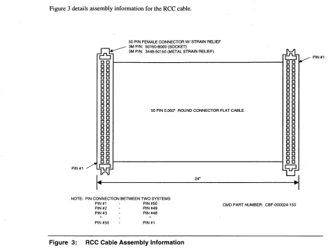
Figure 3 details assembly information for the RCC cable.
50 PIN FEMALE CONNECTOR WI STRAIN RELIEF . - - - - 3M PIN: 50150·BooO (SOCKET)
0-
3M PIN: 3448-50150 (METAL STRAIN RELIEF)ro
PIN #1
DO ~---4 DO
DO DO
DO DO
DO DO
DO DO
DO DO
DO DO
DO DO
DO DO
DO DO
DO DO
DO DO
o 0 50 PIN 0.050" ROUND CONNECTOR FLAT CABLE C 0
DO DO
DO DO
DO DO
DO DO
DO DO
DO DO
DO DO
DO DO
DO DO
DO DO
DO DO
DO DO
DO DO
PIN#1
Q
Q
I~
24".1
NOTE: PIN CONNECTION BETWEEN TWO SYSTEMS
PIN #1 PIN #50 CMD PART NUMBER: CBF-000024-150
PIN #2 PIN #49 PIN #3 PIN #48
PIN #50 PIN#1
Figure 3: RCC Cable Assembly Information
CRD-5500
5 Single-Host Configuration Examples
Note
The following examples are intended to illustrate the general principles of configuring a redundant controller system, and should not be construed to imply that they are the preferred or
recommended method.
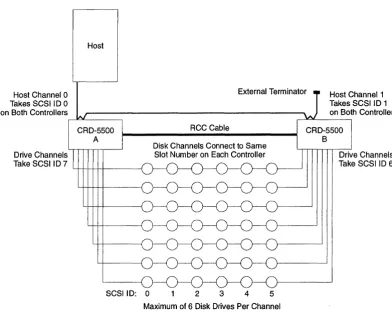
Figure 4 depicts one typical redundant controller configuration with two host channels per controller and a single host. Table I lists host channels, SCSI IDs and status for a typical single-host configuration.
Host Channel 0 Takes SCSI I D 0 on Both Controllers
External Terminator Host Channel 1 Takes SCSI I D 1
Drive Channels
CRD-5500 A
Take SCSI I D 7 L+-l--++++---J
SCSIID: 0
RCC Cable
2 3 4 5
[image:9.615.144.537.255.567.2]Maximum of 6 Disk Drives Per Channel
Figure 4: Single-host cabling diagram (example 1)
Table 1: Example Configuration for Single-Host System
Controller/Host Channel SCSIID Status
AlO 0 Active
Al1 1 Passive
B/O 0 Passive
8/1 1 Active
on Both Controllers
CRD-5500 B
CRO-5500
6
By using Host LUN Mapping, you may balance 110 traffic between controllers by assigning some of your RAID sets to one host channel and the remainder to the other host channel. In the above example, RAID sets mapped to host channel 0 would be handled by controller A. RAID sets mapped to host channel 1 would be handled by controller B.
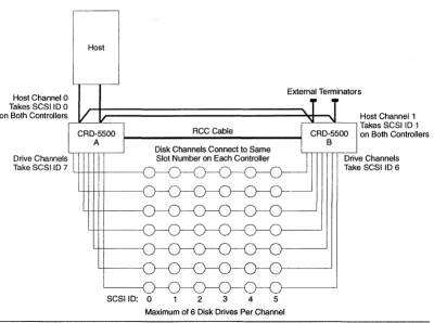
Figure 5 depicts another typical redundant controller configuration. This configuration offers greater throughput than the one shown in Figure 4. Host channels, SCSI IDs and status for this configuration are the same as in Table 1.
Host Channel 0 Takes SCSIID 0 on Both Controllers
Drive Channels
Host
Take SCS I I D 7 4-!1-+-i-t-t---{
SCSIID: 0 2 3 4 5
External Terminators
Host Channel 1 ,---'L----'L---, Takes SCSIID 1
on Both Controllers
[image:10.613.146.546.184.482.2]Maximum of 6 Disk Drives Per Channel
Figure 5: Single-host cabling diagram (example 2)
One host SCSI bus runs to host channel 0 on controller A, then to host channel 0 on controller B. The other host SCSI bus runs to host channel 1 on controller A, then to host channel 1 on controller B. Both hosts are then terminated with external terminators (the other end of each bus is terminated at the host adapter).
CRO-5500
6 Multiple-Host Configuration Examples
Note
These examples are intended to illustrate the general principles of configuring a redundant controller system, and should not be construed to imply that they are the preferred or
recommended methods. There are many ways to configure such a redundant controller system. For instance, many users will wish to run disk channel cables from one controller to the other and then to the disk drives.
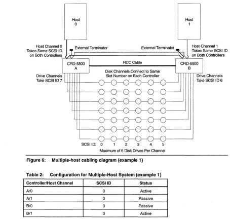
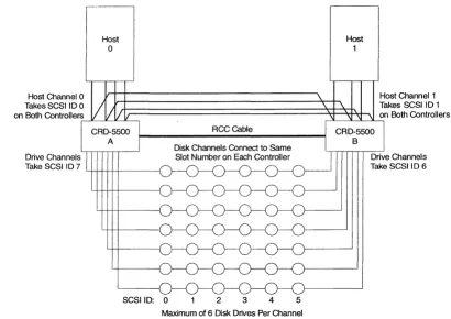
In the configuration diagrammed in Figure 6, both CRD-5500 controllers have two host channels. Host computer 0 is connected to host channel 0 on both controllers, and host computer I is connected to host channel I on both controllers. By using the host channel status settings listed in Table 2, and by using host LUN mapping to map RAID sets to particular host channels, you may isolate JlO activity for host computer 0 on controller A and JlO activity for host computer 1 on controller B, while still benefiting from redundancy.
Host
o
Host 1Host Channel 0 _ External Terminator External Terminator
Takes Same SCSIID T r--~'-~-~-~---~~----""""';~
Host Channel 1 Takes Same SCSI ID on Both Controllers on Both Controllers
RCCCable
Drive Channels
Take SCSI ID 7 L+-l--++++---f
SCSIID: 0 2 3 4
[image:11.613.96.550.291.725.2]Maximum of 6 Disk Drives Per Channel
Figure 6: Multiple-host cabling diagram (example 1)
Table 2: Configuration for Multiple-Host System (example 1)
Controller/Host Channel SCSI 10 Status
NO 0 Active
N1 0 Passive
B/O 0 Passive
B/1 0 Active
CRD-5500 B
CRD-5500
In the configuration diagrammed in Figure 7, both CRD-5500 controllers have four host channels. Host computer 0 is connected to host channels 0 and 1 on both controllers, and host computer 1 is connected to host channels 2 and 3 on both controllers. This configuration offers greater throughput than the one shown in Figure 6. By using the host channel status settings listed in Table 3, and by using host LUN mapping to map RAID sets to particular host channels, you may isolate 110 activity for host computer 0 on controller A and I/O activity for host computer 1 on controller B, while still benefiting from redundancy.
R
II
...
i
External Terminators External TerminatorsHost 1
CRD-5500 A
RCC Cable CRD-5500
Drive Channels Take SCSI 107
SCSI 10: 0 2 3 4 5
[image:12.612.86.554.149.746.2]Maximum of 6 Disk Drives Per Channel
Figure 7: Multiple-host cabling diagram (example 2)
Table 3: Configuration for Multiple-Host System (example 2)
Controller/Host Channel SCSIID Status
AlO 0 Active
Al1 1 Passive
Al2 2 Active
Al3 3 Passive
B/O 0 Passive
B/1 1 Active
8/2 2 Passive
B/3 3 Active
8
Drive Channels Take SCSI 10 6
[image:12.612.128.538.167.494.2]CRD-5500
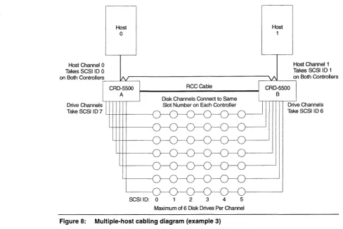
The configuration diagrammed in Figure 8 supports a dual-ported host environment (e.g., YMS/AXP SCSI cluster, Windows NT cluster, TruCluster for DEC UNIX). It requires only one SCSI cable and one SCSI controller per host system. Host channels, SCSI IDs and status for this configuration are shown in Table 4.
' - l
Host
a
Host
1
Host Channel 1 Takes SCSI 10 1 on Both Controllers
~-->L-"-_~
RCCCabie
Drive Channels
Take SCSI ID 7 4-+-++++---j
SCSIID:
a
2 3 4 5 [image:13.613.42.550.110.742.2]Maximum of 6 Disk Drives Per Channel
Figure 8: Multiple-host cabling diagram (example 3)
Table 4: Configuration for Multiple-Host System (example 3)
Controller/Host Channel SCSIID Status
Ala 0 Active
Al1 1 Passive
B/O 0 Passive
[image:13.613.65.553.118.443.2]CRD-5500
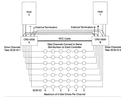
The configuration diagrammed in Figure 9 also supports a dual-ported host environment (e.g., VMSIAXP
SCSI cluster, Windows NT cluster, TruCluster for DEC UNIX). Because it uses two SCSI cables, it has greater throughput than the configuration shown in Figure 8. Host channels, SCSI IDs and status for this configuration are shown in Table 5.
Host Channel 0 Takes SCSI ID 0
Host
o
on Both Controllers~--'L-IL_~
Drive Channels
Take SCSIID7 LI-l-H---I--+---f
SCSIID: 0
RCCCable
2 3 4 5
[image:14.613.83.544.125.734.2]Maximum of 6 Disk Drives Per Channel
Figure 9: Multiple-host cabling diagram (example 4)
Table 5: Configuration for Multiple-Host System (example 4)
Controller/Host Channel SCSIID Status
AlO 0 Active
Al1 0 Passive
B/O 0 Passive
B/1 0 Active
Host
1
Host Channel 1 Takes SCSI ID 1 on Both Controllers
, - - - ' - - - ' - - - ,
[image:14.613.134.537.127.418.2]CRO-5500
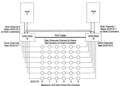
The configuration diagrammed in Figure 10 also supports a dual-ported host environment (e.g., VMS/AXP SCSI cluster, Windows NT cluster, TruCluster for DEC UNIX). Because it uses four SCSI cables, it has greater throughput than the configuration shown in Figure 9. Host channels, SCSI IDs and status for this configuration are shown in Table 6.
Host
o
Host Channel 0 Host Channel 1
Takes SCSI ID 0 Takes SCSI ID 1
on Both Controllers .---I'---"---'''----''~
rt;:=================::s;+=~~~
I
on Both ControllersDrive Channels Take SCSIID 7
RCCGable
SCSIID: 0 2 3 4 5
[image:15.613.73.568.106.762.2]Maximum of 6 Disk Drives Per Channel
Figure 10: Multiple-host cabling diagram (example 5)
Table 6: Configuration for Multiple-Host System (example 5)
Controller/Host Channel SCSIID Status
AlO 0 Active
Al1 0 Passive
Al2 0 Active
Al3 0 Passive
B/O 0 Passive
B/1 0 Active
B/2 0 Passive
[image:15.613.141.551.132.422.2]CRD-5500
12
7 Configuring the Redundant Controller Mode
After setting the hardware up as described above, the two controllers can be powered on. After running self test, they will automatically attempt to bind themselves into a redundant controller set. The first attempt will normally fail because various setup parameters first need to be configured.
Note
The following screens depict a configuration example for one controller in a redundant pair. Unless otherwise directed, you must perform each step on the other controller as well.
1 Go to the MAIN MENU and select Setup Parameters.
Right Raid Unit Monitor Utility MAIN MENU
+---+
RAID Set Information I Setup Parameters
+---+
Host Parameters System Parameters Host LUN Mapping Disk Parameters Channel Settings Rdnt Ctrlr Parameters
07-29-96 15:32:48
UP ARROW: CURSOR UP I DOWN ARROW: CURSOR DOWN I ENTER: SELECT I CTRL-Z: EXIT I
2 Select Rdnt Ctrlr Parameters (Redundant Controller Parameters). The following screen will appear:
Right Raid Unit Monitor Utility REDUNDANT CONTROLLER PARAMETERS
+- - - -- - --- ---- - - -- -+--- ---+
I Parameter I Value I
+---+---+
I
Controller Name
I
# 1 Host I/O Channel 0 Active Host I/O Channel 1 PassiveARROW KEYS: MOVE CURSOR I ENTER: SELECT I CTRL-Z: EXIT I
3 Perform the following actions:
07-29-96 15:39:26
A Enter a name or number for each controller. This name will be used in other screens to identify the controller. It is a good idea to select a descriptive name to help you distinguish between the controllers. Names reflecting the physical location of the controller, such as "Top," "Bottom," "Left," or "Right," may be helpful.
B Set the status for each of the host 110 channels. When you restart the controllers to complete the configuration, the host channel status settings on the second controller to finish booting up will automatically be the opposite of the settings on the first controller. In other words, if the first controller boots up with host channel 0 as active and host channell as passive, then the second controller will automatically set its host channel 0 as passive and host channel 1 as active.
When finished, press CTRL-Z to return to the MAIN MENU.
CRD-5500
4 Select Setup Parameters.
Right Raid Unit Monitor Utility MAIN MENU
+---+
RAID Set Information
I
Setup Parameters+---+
Host Parameters System Parameters Host LUN Mapping Disk Parameters Channel Settings Rdnt Ctrlr Parameters
+---+
07-29-96 15:40:28
UP ARROW: CURSOR UP I DOWN ARROW: CURSOR DOWN I ENTER: SELECT I CTRL-Z: EXIT I
5 Select Disk Parameters.
Right Raid Unit Monitor Utility DISK PARAMETERS
+---+---+---+ I Channel I Termination I Module Description
+---+---+---+
I
2I
FullI
l6-Bit Single-EndedI
3 Full l6-Bit Single-Ended
+---+
ARROW KEYS: MOVE CURSOR I ENTER: SELECT I CTRL-Z: EXIT I
6 Select the proper SCSI termination for each disk channel.
07-29-96 15:43:10
A If the relevant controller is at the end of the SCSI bus, set termination to FULL, unless you are using external terminators on the disk channel buses.
B If the relevant controller is in the middle of the SCSI bus, set termination to OFF.
C If you are using 16-bit "wide" SCSI modules, you may also select PARTIAL termination. In which case, the module will terminate the upper 8 bits of the bus only. Use this option if you are mixing wide and narrow drives on the same bus, and the I/O module is in between a wide drive and a narrow drive.
When finished, press CTRL-Z to return to the MAIN MENU.
NOTE
The above applies only for the 5540 fast/wide single-ended module. For the 5560
CRD-5500
14
7 Select Setup Parameters.
Right Raid Unit Monitor Utility MAIN MENU
+---+
RAID Set Information
I
Setup Parameters+---+
Host Parameters System Parameters Host LUN Mapping Disk Parameters Channel Settings Rdnt Ctrlr Parameters
+---+
07-29-96 15:44:02
UP ARROW: CURSOR UP I DOWN ARROW: CURSOR DOWN I ENTER: SELECT I CTRL-Z: EXIT I
8 Select Host Parameters.
Right Raid Unit Monitor Utility HOST PARAMETERS
+---+---+---+ ! Parameter I Channel 0 I Channel 1 I
+---+---+---+
SCSI ID Tag Queuing Sync. Mode Sync. Rate Bus Width Termination
ON ON 20 MB/SEC 16 Bit FULL
1 ON ON 20 MB/SEC 16 Bit FULL
ARROW KEYS: MOVE CURSOR I ENTER: SELECT I CTRL-Z: EXIT I
NOTE
07-29-96 15:51:17
The controller will not let you configure a passive host module.
9 Configure each active host module as required. Each host channel configuration must dovetail with its counterpart on the other controller. When two controllers boot up and attempt to form a redundant pair, the first controller to boot up will identify its active host channels and instruct the other controller to configure its counterpart host channels to match those on the first. Similarly, when the second controller boots up, it will copy the configuration information for its active host channels to the other controller. When finished, press CTRL-Z to return to the MAIN MENU.
10 Select Setup Parameters.
Right Raid Unit Monitor Utility MAIN MENU
+---+
RAID Set Information
I
Setup Parameters+---+
Host Parameters System Parameters Host LUN Mapping . Disk Parameters
Channel Settings Rdnt Ctrlr Parameters
+---+
07-29-96 15: 44: 02
UP ARROW: CURSOR UP I DOWN ARROW: CURSOR DOWN I ENTER: SELECT I CTRL-Z: EXIT I
CRD-5500
11 Select Host LUN Mapping.
Right Raid Unit Monitor Utility HOST LUN MAPPING
07-29-96 15:46:22
Channel 0
+-- - - --+- --- -- - - -- ---+ I Host LUN I Redundancy Group I
+---+---+ o 1 2 3 4 5 6 7 8 9 10 11 12 13 14 15 +---+ + - - - -+ - --- -- - - - --- - - ----+ I Host LUN I Redundancy Group I
+---+---+
16 17 18 19 20 21 22 23 24 25 26 27 28 29 30 31+---+
N: NEXT CH I P: PREY CH I eNTER; SELECT I C: CLEAR I D: DEFAULT I CTRL-Z: EXIT
12 If you have more than one host channel in each controller, you may balance I/O activity between each controller with the Host LUN Mapping screen. Select an active host channel with the Nand P keys. (The controller will not let you set LUN mapping for a passive channel.) Use the C key to clear the screen if you wish to start with a blank slate. Then, match the redundancy groups that you wish this host channel to handle to a logical unit number (LUN). This is the LUN that the host will use to address the redundancy group. A dash (-) indicates that the LUN is not mapped to any redundancy group.
When you have finished with one active host channel, switch to the other controller's Host LUN Mapping screen, select an active host channel, and assign LUNs to other redundancy groups not mapped to the other controller's active host channel or channels. For example, you might map redundancy groups 4 through 7 to LUNs 0 through 3 on host channell ofthe second controller, as follows.
Left Raid Unit Monitor Utility HOST LUN MAPPING
Channell
07-29-96 15:46:22
+---+---+
+---+---+
I Host LUN I Redundancy Group I+---+---+ o 1 2 3 4 5 6 7 8 9 10 11 12 13 14 15
I Host LUN I Redundancy Group I
+---+---+
16 17 18 19 20 21 22 23 24 25 26 27 28 29 30 31N: NEXT CH I P: PREY CH I ENTER: SELECT I C: CLEAR I D: DEFAULT I CTRL-Z: EXIT
In this example, the host would access redundancy groups 0 through 3 through host channel 0 of the "Right Raid"controller and redundancy groups 4 through 7 through host channel 1 of the "Left Raid" controller.
When finished, press CTRL-Z to return to the MAIN MENU.
CRO-5500
16
14 Select Setup Parameters.
Right Raid Unit Monitor Utility MAIN MENU
+---+
RAID Set Information
I
Setup Parameters+---+
Host Parameters System Parameters Host LUN Mapping Disk Parameters Channel Settings
+- Rdnt Ctr1r Parameters
+---+
07-29-96 15:47:01
UP ARROW: CURSOR UP I DOWN ARROW: CURSOR DOWN I ENTER: SELECT I CTRL-Z: EXIT I
15 Select Rdnt Ctrlr Parameters.
Right Raid Unit Monitor Utility REDUNDANT CONTROLLER PARAMETERS
+---+---+ I Parameter I Value I
+---+---+
I
Controller Name 11
I
Host I/O Channel 0 Active Host I/o. Channel 1 Passive+---+
ARROW KEYS: MOVE CURSOR I ENTER: SELECT I CTRL-Z: EXIT I
07-29-96 15:47:07
16 Verify the parameters on both monitors. If they are in order, press CTRL-Z to return to the MAIN MENU.
17 Select System Information.
Right Raid Unit Monitor Utility MAIN MENU
+---+
RAID Set InformationI
Setup Parameters System Information+---+
I/O Statistics Free Lists Statistics Manufacturing Information Environmental Status I/O Process Information Rdnt Ctr1r Information
+---+
07-29-96 15:47:16
UP ARROW: CURSOR UP I DOWN ARROW: CURSOR DOWN I ENTER: SELECT I CTRL-Z: EXIT I
18 Select Rdnt etr/r Information.
Right Raid Unit Monitor Utility REDUNDANT CONTROLLER INFORMATION
07-29-96 15:48:20
+---+---+---+
I Controller Name I LEFT I RIGHT I
+---+---+---+
I Disk Channel ID I 6 I 7 I
+---+---+---+
I Host I/O Channel I 1 I 0 I
+---+---+---+
I
Active RAID Set
I
4 5 6 7I
0 1 2 3I
Numbers+---+---+---+ I Last Msg Sent I Heartbeat Count: 45 (Ch 1) I Heartbeat Count: 45 (Ch 1) I
---+ +---+---+
I
Status
I
Bind Successfully Completed: 07-29-96 15:26:00I
+---+
CTRL-Z: EXIT I
CRD-5500
19 Verify the following:
A The' STATUS indicates that the bind was successfully completed.
B The disk channel IDs and host I/O channels are separate and distinct for each controller.
C Active RAID set numbers are not duplicated between the two controllers.
o
Heartbeat messages are being sent and recei ved between the two controllers.This concludes the configuration procedure for redundant controller mode operation.
8 Restart After Switchover
NOTE
To avoid disrupting SCSI bus activity when replacing a failed CRO-5500 unit in a redundant controller configuration, both units MUST use external termination for both the host and disk channels.
1 Pause or stop all host 110 activity to the CRD-5500 redundant controller subsystem.
2 Shut down the surviving CRD-5500 controller (either from the main menu or the front panel). This is especially important, to ensure that data in the cache is written to disk. IF THIS STEP IS NOT PERFORMED AND THE BATTERY IS REMOVED, ALL DATA IN THE CACHE WILL BE LOST.
3 Power off both CRD-5500 controllers.
4 Remove battery power to both CRD-5500 controllers. Ensure that enough time is allowed for the cache memory to fully discharge before continuing.
NOTE
If a failed CRO-5500 is only being "power-cycled", perform steps 1 through 4. Then skip to steps 10 through 14.
5 Swap the failed CRD-5500 with another identical controller. The unit being swapped in must be configured in exactly the same way (same number and type of host and disk channel modules, same amount of cache memory etc.).
6 Re-establish the system: reconnect terminations, battery power connections, SCSI cables and the RCC cable.
7 Power on both CRD-5500 controllers.
8 Reconfigure all controller parameters on the replacement unit for each sub-menu choice under Setup
Parameters (i.e., Host Parameters, System Parameters, Host LUN Mapping, Disk Parameters, Channel Settings and Redundant Controller Parameters).
9 Shut down both CRD-5500 controllers (either from the main menu or the front panel).
10 Power cycle both CRD-5500 controllers.
CRD-5500
18
12 Verify that all controller parameters are correct on both units by checking each sub-menu choice under
Setup Parameters (i.e., Host Parameters, System Parameters, Host LUN Mapping, Disk Parameters, Channel Settings and Redundant Controller Parameters).
13 Go to the Redundant Controller Information screen. Verify that the two CRD-5500 controllers have successfully bound. Ensure that all RAID sets are active on the host channels of the correct controller (in accordance with the Host LUN Mapping and Redundant Controller Parameters settings on both controllers ).
14 Resume host 1/0 activity to the CRD-5500 redundant controller subsystem.
CRD-5500