© 2019, IRJET | Impact Factor value: 7.211 | ISO 9001:2008 Certified Journal
| Page 7252
Material Optimization of Wheel Hub using Finite Element Analysis
Sangram B. Kokate
1, Gururaj R. Kulkarni
21
Mtech Mech.CAD/CAM/CAE student pursuing at KIT’s of Engineering Kolhapur, India
2Asst.Professor, Department of Mechanical Engineering KIT’s of Engineering Kolhapur, India
---***---Abstract -
The paper covers the study and analysis of the Mahindra wheel hub using Finite Element analysis (FEA). The current automotive industry trends towards speed acceleration of vehicle by optimizing the weight with maintaining same strength. We studied various researches done so far in weight optimization. Our aim is to reduce the weight of the wheel hub by material optimization. We analyzed various grades of materials viz. aluminum alloys in comparison with the current material. Aluminum with grade 7075 A6 found to be the best alternative for the current material. Using FEA we proved that new wheel hub is light in weight and can sustain same load carrying capacity along with the strength of hub. We also focused on fatigue analysis of wheel hub to find of the life of the wheel hub.Key Words: ANSYS, CATIA, FEA, Fatigue, Optimization, Unsprung, Prototype.
1. INTRODUCTION
Wheel hub & upright assembly is the important part of vehicle suspension system. Allows the steering arm to turn the front wheels Support the vertical weight of the vehicle The purpose of a wheel hub is to attach a wheel to a motor shaft.
The wheel is attached through fasteners to hub due to a good strength The force exerted on hub and upright assembly are of the cyclic nature as the steering arm turned Subjected to fatigue, cornering force, braking force, bump, impact load and combination of all forces due to bump and cornering process, whereas it is subjected to shock load due to excessive vibrations in the hub and upright in off road conditions. The hub must be capable of rigidly supporting its share of the robot’s weight without failure during its expected life span. If the hub geometry and material selection are inadequate, the hub can break completely or bend so much that the motor cannot effectively accomplish its task.
1.1
Construction and Function of Wheel Hubs
The wheel hub acts as a mounting assembly for the wheels of a vehicle. It is a simple structure made of metal that has metal studs on its surface. The hub houses the wheel bearing and supports the lugs. The wheel bearings assist the wheels in turning smoothly. The wheel hub is also attached to the brake rotor. Basically, the function of the wheel hub is to
keep the wheel spinning freely on the bearing while keeping it attached to the vehicle.
1.2 Causes of Defective Wheel Hubs
In most cases, it is not the wheel hub that actually turns bad. The bearings in the hub usually go bad due to age and accumulation of debris. A common symptom of bad wheel bearings is when your vehicle lists to one side while driving. As the wheel hub actually keeps your wheels intact, any fault in the hub and its associated components will result in wandering wheels and irregular wear on your tires. While rounding a sharp turn, if you hear a whirring or squealing noise from the wheel, it is likely that your wheel hub needs attention. As the ABS sensor is a part of your hub, it can also fail and light up the ABS sensor indicator in your vehicle's dashboard.
1.3 Significance of the Right Installation
The wheel hub is the only part that actually holds the wheels to the car, so it is very important that special attention be paid when these parts are being installed. When you take the wheels off your car, the first visible thing will be the wheel hub.
The wheel hub is a part that can easily be installed by a mechanically-inclined person. During installation, the wheel hub needs to be torqued to the specified values. Most manufacturers will void the warranty of the part if it goes defective due to any problems sustained because of improper installation. So, have your owner's manual at hand when you replace the wheel hubs. While you are looking for replacement wheel hubs, be aware that the configurations of ABS included in wheel hubs are different in various vehicles. So, choose the right replacement accordingly.
So we come to know that the wheel hub is key co
mponent in the suspension assembly and undergoes various fluctuating loads so the design and analysis plays vital role in the automotive industry.
2. PROBLEM DEFINITION
© 2019, IRJET | Impact Factor value: 7.211 | ISO 9001:2008 Certified Journal
| Page 7253
2.1 Drawbacks
1) The wheels hubs were very heavy
2) Cracks initiated in wheel hubs leading to failure. 3) Fatigue life of the wheel hub is not defined we don’t
know when the current hubs will break, because that pieces need support a number of cycles.
3. OBJECTIVE
1. To reduce the weight of hub by changing material like Al Alloys grades, mild steel & increase the load carrying capacity along with the strength of hub 2. Analysis of new hub in different material from
present hub.
3. To find von-misses stress on hub due to loading. 4. To find the principle stress of newly designed hub
and compare it with analysis.
5. Manufacturing of new hub in different material from present hub after comparing FEA results. 6. Test the fabricated model on UTM machine. 7. Select the best result and produce newly designed
hub.
4. LITERATURE REVIEW
Study about the stress-strain distribution, fatigue and vibration characteristics of the hub and upright assembly using Finite Element Methods (FEM) by most researchers. Suhaimi et al, through static analysis some parts of upright were eliminated maintaining permissible structural strength through stages such as designing, analysis, fabrication and fitting and 55.82 percent of weight reduction was achieved Tagade et al, extended the scope of static analysis of previous researchers. In analysis geometric modelling was done on CREO 2.0 and ANSYS. The analysis concluded with mass reduction of knuckle by 67% maintaining factory of safety between 3 to 4. Cast iron which is recently using and aluminium alloy which is suggested material.
Dyapa and Shenoy et al carried out modal analysis using unsprung mass, to improve the dynamics of the vehicle. They concluded that the steel upright can definitely replace aluminium without affecting the performance and making the cars very economical.
Razak et al, carried out analysis for lightweight and optimized design of steering knuckle using aluminium 6061-t5 alloy (yield strength 276mpa).that conclude alloy to be best material for the component due to better physical and mechanical properties.
Kulkarni and Tambe et al, developed Finite Element Model in HyperWorks and the Model was solved using RADIOSS solver. OptiStruct solver was used for performing topology optimization to minimize the amount of material to be used and setting geometric parameters as design variables. They reduced the mass of the existing steering knuckle to 53.33%.
5. METHODOLOGY
1) Background Research: Finding out the work done on hub material optimization and understanding the key areas of research done so far.
2) Collection of Data: After the research background study we will collect the useful information we can implement in our project work.
3) Design of hub on Design software: For analysis purpose we have to do design. We are doing the design in Catia V5 and build a 3D model of hub for performing FEA.
4) Analysis of hub on Ansys (workbench19): For analysis we use Ansys Workbench 19 software in this software we are doing static structural analysis for determining Von Mises stress, principle stress, compressive stress, tensile stress, total deformation and energy abortion capacity for different material in analysis.
5) Testing and analysis for a practical result we are testing the material on UTM and impact machine and find out the value like Von Mises stress, principle stress, compressive stress, tensile stress for different material on testing specimen. And compare it with the FEA results and select the best material.
6) Develop Prototype of model for a demonstration purpose we are developing the prototype model of material having better theoretical and practical result.
6. DETAILS ABOUT OUR MATERIAL: ALUMINIUM
ALLOY 7075-T6
Aluminium alloy 7075 is an aluminium alloy, with zinc as the primary alloying element. It is strong, with strength comparable to many steels, and has good fatigue strength and average machinability, but has less resistance to corrosion than many other Al alloys. Its relatively high cost limits its use to applications where cheaper alloys are not suitable. 7075 aluminium alloy's composition roughly includes: 5.6–6.1% zinc, 2.1–2.5% magnesium, 1.2–1.6% copper, and less than half a percent of silicon, iron, manganese, titanium, chromium, and other metals.
© 2019, IRJET | Impact Factor value: 7.211 | ISO 9001:2008 Certified Journal
| Page 7254
7. ANALYSIS OF HUB USING FEA
1. Process involves importing existing geometry (stp), setting up the finite element model, solving, and reviewing results.
2. We have used FEA (Finite Element Analysis) for linear static structural analysis of a hub component. 3. FEA includes meshing technique in which complex
geometry (problem) is divided into small elements for precise results.
4. The basic idea of FEA to make calculation at only limited (Finite) number of points and then interpolate the results for the entire domain (surface or volume).
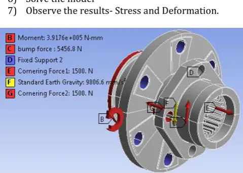
[image:3.595.319.559.475.646.2]5. In the first was necessary to apply some constants forces to obtain some results: equivalent stress, security factor, total deformation
Table 1. Loading Conditions
Standard Earth Gravity
acceleration 9806.6 mm/s
2
Breaking Torque 473.33N-m
Bump Force 3g = 5456.81 N
Cornering force 1500 N
7.1 Braking Torque:
Brake pedal force:
1. The force applied on the pedal is assumed to be 300 N (30.6kgf)
2. Pedal ratio = 6:1
3. fmax= force* pedal ratio = 300 * 6
= 1800 N
(fmax= force applied onto the master cylinder) Hence, P = fmax/ (π/4) * d2
(P =hydrostatic pressure,
d = diameter of master cylinder’s piston) Fmax = (P * π/4) * D2…..[by Pascal's Law] (Fmax = force acting on each piston of the caliper, D = diameter of the piston in the caliper)
By solving,
4. Fmax = fmax * (D/d)2 = (1800)*(.003 / .019)2 = 4487.5346 N
5. Torque acting on the disc:
T = Fmax * μ * Re * number of pistons per calliper = 4487.5346* 0.3 * 0.097 * 3
= 391.76 N-m Where,
μ = Coefficient of friction between brake pad and disc (0.3) Re = effective radius of the disc (97mm).
7.2 Bump Force
The vertical load acting at contact of road and tire, when vehicle comes across bump, is taken as gravitational acceleration. This force is transmitted to hub center and given by:
From Newton’s second law of motion: Fw = Fst *3* g
Fw =5456.8125 N
7.3 Cornering force
When a car is in a steady state turn with constant speed on banking, the load is transferred from the inside to the outside pair of wheels. The cornering force which results from the speed V, the radius of the bend R and the total weight of the vehicle is:
Fc= m*v2/R = 1500.5 N
7.4 Hub Analysis Steps
1) Import the CAD model in Ansys Workbench using Import command.
2) Apply material to the imported geometry
3) Mesh the CAD model with proper meshing techniques.
4) Apply the boundary conditions at the desired locations- fixed support and loading
5) Select result tools such von mises, principal, shear stress and fatigue.
6) Solve the model
7) Observe the results- Stress and Deformation.
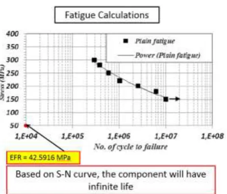
Fatigue 1. FEA Loading Conditions
© 2019, IRJET | Impact Factor value: 7.211 | ISO 9001:2008 Certified Journal
| Page 7255
Fig. 2 Calculation of effective alternating stressFig. 3 Fatigue life using effective alternating stress
[image:4.595.52.275.307.497.2]7.5
FEA Results Summary
Table 2 Comparison chart for FEA analysis of all materials
# Results M.S. Aluminum (6061-T6) Aluminum (7075-T6)
For honeycomb structure
1 Density 7.87 g/cc 2.7 g/cc 2.81 g/cc
2 Compressive Yield Strength 370 Mpa 276 Mpa 503 Mpa
3 Tensile Yield Strength 370 Mpa 276 Mpa 503 Mpa
4 Tensile Ultimate Strength 440 Mpa 310 Mpa 572 Mpa
5 Young's Modulus 205 Gpa 68.9 Gpa 71.7 Gpa 6 Poisson's Ratio 0.29 0.33 0.33 7 Bulk Modulus 1.67E+05 69608 69608
8 Shear Modulus 7.69E+05 26692 26692 9 Safety factor 1.9271 1.7617 1.9499 10 Life 1.e+006 cycles 1.e+008 cycles 1.e+008 cycles
11 Total Deformation 0.00901 mm 0.027472 mm 0.026399 mm
12 Equivalent stress 74.806 Mpa 74.143 Mpa 74.142 Mpa
13 Maximum Principle stress 85.789 Mpa 86.381 Mpa 86.379 Mpa
14 Maximum shear stress 41.976 Mpa 42.011 Mpa 42.01 Mpa
15 Equivalent alternating stress
40.878
Mpa 42.107 Mpa 39.64 Mpa
16 Strain Energy 0.01465 mJ 0.04351 mJ 0.041815 mJ
Looking at the above FEA comparison chart we can clearly say following things,
Density of the aluminum is around one third to that of mild steel so our idea of reducing in weight is achieved. Aluminum 6061 is slightly less as compared to 7075.
Tensile/compressive yield strength of the 7075 is much more than that of the remaining two materials so our choice of the material against the strength is fair.
Safety factor is nearly same for both MS and 7075 materials but it is less for 6061.We can say our new material 7075 work for same load/stress.
The life of aluminum is much greater than that of the steel.
The deformation/displacement is more for aluminum as compared to steel.
Equivalent von-mises stress to 7075 is same or slightly so it can withstand same load.
Equivalent alternating stress is less so it can withstand more load as compared to two
8. MANUFACTURING
Before the design of the hubs can commence it is necessary to choose how it will be manufactured and from what material, since this is fundamental to the design concept. The hub’s main duty is to prevent excessive deflections, particularly in bending. In torsion, which is mainly experienced during braking, excessive deflections can cause excessive fatigue in the hub as well as other components
8.1 Factors Determining the Selection of Materials
[image:4.595.35.295.574.793.2]© 2019, IRJET | Impact Factor value: 7.211 | ISO 9001:2008 Certified Journal
| Page 7256
1. Properties: The material selected must possess thenecessary properties for the proposed application. The various requirements to be satisfied can be weight, surface finish, rigidity, ability to withstand environmental attack from chemicals, service life, reliability etc.
The following four types of principle properties of materials decisively affect their selection
Physical
Mechanical
From manufacturing point of view
Chemical
The various physical properties concerned are melting point, thermal Conductivity, specific heat, coefficient of thermal expansion, specific gravity, electrical conductivity, magnetic purposes etc. The various Mechanical Properties Concerned are strength in tensile, Compressive shear, bending, torsion and buckling load, fatigue resistance, impact resistance, elastic limit, endurance limit, and modulus of elasticity, hardness, wear resistance and sliding properties. The various properties concerned from the manufacturing point of view are:
Cast ability
Weld ability
Surface properties
Shrinkage
Deep drawing etc.
2. Manufacturing Cost: Sometimes the demand for lowest possible manufacturing cost or surface qualities obtainable by the application of suitable coating substances may demand the use of special materials.
3. Quality Required: This generally affects the manufacturing process and ultimately the material. For example, it would never be desirable to go casting of a less number of components which can be fabricated much more economically by welding or hand forging the steel.
4. Availability of Material: Some materials may be scarce or in short supply, it then becomes obligatory for the designer to use some other material which though may not be a perfect substitute for the material designed. The delivery of materials and the delivery date of product should also be kept in mind.
5. Space Consideration: Sometimes high strength materials have to be selected because the forces involved are high and space limitations are there.
8.2 Material Cost Estimation
Material cost estimation gives the total amount required to collect the raw material which has to be processed or
fabricated to desired size and functioning of the components. These materials are divided into two categories.
1) Material for fabrication: In this the material in obtained in raw condition and is manufactured or processed to finished size for proper functioning of the component.
2) Standard purchased parts: This includes the parts which was readily available in the market. A list is forecast by the estimation stating the quality, size and Standard parts, the weight of raw material and cost per kg. For the fabricated parts.
8.3 Procedure for Calculation of Material Cost
The general procedure for calculation of material cost estimation is after designing a project,
1) A bill of material is prepared which is divided into two categories.
Fabricated components
Standard purchased components
2) The rates of all standard items are taken and added up.
3) Cost of raw material purchased taken and added up.
8.4 Machining Cost Estimation
This cost estimation is an attempt to forecast the total expenses that may include manufacturing apart from material cost. Cost estimation of manufactured parts can be considered as judgment on and after careful consideration which includes labour, material and factory services required to produce the required part.
Finally product is manufactured using turning, drilling, milling, grinding machine.
[image:5.595.315.563.576.784.2]8.5 Old vs optimized hub comparison
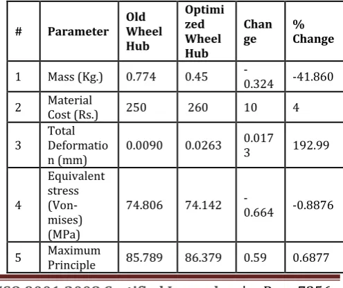
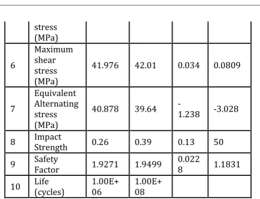
Table 3 Comparison chart for old vs optimized hub
# Parameter Old Wheel Hub
Optimi zed Wheel Hub
Chan
ge % Change
1 Mass (Kg.) 0.774 0.45 -0.324 -41.860
2 Material Cost (Rs.) 250 260 10 4
3 Total Deformatio
n (mm) 0.0090 0.0263
0.017
3 192.99
4
Equivalent stress (Von-mises) (MPa)
74.806 74.142 -0.664 -0.8876
© 2019, IRJET | Impact Factor value: 7.211 | ISO 9001:2008 Certified Journal
| Page 7257
stress (MPa)
6
Maximum shear stress (MPa)
41.976 42.01 0.034 0.0809
7
Equivalent Alternating stress (MPa)
40.878 39.64 -1.238 -3.028
8 Impact Strength 0.26 0.39 0.13 50
9 Safety Factor 1.9271 1.9499 0.0228 1.1831
10 Life (cycles) 1.00E+06 1.00E+08
Aluminum Alloy 7075 : The equivalent von mises stress acting on hub is decreased from 74.806 MPa to 74.142 MPa and the minimum factor of safety for stress in optimized component became 1.9499.The maximum deformation in hub is increased from 0.00901 mm to 0.026399mm and the minimum life for fatigue became 1.e+008 in the optimized hub. The impact strength is increased from 0.26 to 0.39. So, we can say from the results that the new optimized design is safe. The mass is reduced from 0.774 kg to 0.45 kg. So the new optimized design is lightweight.
The following results can be drawn from the analysis conducted on Wheel Hub of car in this study:
FEA analysis results an efficient and simple method of achieving stresses for different loading conditions according to forces applied to the wheel hub from the dynamic analysis.
Topology/Material optimization of wheel hub resulted in 41.86 % weight reduction for wheel hub with aluminum alloy as material.
Stress and displacement increases slightly but they are within safe limit.
Table shows the comparison of Mass, stress and deformation of optimized wheel hub (aluminum alloy 7075) with the original wheel hub.
The new optimized design of wheel hub is validated with original load conditions and constraints and it is found to be safe.
CAE analysis and optimization tools save development time and reduce costs in the conceptual design phase for new parts. The product development process becomes faster and more efficient using optimization tools.
8.
CONCLUSION
The existing wheel hub is made up of Mild steel having high density and comparatively less strength. The maximum stress is also marginally more in case of mild steel. After analysis and
material optimization we found that the stress generated is within the permissible limit of the material.
Moreover, the weight of wheel hub in case of Al 7075-T6 is 42% less than the mild steel and stainless steel. Also, the strength is approximately 1.5 times greater than steel. Hence, after comparing various material results, Aluminum 7075-T6 is selected as a viable alternative for making a wheel hub.
But, due to its high market price, 7000 series Aluminum are used specially in space-engineering or motorsports industries. Reduction in the market price of 7000 series Aluminum might result in improvised usage for various industries, thus, promoting energy savings.
When we designing any part material selection is very important and by FEA we can check its strength, rigidity and factor of safety for our product By use of FEA we don’t have to perform Destructive test again various load condition and is also time saving analysis process, we can also know about weak cross section of part so we can take precautions from failure of it. So using CATIA and ANSYS type software helpful to make adequate design with high strength, rigidity, and light weight and with higher factor of safety.
The design developed in this project is a big step forward to reduce the unsprung mass of the car. The design will not affect the geometry of the suspension and therefore the behaviour of the car in that aspect.
The design (optimized current Wheel Hub) presented in analysis reduces the mass with 41% and can be performed with small changes and new parts. This design is not fully optimized but will reduce the total mass of the Wheel Hub which was the objectives.
9.
FUTURE WORK
To collect even more data from the car to evaluate the accuracy of the loads calculated and acting on the Wheel Hub. Not only the vehicle static parameters used in this project but also dynamic parameters, by using strain gauges on the Hub to measure strains in the Hub while use. And by temperature sensors to measure the heat load.
Evaluate material properties used in this project with manufacturers of the material and perform research of any other materials is possible to use.
Re-fine the simulations and Boundary Conditions to perform even more realistic simulations.
[image:6.595.43.300.78.275.2]© 2019, IRJET | Impact Factor value: 7.211 | ISO 9001:2008 Certified Journal
| Page 7258
REFERENCES
[1] Suhaimi,Khalis bin. ”Design And Fabrication Of An Upright With Brake Cal-iper Mounting For Formula ersality Race Car” dissertation, april 2011.
[2] Zoroufi, Mehrdad. and Fatemi, Ali., ” Fatigue Life Comparisons of Compet-ing Manufacturing Processes: A Study of Steering Knuckle”, ”SAE Intenation-al” , 2004, 2004-01-0628.
[3] Razak I.H.A, Yusop M.Y .M, Yusop M.S.M, Hashim M., Modeling, Simulation And Optimization Analysis Of Steering Knuckle Component For Race Car, International Journal of Research in Engineering and Technology ,Volume: 03 Issue: 11, eISSN: 2319- 1163 — pISSN: 2321-7308, Nov- 2014, Pp.221-225.
[4] Dyapa, Anudeep Reddy and Shenoy ,Vishal., ”Design And Analysis Of Upright Of An FIA Related Cruiser Class Solar Electric Vehicle”, ” International Journal of Engineering Research and Technology (IJERT)”, ISSN: 2278-018, oct,2014, Pp.1062-1066.
[5] Gill, Simren., Hay ,Philip., Mckenna, patrick., and Thibodeau, Philippe;”Final Design” Dalhouse Formula SAE ” April 8, 2011.
[6] Song, Chang Yong. and Lee, Jongsoo., Reliability-Based Design Optimization Of Knuckle Component Using Conservative Method Of Moving Least Squares Meta-Models, Probabilistic Engineering Mechanics, vol.26 (2011),Pp. 364-379. [7] Babu,B., Prabhu,M., Dharmaraj,P . and Sampath,R., ” Stress Analysis On Steering Knuckle Of The Automobile Steering System”, IJRET: Inter- national Journal of Research in Engineering and Technology ,V ol.3,NO.3, eISSN: 2319-1163 — pISSN: 2321-7308,2014, Pp .363-366
[8] Rangababu. Daavuluru., Depti, and K., Ramana, B. ”Optimal Design And Strength Analysis Of Wheel Hub Using Different Type Of Materials” Journal Of Technological Advances And Scientific Research; VOL.1 /ISSUE 04/OCT -Dec 2015;Pp. 353-359.
[9] Prajwal,PathriBhargav . ;”Design Optimization Of Formula One Student Sports Car Upright Using Hypermesh”, International Journal Of Mechanical And Industrial Engineering(IJMIE), ISSN No. 2231-6477, vol-2, issue-1, 2012, Pp.54-59.
[10]Tagade, Poonam P ., Sahu, Anil R. and Kutarmare H. C., ” Optimization And Finite Element Analysis Of Steering Knuckle” International Journal Of Computer Applications International Conference On Quality Up- Gradation In Engineering, Science And Technology (ICQUEST2015), (0975 8887).
[11]
Sharma,Mahesh P ., Mevawala, DenishS., Joshi, Harsh., and Patel, Devendra A. , ” Static Analysis of Steering Knuckle and Its Shape