© 2019, IRJET | Impact Factor value: 7.211 | ISO 9001:2008 Certified Journal
| Page 5418
Finite Element Analysis of Corrugated Web Beams, Column and Slab
Connection Under Loading Condition
Hafsamol S
1, Ranjan Abraham
21
Mtech Student, Computer Aided Structural Engineering, ICET, Mulavoor P.O,
Muvattupuzha, Kerala, India
2
Assistant Professor, Civil Department, ICET, Mulavoor P.O, Muvattupuzha, Kerala, India
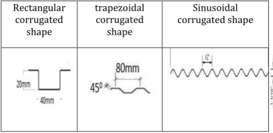
---***---Abstract - Beam, column and slab with corrugated shapes have been extensively used in structural application such as building and bridges. Commonly used Corrugated shapes are trapezoidal, sinusoidal and rectangular. Corrugated shapes show large resistance to shear buckling and has large load carrying capacity and control the bending moment of the member. The aim of this study is to determine the maximum load carrying capacity of connection with corrugated beam, column and slab. Corrugated shape decreases the buckling of the column and bending of slab. The beam, column and slab load carrying capacities are different in different corrugated shapes. Connection of sinusoidal corrugated beam, trapezoidal corrugated column and rectangular corrugated slab can be better for construction purpose than any other combination of beam, column and slab. It is found better in providing different corrugated shapes for the connections of beam, column and slab than same corrugated shapes. Which provides good load carrying capacity.
Key Words: Load carrying capacity, Rectangular corrugated beam, trapezoidal corrugated beam, sinusoidal corrugated beam, ANSYS, Rectangular corrugated column, Trapezoidal corrugated column, Sinusoidal corrugated column…
1. INTRODUCTION
1.1 General Background
Buildings are composed of various structural elements such as slabs, beams and columns. Corrugated web profile can be more economical than conventional plate and improve in the structure. Beam, column and slab with corrugated shapes have been extensively used in structural application such as building and bridges.Commonly used Corrugated shapes are trapezoidal, sinusoidal and rectangular .Corrugated shapes shows large resistance to shear buckling and has large load carrying capacity.
The aim of this study is to determine the maximum load carrying capacity of connection with corrugated beam, column and slab. Now a day’s building and civil infrastructures are becoming larger and higher, the demand for horizontal structure members, which are suitable for long spans so structural steel require high strength but steel member also have many weaknesses, such as less resistance to bucking, excessive deflection, fatigue strength, vibration.
To overcome these disadvantages various types corrugated shapes are developed. corrugations can be applied to strengthen the beams, columns, and slabs of buildings and bridges. It is possible to increase the strength of structural members. The main scope of this study is: to control the bending moment of member, to avoided shear buckling, to implement economic and safety construction, to improve the load-bearing efficiency. The main objectives of this study are follows:Comparative study of load carrying capacity of three different types of cross sections of corrugated beam and column,Comparative study of buckling behavior of three different types of corrugated columns,To create corrugated beam column joint by finding the best load carrying capacity of corrugated beam and column,Comparative study of load carrying capacity different types of beam column joint and finding the best among that,Comparative study of the best load carrying capacity of corrugated beam column joint with three different types of cross section of corrugated slabs,To determine the maximum load carrying capacity of connection with corrugated beam ,column and slab joint.
Rectangular corrugated
shape
trapezoidal corrugated
shape
Sinusoidal corrugated shape
Fig -1: Common corrugated shapes
2. NUMERICAL INVESTIGATION USING ANSYS WORKBENCH 16.1
2.1 Base Model
[image:1.595.302.569.468.598.2]© 2019, IRJET | Impact Factor value: 7.211 | ISO 9001:2008 Certified Journal
| Page 5419
Boundary conditions are(a) beam ,column case one end fixed [image:2.595.327.560.55.209.2]and other end is displaced in downward direction .(b)Beam-column joint with two end is fixed and other end is displaced in downward direction.
Table -1: Geometry of Sections
Descriptions Dimensions
Depth of web 3254mm
Web thickness 363mm
Flange width 3254mm
Flange thickness 363mm
Length of slab 3254mm
[image:2.595.42.284.169.328.2]Width of slab 3254mm
Table -2: Material Properties of Steel.
Young’s modulus of Steel (GPa) 200
Poisson’s ratio of Steel (ν) 0.3
Yield stress ( MPa ) 375
(a)
[image:2.595.374.495.250.368.2]
(b) (c)
Fig -2: Finite element modell of (a)rectangular (b)trapezoidal (c) sinusoidal corrugated beam
(a) (b) (c)
Fig -3: Finite element modell of (a)rectangular (b)trapezoidal (c) sinusoidal corrugated column
Fig -4: Finite element model of connection of sinusoidal beam and trapezoidal column joint
In the finite element analysis fine mesh was adopted for accuracy. The whole model was meshed using 20 node solid 186.
(a) (b)
( c)
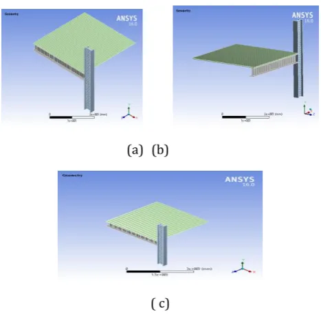
Fig -5: (a)Finite element model of connection of sinusoidal beam, trapezoidal column and rectangular slab(b) Finite
element model of connection of sinusoidal beam, trapezoidal column and sinusoidal slab(c) Finite element
[image:2.595.44.277.355.665.2] [image:2.595.317.551.456.685.2]© 2019, IRJET | Impact Factor value: 7.211 | ISO 9001:2008 Certified Journal
| Page 5420
3. RESULTS AND DISCUSSIONS
[image:3.595.352.513.94.271.2]Maximum value for load carrying capacity and less stress is obtained for sinusoidal corrugated beam compared to trapezoidal corrugated beam and rectangular corrugated beam.Maximum value for load carrying capacity and buckling load carrying capacity is obtained for trapezoidal corrugated column compared to sinusoidal corrugated column and rectangular corrugated column. Connection of sinusoidal corrugated beam, trapezoidal corrugated column and rectangular corrugated slab has maximum load carrying capacity compared with other two types.
Table -3: Maximum load values
mod
els Sinusoidal corrugated Trapezoidal corrugated Rectangular corrugated
beam colum
n Beam Column Beam Column
Load (N) 42×104
[image:3.595.32.292.264.371.2]361×1 04 34×1 04 366×1 04 25×1 04 356×1 04
Table -4: Maximum load values
mode
ls corrugated Sinusoidal beam,trapezoi dal corrugated column and rectangular corrugated slab Sinusoidal corrugated beam,trapezoi dal corrugated column and sinusoidal corrugated slab Sinusoidal corrugated beam,trapezoi dal corrugated column and trapezoidal corrugated slab Load
(N) 474×10
5 388×105 484×105
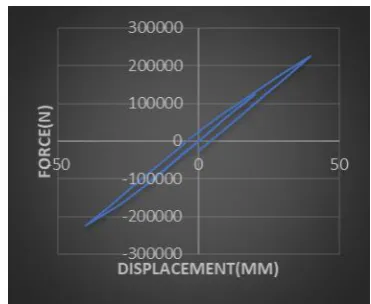
Figure 6 to Figure 9 shows the force -displacement graph. Figure 10 to Figure 13 shows the deformation of models from ansys. -400000 -300000 -200000 -100000 0 100000 200000 300000 400000
-50FOR 0 50
C
E(N
)
[image:3.595.351.516.333.503.2]DISPLACEMENT(MM)
Fig -6: Force-displacement curve of connection with sinusoidal corrugated beam and trapezoidal
corrugatedcolumn joint -300000 -200000 -100000 0 100000 200000 300000
-50 0 50
[image:3.595.339.525.549.701.2]FO R CE (N ) DISPLACEMENT(mm)
Fig -7: Force-displacement curve of connection with sinusoidal corrugated beam column joint
© 2019, IRJET | Impact Factor value: 7.211 | ISO 9001:2008 Certified Journal
| Page 5421
[image:4.595.82.251.73.244.2]Fig -9: Force-displacement curve of connection with trapezoidal corrugated beam column joint
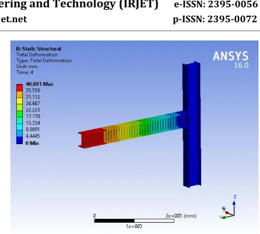
Fig -10: Total deformation of connection with sinusoidal corrugated beam and trapezoidal corrugatedcolumn joint
Fig -11: Total deformation of connection with sinusoidal corrugated beam column joint
[image:4.595.37.287.288.484.2]Fig -12: Total deformation of connection with rectangular corrugated beam column joint
Fig -13: Total deformation of connection with trapezoidal corrugated beam column joint
Rectangular corrugated beam column joint and connection of sinusoidal corrugated beam and trapezoidal corrugated column joint has approximately same stress characteristics compared to other two types. Connection of Sinusoidal corrugated beam and trapezoidal corrugated column joint has maximum load carrying capacity compared with other three types and it is more suitable for construction purpose.
4. CONCLUSIONS
Maximum value for load carrying capacity and less stress is obtained for sinusoidal corrugated beam compared to trapezoidal corrugated beam and rectangular corrugated beam.
[image:4.595.309.559.333.521.2] [image:4.595.38.287.529.717.2]© 2019, IRJET | Impact Factor value: 7.211 | ISO 9001:2008 Certified Journal
| Page 5422
sinusoidal corrugated column and rectangularcorrugated column.
Connection of Sinusoidal corrugated beam and trapezoidal corrugated column joint has maximum load carrying capacity compared with fully corrugated sinusoidal beam column joint, trapezoidal beam column joint and rectangular beam column joint.
Connection of sinusoidal corrugated beam, trapezoidal corrugated column and rectangular corrugated slab has maximum load carrying capacity compared with other two types.
The beam, column and slab load carrying capacities are different in different corrugated shapes.
Connection of sinusoidal corrugated beam and trapezoidal corrugated column and rectangular corrugated slab can be better for construction purpose than any other combination of beam, column and slab.
It is found better in providing different corrugated shapes for the connections of beam, column and slab than same corrugated shapes. Which provides good load carrying capacity.
ACKNOWLEDGEMENT
I wish to thank the Management, Principal and Head of Civil Engineering Department of Ilahia College of Engineering and Technology, affiliated by Kerala Technological University for their support. This paper is based on the work carried out by me (Hafsamol S), as part of my PG course, under the guidance of Mr. Ranjan Abraham (Assistant Professor, Ilahia College of Engineering and Technology, Muvattupuzha, Kerala). I express my gratitude towards her for her valuable guidance.
REFERENCES
[1] Beshara B, Schuster RM. “Web crippling data and
calibrations of cold formed steel members”. AISI Research Report. Canadian Cold Formed Steel Research Group, University of Waterloo, Canada; 2006.
[2] Natário P. “Localized failure of thin-walled steel
members subjected to concentrated loads: analysis, behaviour and design PhD Thesis”. Portugal: Instituto Superior Técnico, Universidade de Lisboa; 2015.
[3] Silvestre N, Camotim D. “Direct strength prediction of
web crippling failure of beams under ETF loading”. Thin-Walled Struct 2016;98:360–74.
[4] Natário P, Silvestre N, Camotim D. “Web crippling of
beams under ITF loading: a novel DSM-based design approach”. J Constr Steel Res 2017;128:812–24.
[5] Prabakaran K. “Web Crippling of Cold-formed Steel
Sections”. Project Report. Department of Civil
Engineering, University of Waterloo, Ontario, Canada; 1993.
[6] Uzzaman A, Lim JBP, Nash D, Rhodes J, Young B.” Web
crippling behaviour of cold-formed steel channel sections with offset web holes subjected to interior two-flange loading”. Thin-Walled Struct 2013(50):76–86.
[7] [7] Uzzaman A, Lim JBP, Nash D, Rhodes J, Young B.”