814
©IJRASET: All Rights are Reserved
Self-Balancing Robot
Mr. Aneesh Kulkarni1, Mr. Sujeet Hange 2 1, 2
Department of Electronics & Telecommunications Engineering, Smt.Kashibai Navale College of Engineering, Pune, India
Abstract: This paper reports the design, construction and control of a two-wheel self-balancing robot. The system architecture comprises a pair of DC motor and an Arduino microcontroller board; 3-axis MEMS (Micro Electrical Mechanical Systems) accelerometer and 3-axis MEMS gyroscope are employed for attitude determination. In addition, a complementary filter is implemented to compensate for gyro drifts i.e. PID. Experimental results show that self-balancing can be achieved with PI-PD control in the vicinity of the upright position.
I. INTRODUCTION
In the past decade, mobile robots have stepped out of the military and industrial settings, and entered civilian and personal spaces such as hospitals, schools and ordinary homes. While many of these robots for civil applications are mechanically stable, such as Aibo the Sony robotic dog, or four-wheel vacuum cleaners, one that ordinary on-lookers would find awe-inspiring is the Segway personal transport, a mechanically unstable, two-wheel self-balancing vehicle that has seen deployment for law-enforcement, tourism, etc. This vehicle can be rightfully called a robot because, without the sensory capability and intelligent control that accompany every robot, the Segway can never stay upright. While Segway may have been a well-known commercial product, research into the control of such a mechanical system has been diverse. A two-wheel self-balancing robot is very similar to the inverted pendulum, which is an important testbed in control education and research; see, for example [1], [2]. Besides the development of Segway, studies of two-wheel self-balancing robots have been widely reported. For example, JOE [3] and nBot [4] are both early versions complete with inertia sensors, motor encoders and on-vehicle microcontrollers. See also an updated reference at the nBot website [4]. Since then, there has been active research on the control design for such platforms, including classical and linear multivariable control methods [3], [5], [6], [7],nonlinear back stepping controls [8], [9], and combinations of the above [10]. A related and interesting work that is worth mentioning concerns balancing of a four wheeled vehicle on its two side-wheels, using classical control [12]. One of the key enabler for this research in the academia is arguably the increasing affordability of commercial off-the shelf (COTS) sensors and microprocessor boards. While JOEfeatured a digital signal processor board, controller boards based on microprocessor such as the 68HC11, ARM and the ATmega series of the Atmel architecture have become the staple in recent years. Arduino is an open prototyping platform based on ATmega processors and a C language-like software development environment, and can be connected with a variety of COTS sensors [13]. It is fast becoming popular platform for both education [14] and product development, with applications ranging from robotics [15],[16] to process control [17], [18] and networked control [19].In this paper, we report a student project on the design, construction and control of a two-wheel self-balancing robot. The robot is driven by two DC motors, and is equipped with an Arduino Uno board which is based on the ATmega328 processor, 3-axis MEMS (Micro Electrical Mechanical Systems) accelerometer and 3-axis MEMS gyroscope. Two control designs based on the linearized equations of motion is adopted for this project: a proportional-integral-differential (PID) control. The approach is found to be robust to modelling errors which can be incurred during experimental determination of such electrical and kinematic parameters as moments of inertia and motor gains. Simulation and experimental results are presented, which show that stability of the upright position is achieved with PI-PD control within small tilt angles.
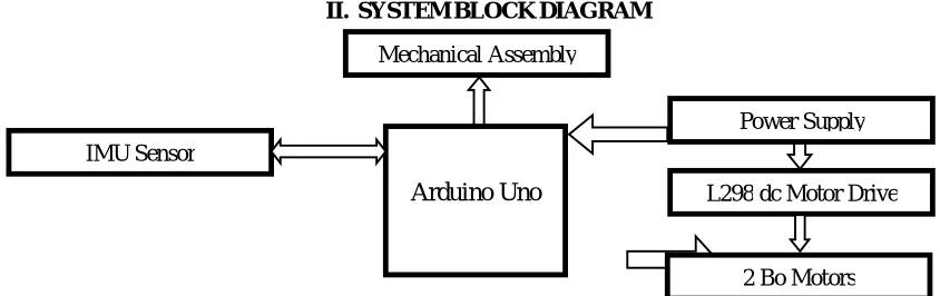
[image:1.612.87.509.585.718.2]II. SYSTEMBLOCKDIAGRAM
Fig. 1 System Block Diagram
Power Supply
L298 dc Motor Drive
2 Bo Motors Mechanical Assembly
IMU Sensor
815
©IJRASET: All Rights are Reserved
A. Block Diagram Description
It consist of various section which are Arduino Uno[13], IMU sensor, L298 dc motor driver, optical isolation, Bo motor.
1) Arduino Uno: The Arduino Uno is a microcontroller board based on the ATmega328 (datasheet). It has 14 digital input/output pins (of which 6 can be used as PWM outputs), 6 analog inputs, a 16 MHz ceramic resonator, a USB connection, a power jack, an ICSP header, and a reset button. It contains everything needed to support the microcontroller; simply connect it to a computer with a USB cable or power it with a AC-to-DC adapter or battery to get started. The Uno differs from all preceding boards in that it does not use the FTDI USB-to-serial driver chip. Instead, it features the Atmega16U2 (Atmega8U2 up to version R2) programmed as a USB-to-serial converter [13].
2) IMU Sensor: It is Inertial Measurement Unit. The sensor gives 3-axis accelerometer and3-axis gyroscope data. The accelerometer measure the force of gravity and it is useful to obtain the robot angle. Gyroscope measures the angular velocity. The combinations of these sensors work well for short period.
3) PID: The control algorithm that was used to maintain it balance on the autonomous self-balancing two-wheel robot was the PID controller. The proportional, integral, and derivative (PID) controller is well known as a three-term controller. The input to the controller is the error from the system. The Kp, Ki, and Kd are referred as the proportional, integral, and derivative constants (the three terms get multiplied by these constants respectively.
4) 2Bo Motors: These are two electrical brushless DC motors. Its RPM is controlled by PWM method. Motors adjust their speed to set the robot at initial set point by adjusting tilt angle by applying the force in the opposite direction of tilt. Two L298 motor drivers are used.
5) L298 Motor Driver: The L298 Driver is a high voltage, high current dual full bridge driver designed to accept standard TTL logic levels and drive inductive loads such relays, solenoids, DC and stepping motors. Two enable inputs are provided to enable or disable the device independently of the input signals. The emitters of the lower transistors of each bridge are connected together the corresponding external terminal can be used for the connection of an external sensing resistor
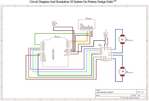
[image:2.612.63.560.374.710.2]Circuit Diagram And Simulation Of System On Proteus Design Suite [20]
816
©IJRASET: All Rights are Reserved
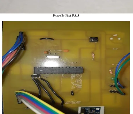
[image:3.612.72.553.81.357.2]III.BOTPHOTOS
Figure 3:- Final Robot
[image:3.612.84.542.312.706.2]817
[image:4.612.125.499.75.321.2]©IJRASET: All Rights are Reserved
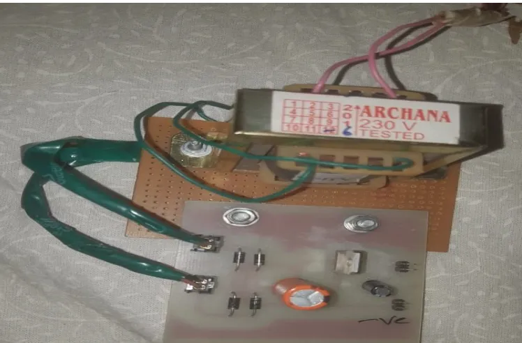
Figure 5:- Power Supply
IV.RESULT
A. Setting Of PID Values 1) Tunning Of KP
a) If value of KP is very low then the bot will not be able to balance properly and will fall often. b) If value of KP is very high then there would be jitter present in motion of bot.
c) At correct value of KP the bot balances perfectly with very less human help. 2) Tunning of KD
a) If value of KD is very high then there would be jitter present in motion of bot. 3) Tunning of KI
a) Now set the value of KI till we get perfect working bot with less jitters and less human help.
B. Our PID values for the bot were 1) KP :- 60
2) KD:- 1.4 3) KI:- 70
C. Our Banking Angle set point was :- 195
V. TOOLSANDTECHNOLOGIESUSED
A. Arduino IDE
B. Proteus Design Suite[20]
C. PcbWizard[21]
VI.CONCLUSION
818
©IJRASET: All Rights are Reserved
VII. ACKNOWLEDGMENT
The project would not have been possible without the kind support and help of many individuals and organizations. We would like to extend my sincere thanks to all of them.
We are highly indebted to our internal guide, Assistant Professor Swapnil D Pujari for his valuable guidance as well as for providing necessary information regarding the project. We would like to express our gratitude towards our project coordinators, Assistant Professor Sangmeshwar kendre And Professor Smita Ingawale for their constant supervision of the progress of our project. We would also like to thank HOD, Dr.S.K.Jagtap for her continuous support. Our sincere thanks to Principal, Dr. A.V. Deshpande for his kind co-operation and continuous encouragement.
Our thanks and appreciations also go to our Professors and our colleagues who have willingly helped us out with their abilities when we faced any difficulty.
REFERENCES
[1] R. Fierro, F. Lewis, and A. Lowe, “Hybrid control for a class ofunderactuated mechanical systems,” IEEE Transactions on Systems,Man and Cybernetics, Part A: Systems and Humans, vol. 29, no. 6,pp. 649–4, nov 1999.
[2] K. Xu and X.-D. Duan, “Comparative study of control methods ofsingle-rotational inverted pendulum,” in Proceedings of the First InternationalConference on Machine Learning and Cybernetics, vol. 2,2002, pp. 776-8.
[3] F. Grasser, A. D’Arrrigo, S. Colombi, and A. C. Rufer, “JOE: A mobile,inverted pendulum,” IEEE Transactions on Industrial Electronics,vol. 49, no. 1, pp. 107–14, 2002.
[4] D. P. Anderson. (2003, Aug.) nBot balancing robot. Online. [Online].Available: http://www.geology.smu.edu/ dpa-www/robo/nbot
[5] R. C. Ooi, “Balancing a two-wheeled autonomous robot,” Final YearThesis, The University of Western Australia, School of MechanicalEngineering, 2003. [6] N. M. A. Ghani, F. Naim, and P. Y. Tan, “Two wheels balancingrobot with line following capability,” World Academy of Science,Engineering and Technology,
vol. 55, pp. 634–8, 2011.
[7] X. Ruan, J. Liu, H. Di, and X. Li, “Design and LQ control of atwo-wheeled self-balancing robot,” in Control Conference, 2008. CCC2008. 27th Chinese, july 2008, pp. 275 –279.
[8] T. Nomura, Y. Kitsuka, H. Suemistu, and T. Matsuo, “Adaptivebackstepping control for a two-wheeled autonomous robot,” in ICROSSICEInternational Joint Conference, Aug. 2009, pp. 4687–92.
[9] G. M. T. Nguyen, H. N. Duong, and H. P. Ngyuen, “A PID backsteppingcontroller for two-wheeled self-balancing robot,” in Proceedingsfo the 2010 IFOST, 2010.
[10] K.-H. Su and Y.-Y. Chen, “Balance control for two-wheeled robot vianeural-fuzzy technique,” in SICE Annual Conference 2010, Proceedingsof, aug. 2010, pp. 2838 –2842.
[11] X. Ruan and J. Cai, “Fuzzy backstepping controller for two-wheeledself-balancing robot,” in International Asia Conference on Informaticsin Control, Automation and Robotics, 2009, pp. 166–9.
[12] D. Arndt, J. E. Bobrow, S. Peters, K. Iagnemma, and S. Bubowsky,“Two-wheel self-balancing of a four-wheeled vehicle,” IEEE ControlSystems Magazine, vol. 31, no. 2, pp. 29–37, April 2011.
[13] Arduino. [Online]. Available: http://arduino.cc/
[14] J. Sarik and I. Kymissis, “Lab kits using the Arduino prototypingplatform,” in IEEE Frontiers in Education Conference, 2010, pp. T3C–1–5.
[15] G. Guo and W. Yue, “Autonomous platoon control allowing rangelimitedsensors,” IEEE Trans. on Vehicular Technology, vol. 61, no. 7,pp. 2901–2912, 2012. [16] P. A. Vignesh and G. Vignesh, “Relocating vehicles to avoid trafficcollision through wireless sensor networks,” in 4th InternationalConference on
Computational Intelligence, Communication Systemsand Networks. IEEE, 2012.
[17] M. J. A. Arizaga, J. de la Calleja, R. Hernandez, and A. Benitez,“Automatic control for laboratory sterilization process rsd on Arduinohardware,” in 22nd International Conference on Electrical Communicationsand Computers, 130-3, Ed., 2012.
[18] S. Krivic, M. Hujdur, A. Mrzic, and S. Konjicija, “Design andimplementation of fuzzy controller on embedded computer for waterlevel control,” in MIPRO, Opatija, Croatia, May 21–25 2012, pp.1747–51.
[19] V. Georgitzikis and I. Akribopoulos, O.and Chatzigiannakis, “Controllingphysical objects via the internet using the Arduino platform over802.15.4 networks,” IEEE Latin America Transactions, vol. 10, no. 3,pp. 1686–9, 2012.
[20] PROTEUS DESIGN SUITE. [Online]. Available: https://www.labcenter.com