Master Thesis
Sousveillance on Intelligent
Transportation Systems
Author:
Djurre Broekhuis
Supervisors: Prof. Dr. Frank Kargl
Dr. Jonathan Petit
Michael Feiri, Dipl.-Inf.
Neal Stephenson, Cryptonomicon
“ In general you could not assume that you were much safer in the country than in Lon-don. There were no telescreens, of course, but there was always the danger of concealed microphones by which your voice might be picked up and recognized; besides, it was not
easy to make a journey by yourself without attracting attention.”
Abstract
Faculty of EEMCS
Services, Cybersecurity and Safety Research Group
Master of Science
Sousveillance on Intelligent Transportation Systems
by Djurre Broekhuis
Intelligent transportation systems (ITSs) are an upcoming technology that allow
vehi-cles and road-side infrastructure to communicate to increase traffic efficiency and safety. One part of such systems is cooperative awareness, where vehicles continually broadcast
messages containing their location. These messages can be received by anyone, and can jeopardize location privacy. In this thesis we research how feasible it is to track a vehicle
in an ITS in the presence of a mid-sized attacker, an attacker that has partial network coverage but can choose which parts to cover. We conduct an empirical study on the campus of the University of Twente by deploying ITS hardware on a small scale. We
determine that road intersections are likely targets for an attacker to eavesdrop, and pro-pose a graph based approach to determine which intersections an attacker should cover.
We then analyse tracking feasibility using a route-based and a zone-based approach, considering both our empirical results and a theoretical expanded scale. Based on these
results, we perform a cost analysis to give an indication of the financial resources an attacker needs to track a vehicle. We then look at pseudonyms as a mitigation strategy, and evaluate different pseudonym change strategies with different privacy metrics. We
find that tracking a vehicle in the presence of a mid-sized attacker is feasible if such an attacker has sufficient resources to cover multiple intersections. We conclude that
This thesis presents the work I have done at the Services, Cybersecurity and Safety
research group at the University of Twente during a six month period. In this time, I worked with various people who contributed their time and effort to my research. First
and foremost, this thesis could not have been completed in its current form without the ideas and advice of my supervisors at the University of Twente, Frank Kargl, Jonathan Petit and Michael Feiri. Beyond being supervisors, I would also like to thank them for
involving me in the PRESERVE project, which allowed me to work with ITS hardware first-hand and enabled me to deploy this hardware for my experiments. Furthermore, I
would like to express my gratitude to Geert-Jan Laanstra for his happily shared expertise and assistance, and the University of Twente security department for allowing me to fill
their patrol vehicle with various equipment. My respect and gratitude also goes out to all the Kerckhoffs students and teaching staff that I have met, worked and learned with in the past two years. Their enthusiasm for all matters security related was a constant
source of inspiration. Finally, I would like to thank my family, my girlfriend, and my friends for their continued support, not only during my thesis, but during the entirety
of my education.
Abstract iii
Acknowledgements iv
Contents v
List of Figures vii
List of Tables ix
Abbreviations x
1 Introduction 1
2 System Model 4
2.1 System Architecture . . . 4
2.2 Attacker Model . . . 7
3 Objectives & Research Questions 10 4 Related Work 12 4.1 Related Work . . . 12
4.1.1 General Tracking . . . 12
4.1.2 General Privacy Issues & Mitigation . . . 14
4.1.3 Mitigation in VANETs . . . 18
4.1.4 RSU Placement . . . 25
5 Experimental Setup 30 5.1 Hardware . . . 31
5.1.1 Sniffing Station . . . 31
5.1.2 Sending Station . . . 31
5.1.3 Power buffer . . . 32
5.2 Simplified Cooperative Awareness Messages . . . 33
5.3 Preliminary Testing . . . 36
5.3.1 Antenna Gain . . . 36
5.3.2 Elevation . . . 37
5.4 Sniffing Station Placement . . . 41
5.4.1 Graphing the Road Network . . . 42
5.4.2 Determining Placement . . . 43
6 Experimental Results 47 6.1 Collected Data . . . 47
6.1.1 Data Clean-up . . . 49
6.1.2 Data Processing . . . 51
6.2 Tracking the Vehicle . . . 55
6.2.1 Most Likely Route . . . 58
6.2.2 Most Likely Zone . . . 61
6.3 Expanding the Scale . . . 63
6.3.1 Expanded MLZ . . . 64
6.3.2 Expanded MLR . . . 66
6.3.3 Real-time Tracking . . . 70
6.3.4 Predicting Coverage . . . 71
6.3.5 Cost Analysis . . . 73
6.3.6 Further Expansion . . . 74
7 Mitigation 78 7.1 Pseudonyms and Pseudonym Change Strategies . . . 79
7.2 Privacy Metrics . . . 81
7.3 Measuring Pseudonym Effectiveness . . . 84
7.3.1 Maximum Tracking Time . . . 85
7.3.2 Including Entropy . . . 92
7.3.3 Hybrid Privacy Flux Function . . . 93
7.4 Expanding the Scale . . . 102
7.4.1 Identifying Intersections . . . 102
7.4.2 Pseudonym Effectiveness . . . 105
7.5 Cost Analysis . . . 110
7.6 Pseudonym Considerations . . . 111
8 Discussion & Conclusion 113 8.1 Discussion & Conclusion . . . 113
8.1.1 Research Questions & Overview . . . 113
8.1.2 Discussion . . . 116
8.2 Future Work . . . 117
8.2.1 Experimentation . . . 118
8.2.2 Tools . . . 118
8.2.3 Tracking Improvements . . . 119
8.2.4 Road Topology . . . 119
8.2.5 Hybrid Privacy Flux Function . . . 120
8.2.6 Silent Periods . . . 120
8.2.7 Privacy Metrics and Mid-Sized Attackers . . . 121
8.3 Final Words . . . 121
1.1 Difference between surveillance and sousveillance [1] . . . 2
2.1 Typical ITS setup . . . 4
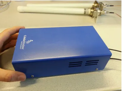
5.1 The Cohda Box used as a sniffing station . . . 32
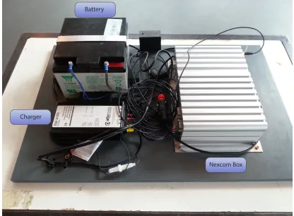
5.2 The battery, battery charger and Nexcom in-vehicle computer . . . 33
5.3 The format of a SCAM . . . 34
5.4 Elevation radiation patterns of a low-gain (left) and high-gain (right) antenna . . . 36
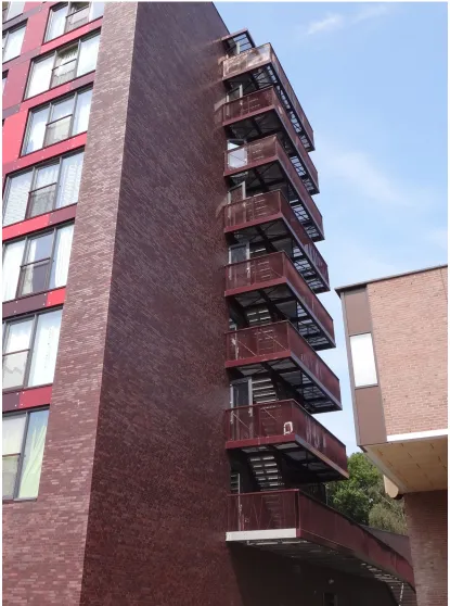
5.5 The building used to perform the elevation experiment . . . 38
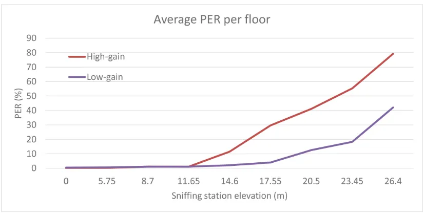
5.6 Average PER per floor for high-gain and low-gain antennas . . . 39
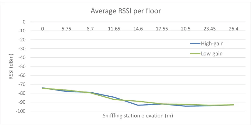
5.7 Average RSSI per floor for high-gain and low-gain antennas . . . 40
5.8 Turning intersections into a graph . . . 42
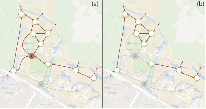
5.9 Intersection graph after covering (a) vertex A and (b) vertices A and B . 44 5.10 Sniffing station placement at intersection A . . . 45
5.11 Sniffing station placement at intersection B . . . 46
6.1 Trip departure times . . . 48
6.2 Trip durations . . . 49
6.3 Dead reckoning tracking time . . . 52
6.4 Predicted paths of different prediction methods . . . 54
6.5 Comparison of prediction performance . . . 55
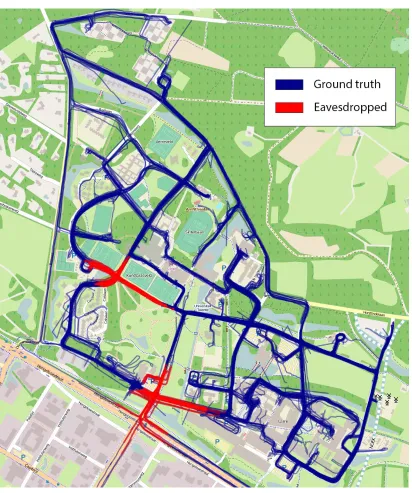
6.6 Overview of all actual and eavesdropped vehicle locations . . . 56
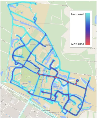
6.7 Heatmap of vehicle locations . . . 57
6.8 The routes used to determine the MLR . . . 59
6.9 Splitting the campus into two zones . . . 62
6.10 Identifying additional intersections between zones . . . 65
6.11 All identified intersections for the expanded MLR approach . . . 67
6.12 Expanded MLR tracking percentage for all intersection combinations . . . 68
6.13 Expanded MLR optimal coverage for 8 intersections . . . 69
6.14 Propagation model showing signals blocked by buildings . . . 72
6.15 A grid plan road network . . . 76
7.1 Maximum tracking time for unlinked trips . . . 87
7.2 Maximum tracking time for combined trips . . . 89
7.3 Privacy level change over a period of 15 minutes . . . 98
7.4 Privacy level for different pseudonym change strategies . . . 98
7.5 Privacy heatmap for an attacker covering two intersections . . . 100
7.6 Privacy heatmap for an attacker covering eight intersections . . . 101
7.7 Map of the Orlando tracking domain and its intersections . . . 104
7.8 Heatmap of vehicle locations in Orlando . . . 105
7.9 Maximum tracking time for (unlinked) trips in Orlando scenario . . . 106
7.10 Maximum tracking time for combined trips in Orlando scenario . . . 107
5.1 Description of SCAM fields . . . 35
5.2 Types of antennas to use for different situations . . . 40
6.1 Most likely route predictions and results . . . 60
6.2 Translation of intersection events to zones . . . 61
6.3 Prediction accuracy for MLZ predictions . . . 63
6.4 Expanded MLZ prediction accuracy for all intersection combinations . . . 66
7.1 Entropy gained per direction for intersection 15 . . . 97
7.2 Entropy gained per direction for intersection 12 . . . 97
BSM Basic Safety Message
CAM CooperativeAwareness Message
DENM DecentralizedEnvironmentalNotificationMessage
DSRC DedicatedShortRange Communications
EMLR Expanded Most Likely Route
EMLZ Expanded Most Likely Zone
GA GlobalAttacker
ICA Intersection Collision Avoidance
ITS Intelligent Transportation System
LA LocalAttacker
LBS LocationBasedServices
LIDR Linear Interpolation-DeadReckoning
MA Mid-SizedAttacker
MTT Maximum Tracking Time
MHB Multi-Hop Broadcast
MLR Most Likely Route
MLZ Most Likely Zone
OBU On-Board Unit
OSM OpenStreetMap
PER PacketError Rate
RSSI Received SignalStrengthIndicator
RSU Road-SideUnit
SCAM SimplifiedCooperativeAwareness Message
SHB Single-HopBroadcast
TTFF Time To FirstFix
VANET Vehicular Ad-hocNETwork
QoS Quality of Service
Introduction
Modern vehicles are becoming increasingly equipped with a multitude of sensors that allow them to gather data on their surroundings. Vehicles may, for example, collect
information about the temperature, road conditions or the distance to other objects and vehicles. Along with these sensors, vehicles are also starting to become equipped with wireless communication systems that allow them to communicate with other vehicles
and infrastructure and set up Vehicular Ad-Hoc Networks (VANETs). Combining these two features allows for cooperative awareness and the development of advanced
applica-tions. These networked, context-aware vehicular networks along with their supporting infrastructure are often called Intelligent Transportation Systems (ITSs).
ITS applications can significantly improve driver safety and comfort, for example by
providing warnings on road dangers or traffic jams, or automatically braking a vehicle when a collision seems likely. At the same time, vehicles collecting and sharing data about themselves and their surroundings gives rise to privacy issues. Many envisioned
ITS applications rely on vehicles knowing the position of both themselves and their neighbours. Therefore, one sort of data that are periodically broadcast as part of
coop-erative safety applications are real-time location and trajectory beacons, a feature that most likely cannot be turned off. Broadcasting these data may jeopardise the location privacy of drivers by allowing them to be tracked.
On the one hand, tracking may be of particular interest to criminals when we consider
certain classes of vehicles, such as police vehicles or money transports. For example, if burglars could track patrolling police vehicles they can wait until all police vehicles are
outside of a certain area before attempting a robbery, which would increase the response
time before the police can be at the crime scene to intervene.
On the other hand, the deployment of ITSs also puts radio networking equipment into the hands of the car owners. In an age where surveillance on the general public seems
to have become common place, ITSs may allow for a role reversal where the general public can record the activities of those usually doing the surveillance. This type of recording by the general public is called sousveillance, and the general setup can be seen
in the cartoon in Figure 1.1. In an ITS where all cars are equipped with networking equipment, anyone is able to eavesdrop on messages from equipment in government or
police vehicles, and use this to try to track them.
Figure 1.1: Difference between surveillance and sousveillance [1]
In this thesis we investigate empirically how feasible it is to track vehicles in an intelligent
transportation system, by deploying ITS equipment on the campus of the University of Twente. Using data from this real-world experiment, we analyse different tracking meth-ods that an attacker can employ. We subsequently investigate a theoretical expanded
scale of the experiment, and describe tracking feasibility in terms of attackers of various levels of resources. By determining the requirements and resources of an attacker we
give a cost analysis, giving us a realistic overview of how likely these attacks on privacy might be in reality. Finally we look at what can be done to mitigate tracking, looking
at pseudonyms as a promising mitigation strategy. We describe the pros and cons of pseudonyms and to what extent they are effective in the context of our experimental data. We conclude that even though pseudonyms cannot eliminate the risk of tracking
more importantly, to raise awareness of the need to ensure such privacy in all upcoming ITSs.
The rest of this document is organised as follows: Chapter 2 gives a description of the system model, describing what components constitute an ITS, the security requirements
of the system, and the classes of adversaries that we consider. Chapter 3 describes the objectives of our research, and states our research questions. Chapter 4 puts our research into context by examining the related work. Chapter 5 describes how the experiment
was set up, and what decisions an attacker needs to make to track vehicles. Chapter 6 describes how the experimental data was processed and analysed, and how this data
can actually be used to track a vehicle. Additionally, this chapter looks at what the effects are if a larger scale is considered, and gives a cost analysis. Chapter 7 looks
at how tracking can be mitigated using pseudonyms, and evaluates the effectiveness of pseudonyms using different privacy metrics. Chapter 8 gives an overview of how we answered our research questions, and what future work remains to be done. Finally, it
System Model
2.1
System Architecture
We consider a VANET consisting of both vehicles and supporting road-side infrastruc-ture. An example of such a set up can be seen in Figure 2.1.
OBU OBU
OBU
infrastructure connectivity
broadcast range (single-hop)
multi-hop forwarding V2V
V2I
RSU
Figure 2.1: Typical ITS setup
To allow vehicles in a VANET to send and receive messages, they are equipped with a
station called an On-Board Unit (OBU). An OBU typically consists of a car computer with networking hardware. An OBU can collect diverse sensor information such as
vehi-cle trajectory data or road conditions, and process and send these data. Apart from the OBUs in the vehicles, there is also static infrastructure to improve data dissemination and to provide connectivity with back end systems. These static infrastructure stations
consist of Road-Side Units (RSUs), which are similar to OBUs except that they are fixed in place and typically have additional network access.
Both OBUs and RSUs can send different types of messages to any other stations that are
in range. The ETSI ITS standard defines two different types of facility layer messages
that vehicles can transmit, namely Cooperative Awareness Messages [2] and Decentral-ized Environmental Notification Messages [3].
Decentralized Environmental Notification Messages (DENMs) enable vehicles to send
asynchronous warning notifications to vehicles, for example when there has been an ac-cident or there are hazardous road conditions. DENMs are delivered to vehicles in the area affected by an event. Messages are forwarded using multi-hop broadcasts (MHB),
where vehicles and RSUs may forward messages so that they reach the appropriate ve-hicles. DENMs are only sent when there has been a noteworthy event, and typically
require reliable packet delivery. Cooperative Awareness Messages (CAMs) support ve-hicular safety and traffic efficiency. Their main purpose is to allow applications to know
about the status of a vehicle or RSU. The ETSI standard specifies that these messages should be broadcast with a frequency of 1-10Hz [2]. CAMs are broadcast only to the immediate neighbourhood of a vehicles, and as such are single-hop broadcasts (SHB). A
typical CAM includes the unencrypted latitude and longitude of a vehicle, its trajectory, a timestamp and an identifier.
In order to send and receive these messages, standardized equipment and protocols must
be used that are suitable for vehicular environments. Due to high node mobility and short intervals of direct connectivity, VANETs have unique network requirements. IEEE 802.11p has been defined as a standard to take into account these requirements
specif-ically for vehicular networks. 802.11p is an amendment to the IEEE 802.11 standard that allows for low overhead and quick connection setup, which is achieved by discarding
all authentication processes [4]. To enable ITS applications, ETSI has allocated 30MHz in the 5.9GHz frequency band. Within this band, 802.11p can use channels of 10MHz
bandwidth to send and receive data.
Security Requirements
The very same features that make ITSs useful may also be abused by attackers. For
example, warning vehicles of hazardous road conditions is one of the envisaged appli-cations of VANETs. However, this functionality may also be abused by an attacker
purposefully reporting incorrect conditions. This could cause a vehicle to brake unnec-essarily, which in turn could lead to accidents. Vehicles could also try to masquerade as other vehicle to try to escape liability in the case of an accident. These simple examples
amongst vehicles and infrastructure must be secured. Papadimitratos et al. and Raya and Hubaux identify the following basic security requirements that VANETs need to
satisfy for secure safety messaging [5] [6]:
• Authentication and Integrity: When a vehicle receives a message, it should corrob-orate that the sender is a legitimate vehicle in the network and that the message
has not been changed. If this is not done, the receiver may react to incorrect messages which could cause a hazardous situation. Thus messages need to be
checked for authenticity and integrity, for example by including signatures and certificates in the messages. Note that as 802.11p does not include any of the MAC layer authentication features that are present in standard 802.11, this needs
to be implemented at higher layers such as the network layer.
• Data Consistency: Message legitimacy can also be analysed by looking at data consistency. For example, if the same legitimate vehicle sends two contradicting
messages, then the receiver can question the legitimacy of these messages.
• Availability: Vehicles rely on network availability to receive safety messages. For example, if the network is not available during a hazardous scenario, then an
accident may occur. Thus the network needs to be resilient against both network congestion and denial of service attacks.
• Non-repudiation: Senders should not be able to deny that they have transmitted any specific message, as which vehicle sends which message may be important
when investigating a traffic accident.
• Privacy: VANETs should protect the personal and private information of its users. This means that this information should not be disclosed directly, but it should
also not be possible to make inferences that reveal private data.
• Real-time Constraints: The high node mobility and short connectivity intervals of VANETs mean that there are real-time network limitations. Thus strict time
constraints need to be adhered to, to ensure that vehicles receive the required messages.
Apart from the above, Schaub et al. and Bibmeyer et al. identify another security
re-quirement, namely accountability [7] [8]:
• Accountability: When vehicle misbehaviour is detected or when there is an acci-dent, it is desirable that authorities are still able to identify which vehicle was the
In our system model we concern ourselves primarily with privacy, and in particular lo-cation privacy. However, privacy may also have a direct effect on other requirements.
For example, privacy may be ensured by making all messages completely anonymous, but this contradicts the requirements of authentication and accountability. We will see
later that non-persistent identifiers called pseudonyms are often suggested to provide location privacy, while still allowing for authentication and accountability.
Attacker
We have seen that CAMs are periodically sent by vehicles, and that they contain un-encrypted location beacons. This means that an attacker with 802.11p equipment can receive these CAMs and possibly track any vehicle. In our system model, we consider
an attacker using such equipment as sniffing stations. These sniffing stations can be deployed to areas to allow eavesdropping on any location beacons within range. A
sniff-ing station is similar to an OBU or RSU, consistsniff-ing of hardware which allows it to receive and process 802.11p packets. The main difference is that a sniffing station is not
physically constrained to one place or vehicle, the attacker is free to place the station where he/she wants. The number of sniffing station that an attacker can have is limited by the available resources of the attacker. We will look more closely at these resources
in chapter 6. An attacker can use these sniffing stations to eavesdrop on the positions beacons of any vehicles that are in range of a station. The next section describes which
characteristics we consider to constitute an attacker.
2.2
Attacker Model
Similar to Raya and Hubaux, we identify 5 different properties that describe an attacker in our system model [6]:
• Scope: The scope is the area over which the attacker can eavesdrop. On one end of the spectrum is theglobal attacker, which has complete coverage and can eavesdrop
on any message that has been transmitted in the network. On the other end of the spectrum is the local attacker. This is an attacker that can only cover one small
• Passive/Active: A passive attacker is only capable of receiving and processing any packets that it receives, whereas an active attack can also inject packets into the
network.
• Internal/External: An internal attacker possesses keys and credentials that make it a legitimate participant of the system, whereas an external attacker does not.
• Honest/Dishonest: An honest attacker complies with the implemented protocols, whilst a dishonest attacker can deviate from them.
• Tracking Period: The tracking period defines over what period an attacker tries to link location samples and track a vehicle. We distinguish between the following:
– Short-term tracking means that an attacker tries to link consecutive location samples occurring in a time frame of a couple of seconds. Given multiple
location samples of different vehicles, the attacker tries to link the location samples to the specific vehicles that sent them.
– Mid-term tracking means that an attacker tries to link position samples from a single trip. A vehicle trip is the entire time period from when a vehicle
start a journey until it ends, and can be in the order of a couple of minutes to a couple of hours.
– Long-term tracking means that not only does an attacker try to link consec-utive location samples, but it is also tries to link different sets of location
samples from different trips. Long-term tracking can cover a time period of over one day. For example, the attacker tries to identify that a police vehicle
that was tracked in a certain area one day is the same vehicle that passes through that area the next day or a couple of days later.
We do not consider all the described attacker properties. Firstly, we do not consider
active attackers. CAMs are broadcast without any interaction from other vehicles, and so actively injecting packets into the network is not necessary. For the same reason we also do not distinguish between honest and dishonest attackers, as for CAMs there are
no communication protocols to comply to. We also do not make a distinction between internal and external attackers because the CAMs that we eavesdrop on are not
en-crypted, and can be read by both internal and external attackers. Finally we are not interested in short-term tracking, as we want to investigate where a vehicle is in a certain
areas, hence covering a single trip to multiple trips.
Taking into account these limitations to the attacker model, this leaves us with three
following a target to track it. A GA on the other hand can observe the entire area and is just as hard to defend against. A more interesting and more realistic scenario is that
of the MA: an attacker that has partial coverage of the entire network, but is capable of choosing which parts of the network area it covers. How much an MA can cover is
Objectives & Research Questions
We consider an MA that has distributed yet limited coverage of a vehicular network, using sniffing stations to eavesdrop on CAMs containing position beacons. However, the
positions of these sniffing stations will affect the coverage, and with it the strength, of an adversary. There are a number of variables that come into play when considering sniffing station placement. One aspect that may have a significant effect is how high
the sniffing station is placed. A sniffing station at ground level most likely has a smaller coverage area than one that is placed higher. This leads us to our first research question:
• How does the vertical positioning of a sniffing station affect its coverage area?
A second matter is where to place the sniffing stations in the network so that an attacker
can maximize network coverage at minimum cost. This problem is not all that dissimilar to the problem of determining where RSUs should be placed when deploying ITSs. The models that are used to determine the placement of RSUs may be adaptable to improve
the coverage of an MA. This gives the following research question:
• How can an attacker determine where sniffing stations should be deployed?
An MA by definition does not have full network coverage. However, full network coverage may not be necessary to still allow for tracking a vehicle in the entire network. An
attacker could use street-level knowledge to place the sniffing stations in areas that give the most information to assist in tracking. Intersections are often proposed as the optimal place to position sniffing stations, so an attacker could use knowledge of where
intersections are to decide where to place the stations. However, real-world tests on these placement strategies are still lacking, leading to the research question:
• Is an MA that uses street level knowledge to only eavesdrop on intersections ca-pable of mid-term and long-term vehicle tracking in a real-world scenario?
Next, we consider the effectiveness of mitigation strategies. Pseudonyms are most com-monly proposed as (part of) mitigation strategies to increase unlinkability and so reduce
the risk of tracking. However, the effectiveness of pseudonyms have mostly been stud-ied in theoretical contexts and in the presence of a global attacker. To our knowledge, there have not been any privacy studies with actual 802.11p hardware and mid-sized
attackers. To measure the effectiveness of pseudonym changes, there have been many proposed location privacy metrics. Real world experimentation would give an
opportu-nity to validate pseudonyms in the context of these privacy metrics. This gives rise to the research question:
• How effective are pseudonyms as a strategy to mitigate tracking and how can this be measured?
Finally we look at the strength of an MA. We define the strength as the amount of
resources an attacker has, and so the extent of the network that it can cover. The strength of an MA can thus lie anywhere between the LA and the GA. The results of
the previous research questions can potentially be used to model a relation between the strength of an MA and its capabilities. This gives our final research question:
Related Work
4.1
Related Work
Tracking mobile nodes has been an active area of research as mobile nodes themselves become more and more ubiquitous. In this section we give an overview of related work
on tracking in VANETs and other domains, as well as mitigation techniques.
4.1.1 General Tracking
Mobile phones are the most prevalent type of mobile nodes and because of this it has
been a popular topic for mobile tracking. Drane et al. examined the ability to derive position information from GSM signals, and analysed which features of GSM signals are relevant for positioning a mobile phone [9]. They identified propagation time, time
difference of arrival, angle of arrival and carrier phase as different positioning techniques that can be used to determine the position of a phone. However, propagation time and
time difference of arrival require accurately synchronised clocks between mobile phones and base stations.
They also defined two different types of positioning, namely mobile-based positioning and network-based positioning. Mobile-based positioning is where a mobile phone uses the signals transmitted by different base stations to determine its position.
Network-based positioning on the other hand, uses signals transmitted by the mobile phone and received by the base stations to perform the positioning. A hybrid approach is also
possible, which takes aspects from both of these methods.
Cell ID
Another way of positioning mobile phones is by Cell ID [10][11]. A Cell ID is a unique number used to identify each base transceiver station in a GSM network, and base
transceiver stations continually broadcast their Cell ID. As a mobile phone continually receives these broadcast messages, it can approximate its position using the known
geo-graphical coordinates of the base transceiver station. However, as the distance that may be covered is large, the accuracy of this method is limited. Experimental results give an average accuracy of 500 metres in urban environments [10].
Signal Strength
Tracking mobile phones is also possible using the signal strength of static base stations.
Chen et al. used the signal strength of GSM signals to estimate the location of a mo-bile device [12]. They analysed three different positioning algorithms in a real-world
scenario. The first method uses the Cell ID of base transceiver stations which have a known location. By weighting the received signals with the received signal strength, an estimation of the location of the mobile phone can be made. A second algorithm that
they analysed uses fingerprinting of received signal strengths. First a training phase takes place, where signal strengths from all base transceiver stations are recorded for all
locations. A mobile phone can then search this index of radio fingerprints and locations, and choose thek fingerprints with the lowest Euclidean distance from the current radio
fingerprint. The location of the device is then estimated as the average of the locations of these best k matches. A final positioning algorithm that they analysed uses a radio propagation model and Markov localisation. This method is similar to radio
fingerprint-ing, but instead of a training phase, the fingerprints are created by using an abstract model of the signal environment. A sensor model is built to predict the signal strength
at each location, and then a Bayesian particle filter is used to determine the likelihood of measurements and so estimate the mobile phone’s true location.
They found that in a high fingerprint density area, the basic fingerprinting algorithm is most effective, with an average error of 94 metres. In lower density areas, the modelled fingerprint method works the best, with an average error of 196 metres.
One downside of the basic fingerprinting approach is that it is a deterministic process,
where it is assumed that the signal strength does not change over time. Ibrahim and Youssef improved on these techniques by taking a probabilistic approach that they called
location during the training phase, a signal strength histogram is built up over time. As this significantly increases the training overhead, a grid-based approach is taken where
a histogram is built up for each grid area instead of for each location. The location of a mobile phone can then be estimated by calculating the average location of the k most
probable locations given the observed signals strengths. With these improvements, they found the average accuracy to be 30 metres and 105 metres for urban and rural areas respectively. Under the same urban conditions, this represents a 23.8% increase over
the basic fingerprinting technique and a 157.1% increase over the modelled approach. In rural areas the improvements are 197.5% and 86.4% respectively.
Due to the limited accuracy, the above positioning methods are not suitable for
vehicu-lar networks. Safety applications in particuvehicu-lar require sufficient accuracy to distinguish cars, and so this accuracy needs to be in the order of a couple of meters. For this reason, GPS is used in ITSs to establish vehicle positions with high accuracy.
Other Domains
Apart from tracking mobile phones, the above techniques have also been applied to other
domains. Oka et al. used received signal strength measurements for tracking targets in wireless sensor networks [14]. As opposed to signal strength tracking in GSM networks,
the target that is to be tracked sends out signals, and the signal strength is measured at the receivers. Time-of-flight measurements for localisation are used by the Cricket [15] and Active Bat [16] systems. Again there is a difference in whether the mobile node
or the infrastructure performs the positioning measurements. In the Cricket system, a passive mobile device measures the time-of-flight from infrastructure transmitters. For
the Active Bat system this is vice versa, with the mobile device sending out signals to a grid of static receivers. Both systems require line of sight between the transmitters and
receivers, and thus require sufficient infrastructure for full coverage. This line of sight requirement means that this method of localisation is not suitable for vehicular networks.
4.1.2 General Privacy Issues & Mitigation
done on identifying and analysing these privacy issues.
Location Privacy
Duckham and Kulik defined location privacy as a special type of information privacy which concerns the claim of individuals to determine for themselves when, how and
to what extent location information is communicated to others [17]. They also identi-fied three negative effects associated with a failure to protect location privacy, namely location-based spam, personal well-being and safety, and intrusive inferences. The
lat-ter is most relevant to the issue of tracking, as being able to identify at which times a person is at which locations allows for inferences of, for example, a person’s political
views, state of health or personal preferences [18].
Furthermore, they identified four different strategies for protecting location privacy.
Firstly, regulatory strategies include rules, laws and fair information practices that allow people to control their location information. Secondly, privacy policies are trust-based mechanisms that rely on implementing parties to adhere to these. However, policies are
not privacy enforcing, and are vulnerable to malicious behaviour. Third is anonymity, which dissociates information about an individual from that individual’s actual location.
A final strategy that they proposed was obfuscation. Here, the quality of information about a person’s location is degraded to protect that person’s location privacy.
Regula-tory strategies and privacy policies fall out of the scope of our research, and as such, we focus on technical solutions such as anonymity, pseudonymity and obfuscation.
Anonymisation
As mentioned above, anonymisation is offered as a potential solution to tracking, and in particular to intrusive inferences as described by Duckham and Kulik [17]. However,
even when all identifiers are removed, anonymised location samples are not sufficient to mitigate tracking as there is a high correlation between successive location samples.
There are well-established techniques to link consecutive location samples to create tra-jectories, and even to link these to individual people [19]. For example, Gruteser and Hoh used multi-target tracking to accurately link completely anonymised GPS location
samples from 3 different people, and went on to successfully demonstrate the same at-tack on GPS data from 5 different people [20] [21]. Thus, naive anonymisation is not
various security requirements. For example, we have seen in Chapter 2 that account-ability is an important requirement for ITSs. If all messages are completely anonymous
however, then accountability is not possible. Pseudonyms aim to solve these problems by allowing an individual to be anonymous whilst keeping a persistent identity.
Perturbation
Gruteser proposed to increase unlinkability between consecutive location samples by a perturbation algorithm that aims to mitigate the problem of trajectory tracking [21].
They investigated a mechanism that prevents an adversary from tracking a complete individual path by introducing tolerable errors into location samples. In their setup,
location samples are first sent to an anonymisation server, which acts as a proxy and forwards the data to Location Based Services (LBSs). These LBSs can then use the
anonymised location samples. Thus they consider the privacy problem after transmit-ting these samples to an untrusted third party application service. However, to ensure that these services are still useful to a user, they aim to increase the level of confusion
while still enabling statistical location-based applications.
The key idea underlying their solution is the concept ofpath confusion. Every time two
nodes come into close proximity, the location samples of both nodes are perturbed so that there is a chance that the adversary confuses the two tracks. This is achieved when
two nodes travel parallel to each other for a short segment; the location samples are perturbed so that it seems as if the paths cross. After this, it is harder for an adversary to distinguish which node is which from the location samples. There are however also a
number of drawbacks to their proposed solution. Firstly, they formulate perturbations as a constrained non-linear optimisation problem, which results in a computationally
complex system that is not feasible for deployment in a real-time information systems with large numbers of users. Secondly, adequate privacy only achievable if user density is sufficiently high. Unfortunately, perturbation is not suitable for location samples in
CAMs, because vehicular safety applications rely on the position information that is broadcast being as accurate as possible.
CliqueCloak
Another solution to prevent tracking is by spatiotemporal cloaking; location samples are
results from location based services, which means that additional local filtering is re-quired, which in turn results in higher computational and network costs. Furthermore,
temporal cloaking may increase network delays which may lead to a lower perceived quality of service (QoS) [22].
A framework for allowing a user to specify a level of cloaking according to the preferred level of privacy was proposed by Gedik [22]. In this framework, a user can specify per message the minimum level of required privacy as measured by the users k-anonymity,
which indicates that the user is not distinguishable from k-1 other users [23]. Along with this, the user can also specify the preferred spatial and temporal tolerances as a set
of anonymisation constraints. Before location samples are sent to an LBS, they first go through a message perturbation engine which performs the anonymisation and cloaking according to these anonymisation constraints. To determine which other messages need
be considered and how much they need to be cloaked, they model the anonymisation constraints as a constraint graph. Two messages are connected in the constraint graph if
they are sent by different mobile nodes and their spatiotemporal points coincide, taking into account the specified spatiotemporal tolerances. They then translated the problem
into the problem of finding cliques that satisfy certain conditions in the constraint graph. As such, they called their system CliqueCloak. Similar to the perturbation method de-scribed above, VANET safety applications rely on accurate spatiotemporal samples and
so CliqueCloak is not suitable in this case.
Mix-zones
A different way to make it harder for an adversary to determine which node is which is by using mix-zones [24]. A mix-zone is analogous to a mix-network as originated in the
work of Chaum [25]. In a mix network, a mix-node collectsnequal length messages, adds padding, reorders them by some metric and forwards them in the new random order, giving unlinkability between incoming and outgoing messages. A mix-zone, on the other
hand, considers a Euclidean space without spatial constraints [26]. A set ofkusers enter in some order and change identifiers (or pseudonyms). No users leave before all users
are in the zone, and they spend random time inside before exiting in different order. Assuming that inside a mix-zone the location cannot be tracked, this gives unlinkability
between the old and new pseudonyms. A mix-zone works in a similar way for mobile nodes. A mix-zone is an area in which a mobile node does not request any location based information, and thus does not need to send its location. Assuming that a user changes
the same time. Thus nodes going into a mix-zone cannot be linked with those coming out of it. Mix-zones can be suitable for VANETs as well, as described in the next section.
4.1.3 Mitigation in VANETs
Mix-zones have also been proposed as solutions for tracking in vehicular networks. How-ever, there are a number of issues that complicate the situation for mobile nodes and for
VANETs in particular. Firstly, vehicles will not spend a random time inside a mix-zone, there is a correlation between ingress and egress times. Secondly, there is also a corre-lation between where vehicles enter and exit the mix-zone due to the spatial constraints
of the roads themselves. This means that the transition probability is not uniform, but constrained by limited trajectory paths and speeds of travel. A node may enter a
mix-zone with a known and predictable trajectory, which leaks information that may make it easier to link egress events with ingress events.
One simple way to model mix-zones in VANETs is to define any area that is not ob-served by an adversary as a mix-zone, as was done by Butty´an et al. [27]. Of course, it is almost impossible to detect which areas are and which are not covered by an observer.
Freudiger et al. proposed to force the establishment of mix-zones at appropriate places in VANETs to achieve location privacy in the presence of randomly changing identifiers
and a global passive observer [28]. The effectiveness of mix-zones depends heavily on the density of vehicles and the unpredictability of their whereabouts. Therefore they
suggested to establish mix-zones at vehicle intersections, which generally have a high density of vehicles that change direction.
CMIX
Vehicular mix-zone were also proposed in the CMIX protocol of Freudiger et al. [28]. In their CMIX protocol, all legitimate vehicles in a mix-zone get a symmetric key from
a RSU. Key forwarding is used to ensure that the vehicles already possess this key the moment they enter the mix-zone, which is essential for safety application. Once in the mix-zone, all messages are encrypted with this key, meaning that a global observer can
no longer see the content of messages and the location information contained within them, resulting in unlinkability between vehicles entering and subsequently exiting
network can place a vehicle at one or more mix-zones and obtain the keys and decrypt the encrypted messages. The system also requires an authentication mechanism to
en-sure that only legitimate users can obtain the key. Furthermore, a GA can observe the ingress and egress of vehicles in mix-zones and get a probability distribution of possible
mappings, which gives some information that may still make tracking possible. With an adversary that knows only the set of vehicles entering or exiting a mix-zone, the level of privacy is only dependent on the number of vehicles in the mix-zone. With a stronger
adversary that also knows trajectory and timing information the level of privacy also depends on the delay characteristics of the intersection and the vehicle trajectories. To
somewhat alleviate this problem, they propose using several mix-zones in a chain to create a mix-network. They show with simple simulations that unlinkability of individ-ual mix-zones is generally low, but this can be greatly improved by chaining mix-zones.
However, the performance of their system is heavily dependent on vehicle density, as less congestion can make vehicles easier to track. The protocol also assumes that all vehicles
participate in the anonymisation process.
MobiMix
MobiMix aims to solve some of the shortcomings of the CMIX protocol, by taking into account the spatial constraints and limitations of the road network, the timing of vehicles
entering and exiting a mix-zone, and the transitioning probability in terms of movement trajectories [26]. This prevents timing attacks, which rely on the correlation between ingress and egress times to decreases the anonymity set size as well astransition attacks,
which estimate probability of each possible turn at an intersection.
To achieve this Palanisamy and Liu proposed to construct the mix-zone using differ-ent techniques [26]. The basic technique is the ’naive rectangular’ method, where the
mix-zone is a regular rectangle around an intersection. With this technique, all users in the mix-zone at the same time are in the same anonymity set. The CMIX protocol described above resembles this technique most closely, as all vehicles within range of an
RSU are considered to be in the same mix-zone. The main downside of this method is that at the moment a vehicle enters the mix-zone, some vehicles in its anonymity set
may already have been in the mix-zone for a much longer time, and thus are more likely to leave earlier.
A second mix-zone construction technique tries to solve this issue and is called ’time
vehicles that enter within a certain time window of that event. The size of this time window is based on the characteristics of the road junction. However, even taking this
into account, information may still be leaked by differences in speed distributions (for example due to different road classes) which could lead to timing attacks.
A third mix-zone construction technique is ’time window bounded shifted rectangular’. This is similar to the method above, but it is not centred around a junction. Instead it is shifted so that it takes the same time from all directions to reach the centre of the
junction assuming all vehicles travel at a certain mean speed. Thus it takes into account the speed characteristics of the road network. The downside of this method is that it
does not perform well when vehicles deviate from the mean speed.
The last mix-zone construction technique that they proposed is the ’time window bounded non-rectangular’ approach. This approach is again similar to the previous one, but now
mix-zones start from the centre of the junction and only cover the outgoing road sec-tions. The length of the mix-zone on each segment is based on the mean speed of the
segment, the chosen time window and the desired level of privacy. They found that this last mix-zone construction is the most effective and immune to the timing attacks that
are possible with the other techniques. However, it does require a mix-zone length of a couple of hundred metres on each outgoing segment.
Pseudonyms
Pseudonyms have also been offered as possible solution in VANETs to increase unlinka-bility between location samples. A pseudonym is an abstract identifier that a vehicle can
use to communicate. Most theoretical models on pseudonyms originate from the work of Chaum [25]. Since then, a lot of work has been done to determine how pseudonyms
can be used to mitigate the privacy problems of mobile node tracking. However, using a single abstract identifier still allows linking of consecutive location samples to each other and through this even to an individual. For example, Gruteser and Alrabady analysed
one week of pseudonymised GPS traces from drivers in Detroit, and their home-finding algorithm was able to find plausible home locations for 85% of the drivers [29]. Krumm
used pseudonymised GPS traces to determine the location of a driver’s home with a median accuracy of 61 metres [30]. Using a reverse white pages lookup, they were able
to correctly identify the correct home address of a driver 13% of the time and their names 5% of the time. To decrease this sort of linkability, pseudonyms can be changed periodically. Note that pseudonyms need to be changed on all communication stack
Simple Pseudonym Change
How and when to change pseudonyms is still an open research challenge, and there have been many different proposed pseudonym change strategies [31]. Wiedersheim et al.
analysed the effectiveness of simple change strategies, where a pseudonym is changed every message or every few seconds [32]. They considered a GA that can receive all
beacon messages that are sent in the network. By using multiple hypothesis tracking and Kalman filtering on a large quantity of pseudonymous position samples, they tried to connect those samples to location profiles or tracks. Using simulations, they found
that even when changing the pseudonym every message and sending a beacon every second, tracking is largely successful. However, it is unlikely that pseudonyms can be
changed this often as vehicles will probably only have a limited number of pseudonyms and thus cannot change pseudonyms every message [33].
Increasing the time that a vehicle uses one pseudonym increases that chance of tracking success even more, and they find that with 20% of vehicles sending a beacon every sec-ond and changing pseudonyms every 10 secsec-onds, a vehicle can be tracked almost 100%
of the time. Thus it seems that simple pseudonym change strategies are not sufficient to ensure location privacy in the presence of a GA.
Swing & Swap
More complex pseudonym change strategies were proposed by Li et al. [34]. They
de-vised two different pseudonym change strategies called Swing and Swap. Swing enables nodes to independently initiate and loosely synchronise pseudonym updates, whereas Swap is an extension of Swing which allows nodes to exchange identifiers. Both
ap-proaches are user-centric in that nodes can independently determine when and where to change pseudonyms to increase their location privacy, whereas with other solutions such
as mix-zones this can only happen at fixed locations.
Swing improves location privacy because asynchronous location updates limit the loca-tion privacy provided by each update [17]. By initiating synchronised updates at oppor-tune locations and times, the size of the anonymity set can be increased and tracking
may be mitigated. The anonymity set of a node includes nodes that update their iden-tifiers along with the initiating node and appear in the reachable area of the target.
Swing works by a node first initiating a pseudonym change. This node then monitors the channel to ensure that the neighbourhood size is at least 1, and if it is it broadcasts a
their pseudonyms as well, giving loosely synchronised updates within the neighbourhood of the initiating node. After changing its pseudonym, each node enters a random silent
period where it no longer broadcasts any messages. In order to prevent an adversary from using the predictability of node movement to correlate node positions, pseudonym
updates are only performed when changing direction and/or speed. Note that not all neighbouring nodes have to change their pseudonym when receiving an update message, as some may already be at their desired level of anonymity. As such, Swing does not
account for neighbours that do not update their identifiers and which may decrease the size of the anonymity set.
Swap builds on Swing, but instead of nodes always updating their pseudonyms, they
swap pseudonyms with probability of 0.5 and then enter the random silent period. With this method, neighbours of the target contribute to its anonymity set despite not updat-ing identifiers, as long as they change their velocity and broadcast only durupdat-ing a specific
interval in the exchange process. Nodes have an incentive to cooperate as they are pro-vided with enhanced privacy enhancement whilst conserving the number of pseudonyms
that they have. Swap may have a larger and more uniformly distributed anonymity set, but it does come with additional protocol overhead caused by the actual swapping of
the pseudonyms and the additional identity management that is required. Using sim-ulations, Li et al. found that Swap outperforms Swing, and that both are better than random pseudonym updates when it comes to location privacy. They also found that
location privacy increases when the silent period is longer. Unfortunately, both Swing and Swap assume that a node can estimate when and where a trajectory change can
occur, and Swap is only possible with extra infrastructure for identity management.
Mix Contexts
Gerlach and Guttler proposed a different method of synchronising pseudonyms changes to increase location privacy [35]. They introduced the concept of mix-contexts, where vehicles use context information such as the number of neighbours, their direction and
speed to decide whether or not to change pseudonyms. Thus nodes cooperatively iden-tify good opportunities to change pseudonyms, based on when the context allows for at
least a certain amount of anonymity (for example, when a certain number of vehicles in range are travelling in a similar direction). After changing its pseudonym, a vehicle assesses whether the change was successful based on how many other nodes changed at
Silent Cascade
Another pseudonym change strategy is Silent Cascade, as proposed by Huang et al. [36]. Silent Cascade tries to use pseudonyms to achieve unlinkability between location
samples without violating a user’s QoS requirements. This method builds on silent pe-riods, which increase privacy at the cost of losing communication time. Silent Cascade
enhances location privacy while reducing this QoS degradation. Silent Cascade works with two states. In the active state, a node uses one specific pseudonym as a commu-nication identifier. In the silent state, a node is not allowed to disclose either its old
or new pseudonym, and thus is equivalent to a silent period. A silent cascade is then defined as a duration of time where a node switches between the silent state and active
state periodically. Thus a node switches its operation mode from active state to silent state after each pseudonym update. After staying in silent state for certain period of
time, the node switches back to active state so that it can communicate normally. Af-terwards, the station iteratively switches its operation mode between active state and silent state. Each time the node enters the silent state, it introduces ambiguity into the
time and place when the pseudonym change occurred. The maximum amount of time that a node can stay in either of these states it determined by the QoS requirements. In
effect, this create a chain of mix-zones as described in [27]. Silent Cascade adds an addi-tional trade-off parameter to basic silent period. Whereas with basic silent periods there
is a trade-off between anonymity and QoS, Silent Cascade adds a third parameter in the form of the silent cascade delay, which allows it to ensure a user required level of QoS.
CARAVAN
The CARAVAN scheme attempts decrease linkability between location samples by in-creasing the length of the silent period [37][38]. Sampigethaya et al. propose to do this
by allowing vehicles to form groups, where vehicles are defined to be in a group if each group member can receive the broadcasts of every other group member. Then, since
vehicles in a group move relative to each other and have on average the same velocity, the group can be seen as a single large vehicle represented by the group leader. The
group leader then communicates on behalf of all vehicles in the group, and the other vehicles can extend their silent period for as long as they are a member of the group. Group members can also use the group leader as a proxy to increase unlinkability.
Un-fortunately they only analyse their scheme with a freeway model and a simple street model. This may not capture the true mobility of vehicles, the dynamic nature of which
Pseudonym Trade-offs
With the many different proposed pseudonym change strategies, it is important to con-sider what trade-offs come with introducing pseudonyms into an ITS. Lefevre et al.
investigated the effects of pseudonym changes strategies on an intersection collision avoidance (ICA) system [39]. To do this, they simulated an intersection and analysed
the effects of three different pseudonym strategies: fixed-id, baseline and adaptive. In the fixed-id case there are no pseudonym changes at all, but a vehicle uses one long term pseudonym. In the baseline case pseudonyms are changed every 120 seconds and
each change is followed by a random period between 0 and 13 seconds. The current SAE J2735 standard for Dedicated Short Range Communications (DSRC) proposes a
silent period of 50 to 250 metres or 3 to 13 seconds, whichever comes first [40]. Finally they proposed the adaptive strategy, which is similar to the baseline strategy except
that a pseudonym change is only authorised if it does not affect the safety application. They analysed the effectiveness of these three strategies using the rate of missed accident interventions, the rate of avoided collisions, and the rate of failed interventions. They
found that silent periods longer than 2 seconds strongly affect ICA applications, and that the adaptive approach only authorised average of 10 percent of pseudonym changes
when the silent period was larger than 2 seconds. This indicates that whilst pseudonym changes and silent periods may be beneficial for location privacy, they may also have an
impact on the main functionalities of an intelligent transportation system.
Pseudonym Effectiveness
To determine how effective changing pseudonyms are, Butty´an et al. defined a model that allows this to be studied [27]. To do this, they defined all areas that are unobserved by an adversary as a mix-zone. As vehicles do not know when they are in mix-zone,
pseudonyms are constantly changed. They assumed that this rate of change is high enough that pseudonyms are changed at least once per mix-zone. Under this
simplify-ing assumption they simulated vehicles in a part of Budapest coversimplify-ing 59 road junctions, attempting to give a relationship between strength of the adversary and level of location
privacy achieved by changing pseudonyms. The adversary strength was varied by eaves-dropping on thekbusiest junctions, with an eavesdropping range of 50 metres. Different traffic densities were simulated and then they quantified the success of the adversary
by calculating the number of successful tracking attempts. Tracking was considered a success when a vehicle entering a mix-zone was correctly linked to a vehicle exiting that
mix-zone. They found that tracking success was independent of vehicle density, and that tracking was successful 60% of the time with only a few tens of eavesdroppers.
Cloaking
Apart from pseudonyms, cloaking has also been proposed in the context of vehicular
net-works. Gruteser and Grunwald proposed both spatial and temporal cloaking [41]. For spatial cloaking, they proposed a quadtree based algorithm that decreases the location accuracy until the anonymity set is as large as required by an anonymity parameter. To
allow for more accurate spatial accuracy, they also proposed temporal cloaking, where information requests are delayed until at least a certain number of vehicles have been in
an area. They simulated their cloaking algorithms with vehicles in a road network, and found that spatial accuracy quickly decreases with an increase in the required anonymity
set size. However, they consider 125 metres to be sufficient accuracy, which for modern ITSs is not the case.
As a final note on privacy strategies in vehicular networks, Schaub et al. gave a good overview of the privacy requirements in vehicular communications systems, and
cate-gorised the possible solutions [42]. Petit et al. focussed on pseudonyms in particular, and gave an extensive overview of the current state of the art of this research area, as well
as proposing a pseudonym lifecycle [31]. A classification of attacks on privacy solutions was given by Wernke et al. [43].
4.1.4 RSU Placement
One of the main parameters in tracking vehicles in vehicular networks is the placement and density of sniffing stations to maximise coverage. This problem is analogous to the
problem of RSU placement in ITSs which also aim to maximise coverage at minimal costs, and is strongly related to the range of an RSU.
Road Position
They measured the number of vehicles that came in range of an RSU and the time that they were in range, with RSUs located at different positions on the road [44]. They found
that placing RSUs at intersections performed better than placing them in the middle of road sections between intersections, independent of the reception/transmission range
of the RSU. They then modelled the problem of which intersections to place RSUs at using two different methods, under the assumption of intermittent RSU coverage. First they modelled the problem as a Maximum Coverage Problem, maximising the number
of vehicles that come in range of an RSU at least once. Secondly they also modelled the case in which the duration that a vehicle is in contact with an RSU had an impact on the
dissemination of information, and so aimed to maximise both the number of contacted vehicles as well as contact times. As both of these problems are NP-hard, they proposed heuristic algorithms as a solution. They found that simple heuristic algorithms can give
near optimal performance, but that this can only be achieved when the characteristics of vehicular mobility in the covered area are known.
Although placing RSUs at intersections seems to result in the best connectivity, Kafsi
et al. note this does not decrease the proportion of vehicles that are isolated from the network [45]. Isolated vehicles are more likely to be in the middle of road sections or at
entry points to a road. Thus RSUs placed at intersections will not be in range of these vehicles and they suggest placing RSUs in the middle of road sections if the aim is to benefit these vehicles.
For our research we will consider intersections as a possibility to place sniffing stations.
However, we will also consider the effect of height in sniffing station coverage, as poten-tially a sniffing station placed high up but away from an intersection might provide for
better coverage than a sniffing station placed lower but on an intersection.
Density Based
Barrachina and Garrido proposed a density-based approach to placing RSUs, where more
RSUs are deployed where there is a higher vehicle density [46]. This approach aims to maximise performance in notifying emergency services of an accident whilst
minimis-ing deployment costs. They simulated a section of Madrid to compare 3 different RSU deployment strategies. The minimum cost strategy only deploys RSUs where there is
density based approach RSUs are deployed with a density that is inversely proportional to the expected traffic density. They found that the density based approach performed
better than the uniform mesh approach with higher vehicle densities, but that uniform mesh performs better at low densities. They also found that the density-based approach
requires 2 RSUs per km2
for 100 percent notification with low equipment density.
Minimising Costs
Liang et al. proposed a framework for optimal deployment and configuration of RSUs
to minimise financial costs [47]. In their framework, each RSU can individually select configuration settings based on the surrounding environment, the traffic density, the
network connection offerings and the overall cost. They then formulated the problem of where to place the RSUs and how to configure them as an optimisation problem to
find a trade-off between network coverage and cost. The framework also takes into ac-count the effects of buildings on propagation and the effect of road topology on RSU antenna configurations. Using a path loss formula, they estimated an RSU’s range to
be 243-309 metres with an omni-directional antenna, with transmission powers ranging from -10dBm to -6dBm.
Data Dissemination
Lochert et al. looked at data dissemination in terms of the number of vehicles that
par-ticipate in the vehicular network, called the equipment density [48]. They then simulated traffic in a city to compare three different RSU placement strategies: random placement, placement at areas with the most successful information transfers and placement in
ar-eas with high traffic density. They found that placing RSUs at arar-eas with high traffic density is the best for data dissemination. They concluded that RSUs are necessary
in the initial VANET rollout phase, as they can then compensate for low equipment densities.
Kone et al. also looked at data dissemination in vehicular networks to examine RSU density in a highway scenario [49]. They measured data dissemination by looking at the
effective dissemination range and the reception percentage of messages, with the goal of determining the minimum required RSU density to support vehicular applications.
with RSUs 100 kilometres apart. Unfortunately, they only consider delay-tolerant ap-plications, and the large distance between RSUs is mainly due to multi-hop broadcasts
where each vehicle forwards messages to other vehicle to increase data dissemination range. This is not the case for location samples in safety messages as these are only
interesting for neighbouring vehicles.
Further Improvements
Rashidi et al. looked at the trade-offs between the size of the gaps between RSUs and
other system parameters such as the data delivery ratio [50]. They considered the case where cars buffer their data when they are not in range of an RSU, so that data is
collected over a time period and then bundled. They concluded that packet delay and packet loss are directly influenced by RSU placement, and suggest 1 RSU every 5
kilo-metres to ensure s 95% delivery ratio. However, they limit their study to a highway environment and only consider delay-tolerant applications which focus on reliability of data delivery.
Lee and Kim designed an RSU placement scheme to reduce the disconnection interval
of vehicles as well as the overlap of RSUs in a city [51]. They took into account road network organisation and real-life vehicle movement data. Their placement scheme
con-sidered all intersections as candidate positions. In their scheme, all candidate positions were tried and the number of vehicles in range were counted. The candidate positions were then sorted by the number of vehicles in range. Then, starting from the top, each
candidate position was considered and all other candidate positions were removed if they fell within range of this position, taking into account a certain amount of overlap. They
simulated this placement scheme with a road network of Jeju city, and found that with 1000 RSUs with a range of 300 metres, connectivity was 72.5% and the disconnection
time below 10 seconds. They also found that each 100 metres extra range increased the connectivity by +17%.
Lochert et al. proposed to use genetic algorithms to determine the best RSU placement for a cooperative traffic management system. Along with data dissemination they also
look at data aggregation [52]. They used a hierarchical structure, where the farther away a region is, the coarser the traffic information will be. For many different
see which result in the best performance. For this reason they proposed a genetic al-gorithm that starts off with a random set of RSU placements and then creates a new
generation of placements based on the largest decrease of travel time resulting from the traffic information aggregated by the RSUs. However, in all their simulations they only
use an average equipment density of 25%.
Unfortunately, the above approaches on RSU placement seem to all only cover the
situ-ation of multi-hop broadcasts. Locsitu-ation samples on the other hand are only interesting for vehicles in the immediate vicinity, and so CAMs are sent as single-hop broadcasts.
In the next chapter we propose a graph-based approach for an attacker to determine sniffing station placement to maximize the available information that can be used for