Modelling and Performance Analysis of Massive
MIMO-OFDM Wireless System with Turbo Encoding
M. Jasim, PhD
Department of EE
Mosul University
College of Engineering
A. Ayad Albabeli
Department of EE
Mosul University
College of Engineering
ABSTRACT
MIMO-OFDM (multiple inputs and multiple output orthogonal frequency division multiplexing) system is a new wireless broadband technology which has gain great popularity for its capability of high rate transmission and its strength against multipath fading.
In this paper turbo coding, Zero Forcing and Minimum Mean Square Error equalization techniques are presented for reduction in bit error rate for the 16- QAM modulation technique. The channel used in this paper is Rayleigh frequency selective channel.
Keywords
Massive MIMO, OFDM, ZF, MMSE, Turbo encoding.
1.
INTRODUCTION
Wireless communications can be regarded as the most significant and important development in a modern society. Multiple Input Multiple Output (MIMO) Orthogonal Frequency Division Multiplexing (OFDM) systems have recently emerged as key technology in wireless communication systems for increasing data rate and system performance [1].
OFDM is most popular method for high data rate transmission in wireless communication, robustness to multipath fading, high spectral efficiency and high flexibility in resource allocation. MIMO-OFDM system is very attractive for future wireless communication systems. MIMO boost the capacity and diversity and OFDM suitable for high data rate transmission over multipath fading channels [2].The increased in spectral efficiency of MIMO systems is based on utilization of space (or antenna) diversity technique at both the transmitter and the receiver, which is also known as Multiple-Element Antenna systems (MEAs) [2]. The effect of fading and interference can be combated to increase the capacity of the link. When data rate is transmitted at high bit rate, the channel impulse response can extend over many symbol periods which leads to Inter-Symbol Interference (ISI). ISI always caused an issue for signal recovery in wireless communication. In order to reduce the error probability in MIMO system, various detection algorithm such as Zero forcing (ZF) and Minimum Mean Square Error (MMSE) are proposed that reduce bit error rate (BER). Simulations are done by Mat Lab software that shows BER vs. signal-noise ratio (SNR) curve of equalizer. Recently, the concept of Massive MIMO introduced, this new technique has been gathering remarkable attention as a solution to obtain very high speed communications in future wireless systems [1]. In order to deal with deep fading in multi-carrier, it is essential to use FEC (Forward Error Correction) codes. The popular FEC code used in OFDM is Turbo Code. Turbo codes employing iterative decoding are channel codes that have been shown to
yield remarkable coding gains and showing a performance close to the Shannon limit [3].
2.
LITERATURE REVIEW
The concept of using parallel data transmission by frequency division multiplexing (FDM) was published in mid 60‟s. The idea was to use parallel data streams and FDM with overlapping sub channels to avoid the use of high speed equalization, reduce noise and multipath distortion as well as to fully use the available bandwidth. The initial applications were in the military communications. Weinstein and Ebert applied the discrete Fourier transform (DFT) to parallel data transmission system as part of the modulation and demodulation process [3]. In the 1980s, OFDM has been studied for high speed modems and for digital mobile communications [3]. In 1990s, OFDM has found its applications in wideband data communications over mobile radio FM channels, wireless LAN, wireless multimedia communication, high-bit-rate digital subscriber lines (HDSL), asymmetric digital subscriber lines (ADSL), digital audio broadcasting (DAB), digital video broadcasting (DVB). OFDM has been chosen as the modulation technique for the new Fourth Generation (4G) standard as well as High-Performance LAN (HIPERLAN) [4]. For the reduction of the error rate in transmitting digital data we use forward error correcting Codes in design of digital transmission systems. The IEEE 802.11n standard, October 2009, recommends MIMO-OFDM. MIMO is used in Mobile radio telephone standards such as recent 3GPP and 3GPP2. In 3GPP, High-Speed Packet Access plus (HSPA+) and Long Term Evolution (LTE) standards take MIMO into account. Turbo Codes proposed by Berrou, Glavieux and Thitimajshima in 1993. Turbo codes have error correcting capability very close to the theoretical performance limits. Turbo codes are finding use in 4G mobile communications and as well as other applications where need to achieve reliable information transfer over bandwidth or latency-constrained communication links in the presence of data-corrupting noise. [4].
3.
MIMO-OFDM
3.1
OFDM
14 Fig 1: Block Diagram of OFDM system using IDFT/DFT
3.2
MIMO
[image:2.595.52.275.230.359.2]A MIMO system consists of transmitter, the channel, and the receiver. Here, Nt denotes the number of transmitter antennas, Nr denotes the number of receiver antennas and H denotes the channel. Any MIMO system can be represented by Fig. 2.
Fig 2: General MIMO system
The received signal can be given in equation (1)
𝑦 = 𝐻𝑥 + 𝑛 1
Where:
𝑦: received signal vector.
𝑥: Transmitted signal vector.
𝐻: Channel matrix.
𝑛: Noise signal vector.
For MIMO system with Nt transmit antennas and Nr receive antennas, The transmitted signal vector (x), received signal vector, channel matrix, and noise signal vector can be given in equations (2-5) respectively.
𝑥 = [𝑥1, 𝑥2, 𝑥3… … , 𝑥𝑁𝑡]𝑇 (2)
𝑦 = [𝑦1, 𝑦2, 𝑦3… … , 𝑦𝑁𝑟]𝑇 (3)
𝐻 =
𝐻1,1 ⋯ 𝐻1,𝑁𝑡
⋮ ⋱ ⋮
𝐻𝑁𝑟 ,1 ⋯ 𝐻𝑁𝑟 ,𝑁𝑡
(4)
𝑛 = [𝑛1, 𝑛2, 𝑛3… … , 𝑛𝑁𝑟]𝑇 (5)
Where each entry “𝐻𝑁𝑟 ,𝑁𝑡” denotes the channel attenuation
and phase shift (transfer function) between the Nth transmitter and the Nrth receiver.
4.
SYSTEM MODEL
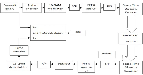
[image:2.595.58.541.451.704.2]The general system used in this paper is shown in Fig. 3. At transmitter, the data bit streams are encoded by a Turbo encoder. The coded bit streams are mapped to a digital modulator, which is 16-QAM. 16-QAM (Quadrature Amplitude Modulation) is used to modulate symbol streams which will converted into parallel output. First, pilot symbol will be inserted corresponding to pilot patterns then symbol sequence in frequency is modulated by inverse Fast Fourier Transform (IFFT) to an OFDM symbol. A cyclic prefix (CP) is inserted to every OFDM symbol to decrease from the delay spread in channel.
Fig 3: Block diagram of transmitter and receiver of MIMO-OFDM with Turbo code
Tran
smit
ter
CP is used to extend the OFDM symbol by copying the last samples of OFDM symbol into its front. The OFDM symbol is converted from parallel to serial and inserted to the Space Time Diversity Encoder. Finally, the data is transmitted. At receiver, the received symbol streams are first go to the Space Time Diversity Combiner, and will converted from serial to parallel sequence. After that, CP is removed from received symbol streams and remaining OFDM symbol is demodulated by FFT. Frequency pilots are extracted from the demodulated OFDM symbol in frequency domain, and fine frequency synchronization and timing are carried out to extract pilots and data symbols accurately. The refined frequency pilots from all the receive antennas are used for channel estimation. The demodulated OFDM symbols are then equalized to detect the received signal, which will be converted from parallel to serial and then demodulated and decoded. For decoder, turbo decoder is used. Finally, the decoded source bit streams are received in data sink. [6]
5.
DETECTION ALGORITHMS
5.1
Zero Forcing (ZF) detector
The ZF detector performs a linear transformation on the received vector by applying the pseudo-inverse of the channel matrix [8]. The equation for this estimator can be given in equation (6).
𝑊𝑍𝐹= 𝐻(𝐻𝐻𝐻)−1 (6)
Where 𝐻𝐻 is the Hermitian transpose of the channel matrix H.
5.2
Minimum Mean Square Error
(MMSE) detector
The MMSE detector is also a linear detector, and the transformation matrix used in this algorithm is that which minimizes the mean square error between the transformed received vector and the transmitted vector [8]. The equation for the MMSE estimator can be given in equation (7).
𝑊𝑀𝑀𝑆𝐸= 𝐻(𝐻𝐻𝐻 +
𝑁𝑜
𝐸𝑠
𝐼)−1 (7)
Where:
𝑁𝑜: is the noise energy.
𝐸𝑠: is the symbol Energy.
𝐼: is an Identity matrix.
6.
SIMULATION RESULTS
The parameters used in the simulation are shown in table 1. Table 1. The parameters used in the simulation
Parameters value
Modulation 16-QAM
IFFT & FFT length 256
Noise model AWGN
Channel model Rayleigh
Code rate 1/2
[image:3.595.319.544.72.242.2]No. of Rx 2 to 100
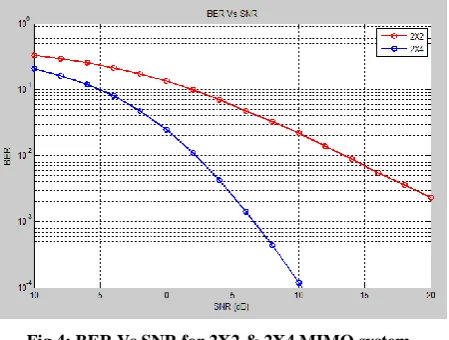
Fig 4: BER Vs SNR for 2X2 & 2X4 MIMO system
[image:3.595.319.551.281.461.2]As the Fig. 4 above shows, the performance of the 2X4 system is much better than the 2X2 system.
Fig 5: BER Vs SNR for 2X4, 2X10, and 2X100 systems
As Fig. 5 shows, the Massive MIMO where 100 antennas used at the receiver shows great performance compared to the other two systems, where it reaches error free performance with SNR value less than -10 dB. Table 2, explains comparision between four different MIMO systems used in the simulation, every system has two transmit antenna.
Table 2. explains the values of SNR to achieve a speceific BER for different number of receive antennas
BER
SNR(dB)
At Nr=2
SNR(dB)
At Nr=4
SNR(dB)
At Nr=10
SNR(dB)
At Nr=100
10-1 2 -5 -10 -21.2
10-2 14 2 -4 -15.1
10-3 22 6.5 -1 -12.4
16 Fig 6: Performance of 2x2 MIMO system with & without
[image:4.595.53.294.75.478.2]turbo coding
[image:4.595.309.547.161.432.2]Fig 7: Performance of 2x4 MIMO system with & without turbo coding
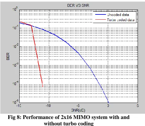
Fig 8: Performance of 2x16 MIMO system with and without turbo coding
Fig.6, fig.7 and fig.8 represent the BER values as a function of SNR for the MIMO-OFDM system for MMSE equalizer with Rayleigh channel. By analyzing these three graphs it is observed that the performance of the system that uses turbo
[image:4.595.55.292.283.473.2]coding is much better than the system which doesn’t use turbo coding. It is observed that turbo-coded MIMO-OFDM provides a gain of 10 dB approximately more than un-coded MIMO-OFDM at BER of 10-3. Table 3, includes the values of SNR for the coded and un-coded MIMO-OFDM system needed to obtain the same BER.
Table 3. explains the values of SNR for the coded and un-coded MIMO-OFDM
BER
2x4 MIMO system 2x16 MIMO system
SNR(dB)
Of coded
SNR(dB)
Of un-coded
SNR(dB)
Of coded
SNR(dB)
Of un-coded
10-1 -7.9 -4.5 -12.9 -11.7
10-2 -7.3 1.3 -12.3 -6.3
10-3 -6.6 4.2 -11.7 -3.5
10-4 -6.1 6.3 -11.1 -1.5
[image:4.595.55.291.504.709.2]17
8.
REFERENCES
[1] J. W. Choi, B. Lee, B. Shim, and I. Kang, “Low Complexity Detection and Precoding for Massive MIMO [2] Systems”, In Wireless Communications and Networking
Conference (WCNC), 2013, pp. 2857 – 2861.
[3] A.Wadday, S. Abdul Aziz, A.S.Abdallah, "Turbo and Convolutional Codes Assisted Space Time Block Code Spatial Modulation" IEEE International Conference on Future Communication Networks, 2012.
[4] Y.S. Cho, J. Kim, W. Y. Yang, C. G.Kang, “MIMO-OFDM Wireless Communications with MATLAB” Book IEEE Press Conference, 2010.
[5] P.Dahiya, K.Sharma, “Turbo coded MIMO-OFDM systems”, International Journal of Engineering and Innovative Technology (IJEIT) Volume 3, Issue 3, September 2013.
[6] S. Kaur, G. Bharti, “Orthogonal frequency division multiplexing in wireless communications systems: A Review” International Journal of Advanced Research in Computer Engineering & Technology Volume 1, Issue 3, May 2012.