55
Stress Field in Functionally Graded Cylindrical
Structures Under Thermo-Mechanical Loading
Bidhneshwar Kumar UpadhyayP 1
P
, Dr. Sanjay MishraP 2
P
1
P
Department of Mechanical Engineering, Madan Mohan Malaviya University of Technology Gorakhpur -273010,Uttar Pradesh,India,Email [email protected] Mobile No-9415778602
P
2
P
Associate Professor, Department of Mechanical Engineering, Madan Mohan Malaviya University of Technology, Gorakhpur-273010,Uttar Pradesh,India.Email [email protected] Mobile
No-9650178116
U
Abstract
By using composite Cylinders Assemblage (CCA) model for a three-phase system consisting of a metallic and ceramic phase joined together by an FGM phase of arbitrary composition (gradation), a generalized formulation for the micro stress analysis of functionally graded cylindrical structure under axisymmetric mechanical and/or thermal loading is presented.FGM phase is divided into an arbitrary number (n) of concentric Cylinder (phase) between metal and ceramics phases. Each of the n concentric FGM phases has different properties in proportion to the average volume fractions of the constituents in that phase. All the phases are assumed to be transversely isotropic with respect to their stiffness and thermal expansion coefficient. Temperature field can be different in each phase, but here only a uniform field has been considered. The formulation presented is expected to be useful in the analysis of cylindrical FGM structure subjected to thermo-mechanical loading.
U
Introduction
In engineering applications, individual elements are exposed to local loading conditions, which can vary greatly with location. In cases, we use different materials such as metal and ceramic. The abrupt transition in microstructure and composition between the different materials often result in high residual stress regions and local stress concentrations which can lead to the subsequent nucleation of micro cracks at or near the biomaterial interface. The intensity existence of the stress concentration effects due to large dissimilarity in properties can be substantially reduced if the microstructure is gradually varied from that of the metal to that of ceramic. Relatively new classes of materials known as functionally graded materials (FGMs) have been developed to minimize such property mismatch effects.
The composition and of an FGM varies with location, resulting in spatially
dependent properties. The composition profile can take different forms depending upon
the required performance. These materials have potential to enjoy a wide range of thermal and structural applications, including thermal gradient structures, wear and corrosion
resistant coatings and metal ceramic joining.
56
thickness or along the plane. Properties may be quite different from one face to the other face of the material. For example, in a metal-ceramic FGM, the metal rich side is typically placed in the regions where mechanical properties, such as toughness, need to be high. In contrast, the ceramic-rich side, which has lower thermal conductivity and can withstand high temperatures, is placed in regions where there are potentially sharp temperature gradients.
The advantages of using FGM as an alternative to two dissimilar materials joined directly together include: smoothing of thermal stress distributions across the layers, minimization or elimination of stress concentrations, increase in biomaterial bonding strength, and improved fracture toughness compared to that of monolithic ceramics, as a result of the plastic deformation of the metallic phase.
Fig.1.Schematic view of three-layered model
U
Applications of FGM and the Present Works:
In case of an artificial implant for a bone, its design changes from a dense, stiff external structure (the cortical bone) to a porous internal one (the chancellors bone). An artificial Hip joint is an ideal example of this kind of structure. Early methods of correcting the diseased or fractured hip joints only involved the ace tabular cup or femoral head. One technique of restoring hip joint function is to place a cup over the femoral head while the surface of the acetabulum is also respected to fit the cup. The implant serves as a mold interposing the two surfaces, which eventually adapt according to the function of the joint. The wide variety of implants reflects the limited knowledge of the function of the joints and the ability of the joint to accommodate any insult imposed upon it by the various implants. Most femoral head replacements are performed with the installation of an ace tabular cup. This is the so-called hip joint replacement, which is frequently performed bilaterally. The various types of hip implants can be grouped into ball and socket, retained ball and socket, turning bearing, and floating acetabulum and double cup.
57
performing a set of specified functions . The properties of material in FGMs are not uniform across the entire material, and the properties depend on the spatial position of the material in the bulk Structure of the material. Functionally graded materials are designed with varying properties that include changing chemical properties, changing mechanical, magnetic, thermal, and electrical properties. There are FGMs that are designed as stepwise-graded structures, and some are designed to be continuous-graded structures, depending on the areas of application .There are different types of areas, in which FGMs are now being used that are different from the initial area of application, for which the material was invented .In this chapter, the different types of FGMs and their areas of application are presented. The different types of FGMs include porosity and pore size gradient structured FGMs, chemical gradient-structured FGMs, and micro structural gradient-structured FGMs. These different types of functionally graded materials are presented in the next sections.
Types of Functionally Graded Materials
• Chemical Composition Gradient Functionally Gradient Materials
• Porosity Gradient Functionally Gradient Materials
• Microstructure Gradient Functionally Gradient Materials
U
Problem Description
A cylindrical structure containing a functionally graded phase sandwiched between a metallic and a ceramic phase has been considered. The composition and microstructure of an FGM varies with location, resulting in spatially dependent properties. The composition profile can take different forms depending upon the required performance. It may be of linear, cubic, parabolic or any arbitrarily varying profile.Analytical solutions are possible only for the linear composition profile or any other profile which can be expressed in functional analytical form. But if there is an abrupt change in the composition with respect to the position or some arbitrary variations exist then it is not possible to obtain analytical solution. So for this kind of arbitrary composition variation in FGM we have developed a new algorithm using a concentric cylindrical assemblage (CCA) model. In this approach we assume the FGM phase as consisting of a number of concentric layers, each one having distinct value of volume fraction. Mechanical properties such as elastic modulus, coefficient of thermal expansion, modulus of rigidity, all depends upon the volume fraction. So each concentric layer of FGM phase has also distinct values of mechanical properties. Thus, the problem is converted into an assemblage of a number of concentric cylinders each with distinct mechanical and thermal property, and bonded perfectly to each other.
U
Problem Formulation
58
fraction. Mechanical properties such as elastic modulus E, coefficient of thermal of thermal
expansion∝, modulus in FGM. So each concentric layer of FGM phase has also distinct values of
mechanical properties. So it is considered that more than one type of concentric phases exists between the central core and the outermost material.
In the CCA model used here, we have taken total P number of concentric circular cylindrical layers. The different phases are: (i) outermost cylinder with the properties of ceramic, (ii) FGM phase having number of concentric layers, (iii) innermost metallic cylinder. These phases are denoted by domain 1,
2, 3… P respectively, and their limiting outermost radii by rR1R, rR2,rRR3R, …………rRpR, respectively.
To make the formulation more general, all these phases, confined between the cylinders, are assumed to be transversely isotropic with regard to their stiffness and thermal expansion
coefficient. The (t,𝜃) plane, which is also the cross-sectional plane of the cylindrical system represents
this transverse plane of isotropy.
Basic Assumptions:
Apart from taking all the phases to be transversely isotropic they are taken to be linearly isotropic. It is also assumed that
• No voids exist in any of the phases,
• A perfect bond exists at the common boundary of the phases,
Boundary Conditions:
The entire system is subjected to three independent boundary conditions;
• Uniaxial applied stress 𝜎Roz,
• Biaxial applied stress 𝜎Ror,Rand
• Axisymmetric temperature change ∆T
Where r and z are respectively, the radial and axial directions referred to cylindrical
coordinates (r, 𝜃,z) shown in Fig.6.
Analytical Derivation:
Referring to Fig.6, for any domain (say nth phase/domain), the stress (𝜎RijR) equilibrium equations may
59 1 𝑟 𝜕 𝜕𝑟(𝑟𝜎𝑟𝑟𝑛) + 1 𝑟 𝜕𝜎𝑟𝜃𝑛 𝜕𝜃 + 𝜕𝜎𝑟𝑧𝑛 𝜕𝑧 − 𝜕𝜎𝜃𝜃𝑛
𝑟 = 0
1
𝑟 𝜕
𝜕𝑟(𝑟2𝜎𝜃𝑟𝑛) +
1
𝑟 𝜕𝜎𝜃𝜃𝑛
𝜕𝜃 + 𝜕𝜎𝜃𝑧𝑛
𝜕𝑧 = 0
1 𝑟 𝜕 𝜕𝑟(𝑟𝜎𝑧𝑟𝑛) + 1 𝑟 𝜕𝜎𝑧𝜃𝑛 𝜕𝜃 + 𝜕𝜎𝑧𝑧𝑛
𝜕𝑧 = 0
……… (1)
Throughout the text, a superscript n or n in the subscript will represent the nth phase. Treating the domain to be transversely isotropic, the stress-strain relations are
⎣ ⎢ ⎢ ⎢ ⎢ ⎢ ⎡𝜎𝜎𝑟𝑟𝑛 𝜃𝜃𝑛 𝜎𝑧𝑧𝑛 𝜎𝜃𝑧𝑛 𝜎𝑧𝑟𝑛 𝜎𝑟𝜃𝑛 ⎦ ⎥ ⎥ ⎥ ⎥ ⎥ ⎤ = ⎣ ⎢ ⎢ ⎢ ⎢ ⎡
𝑐11𝑛 𝑐12𝑛 𝑐13𝑛
0 0 0
𝑐12𝑛 𝑐11𝑛 𝑐13𝑛
0 0 0 𝑐13𝑛 𝑐13𝑛 𝑐33𝑛
0 0 0 0 0 0
𝑐44𝑛
0 0 0 0 0 0
𝑐44𝑛
0 0 0 0 0 0
𝑐11𝑛−𝑐12𝑛 2 ⎦ ⎥ ⎥ ⎥ ⎥ ⎤ ⎣ ⎢ ⎢ ⎢ ⎢ ⎢ ⎡𝑒𝑒𝑟𝑟𝑛 − 𝛼𝑛𝑇𝑛 𝑇𝑛 𝜃𝜃𝑛 − 𝛼𝑛𝑇𝑛 𝑇𝑛 𝑒𝑧𝑧𝑛 − 𝛼𝑛𝑇𝑛 𝑇𝑛
2𝑒𝜃𝑧𝑛
2𝑒𝑧𝑟𝑛
2𝑒𝑟𝜃𝑛 ⎦⎥ ⎥ ⎥ ⎥ ⎥ ⎤
This can alternatively be written in the form
𝜎𝑟𝑟𝑛 = 𝐶11𝑛𝑒𝑟𝑟𝑛 + 𝐶12𝑛 𝑒𝜃𝜃𝑛 +𝐶13𝑛𝑒𝑧𝑧𝑛 − 𝛾1𝑛𝑇𝑛
𝜎𝜃𝜃𝑛 = 𝐶
12𝑛 𝑒𝑟𝑟𝑛 + 𝐶11𝑛𝑒𝜃𝜃𝑛 +𝐶13𝑛𝑒𝑧𝑧𝑛 − 𝛾1𝑛𝑇𝑛
60 𝜎𝜃𝑧𝑛 = 2𝐶44𝑛𝑒𝜃𝑧𝑛
𝜎𝑧𝑟𝑛 = 2𝐶44𝑛2𝑒𝑧𝑟𝑛
𝜎𝑟𝜃𝑛 = (𝐶
11𝑛 − 𝐶12𝑛)𝑒𝑟𝜃𝑛 ……….. (2)
Where
𝛾1𝑛 = (𝐶11𝑛 +𝐶12𝑛 )𝛼𝑛𝑇𝑛 +𝐶13𝑛𝛼𝑛𝐿𝑛
𝛾3𝑛 = 2𝐶13𝑛𝛼𝑛𝑇𝑛 +𝐶33𝑛𝛼𝑛𝐿𝑛 ….. (3)
eRijR and CRijR and are respectively, strain components and the elastic constants. ∝RnTR and ∝RnLR are the
coefficient of thermal expansion in transverse and longitudinal direction respectively. Due to ax
symmetry, the displacement field (uRiR) in the n-th domain can be expressed as
𝑢𝑟𝑛 =𝑢𝑛(𝑟)
𝑢𝜃𝑛 = 0
𝑢𝑧𝑛 =𝑤𝑛(𝑧) ………. (4)
This consequently gives
𝑒𝑟𝑟𝑛 =𝜕𝑢𝑛 𝜕𝑟
𝑒𝜃𝜃𝑛 =𝑢𝑛 𝑟
𝑒𝑧𝑧𝑛 =𝜕𝑤𝑛
𝜕𝑧 , and
𝑒𝑧𝑟𝑛 =𝑒𝜃𝑧𝑛 =𝑒𝑟𝜃𝑛 … ……….. (5)
The stress-strain relations expressed in Equations (2) are now written, using equation (5), as
𝜎𝑧𝑧𝑛 = 𝐶13𝑛 𝜕𝑢𝜕𝑟𝑛 + 𝐶13𝑛 𝑢𝑟𝑛+𝐶33𝑛 𝜕𝑤𝜕𝑧 − 𝛾𝑛 3𝑛𝑇𝑛
𝜎𝑟𝑟𝑛 =𝐶11𝑛 𝜕𝑢𝑛𝜕𝑟 + 𝐶12𝑛 𝑢𝑛𝑟 +𝐶13𝑛 𝜕𝑤𝑛𝜕𝑧 − 𝛾1𝑛𝑇𝑛
𝜎𝜃𝜃𝑛 =𝐶
12𝑛 𝜕𝑢𝑛𝜕𝑟 + 𝐶11𝑛 𝑢𝑛𝑟 +𝐶13𝑛 𝜕𝑤𝑛𝜕𝑧 − 𝛾1𝑛𝑇𝑛
61
……….. (6)
From equation (1) and (6), the governing differential equations are then obtained in terms of displacements in the form:
𝜕2𝑢𝑛 𝜕𝑟2 +
1 𝑟
𝜕𝑢𝑛 𝜕𝑟 −
𝑢𝑛 𝑟2 = 𝐾𝑛
𝜕𝑇𝑛 𝜕𝑟
………… (7)
𝜕2𝑤𝑛
𝜕𝑧2 = 0 … ……. (8)
With
𝐾𝑛 = 𝛾1𝑛⁄𝐶11𝑛
The boundary conditions and continuity conditions of stresses and displacements at the interfaces of the concentric cylinders (phases) are given as the following
𝜎𝑟𝑟1 = 𝜎0𝑟 𝑟=𝑟1 … … . (9)
𝜎𝑟𝑟2 =𝜎𝑟𝑟1 ,𝑢1 =𝑢2,𝑤1 =𝑤2 𝑎𝑡 𝑟= 𝑟2 … . (10)
𝜎𝑟𝑟3 = 𝜎𝑟𝑟2 ,𝑢2 =𝑢3,𝑤2 = 𝑤3 𝑎𝑡 𝑟= 𝑟3 … . (11)
𝜎𝑟𝑟𝑖 =𝜎𝑟𝑟𝑖+1,𝑢𝑖 =𝑢𝑖+1,𝑤𝑖 =𝑤𝑖+1 𝑎𝑡 𝑟=𝑟𝑖+1 𝑓𝑜𝑟 𝑖 = 1 𝑡𝑜 (𝑝 −1)
… . (12)
� 𝜎𝑧𝑧𝑝 𝑝
0 𝑟𝜕𝑟+� 𝜎𝑧𝑧 𝑝−1 𝑟𝑝−1
𝑟𝑝
𝑟𝜕𝑟+⋯… … +� 𝜎𝑧𝑧𝑖−1 𝑟𝑖−1
𝑟𝑖 𝑟𝜕𝑟+⋯… . +� 𝜎𝑧𝑧 1 𝑟1
𝑟2
𝑟𝜕𝑟 =� 𝜎0𝑧 𝑟1
0 𝑟𝜕𝑟
… … . (13)
General solution to equation number (7) and (8) can be given as;
𝑢𝑛(𝑟) =𝐴𝑛𝑟+𝐵𝑟𝑛+𝑟𝑆𝑛(𝑟) +1𝑟 𝐷𝑛(𝑟)
………. (14)
𝑤𝑛(𝑧) =𝐸𝑛𝑧+𝐹𝑛
… … … (15)
Where ARn, RBRn, RERnR and FRnR are unknown constants to be determined by utilizing the boundary conditions,
and
𝑓𝑛(𝑟) =𝐾𝑛𝜕𝑇𝜕𝑟𝑛
𝑆𝑛(𝑟) =12� 𝑓𝑛(𝑟)𝜕𝑟,
62
It may be noted that in case of Tn being a constant (i.e., not a function of r) over the domain (phase) n,
fn will be zero and consequently, SRnR (r) and DRnR (r) also become zero.
The constant FRnR in equation (15) can be made zero because a constant value of it would mean a
rigid body displacement in the z-direction, i.e,
𝐹1 =𝐹2 = ⋯… … … . =𝐹𝑃 = 0
Now by using the boundary conditions, i.e. the condition of continuity in equation number (15), gives
𝐸1 = 𝐸2 = 𝐸3 =……=𝐸𝑃 =𝐸
Therefore, equation (15) yields
𝑤1(𝑧)=𝑤2(𝑧)=……….𝑤𝑝(𝑧) =𝐸𝑧 … … . . (16)
Where E is a constant. Now substituting the expression (14) and (15), into equation (1) gives
𝜎𝑟𝑟𝑛 =𝐶11𝑛[𝐴𝑛−𝐵𝑟𝑛2+𝑆𝑛(𝑟)− 1
𝑟2𝐷𝑛(𝑟)]+𝐶12𝑛[𝐴𝑛+ 𝐵𝑛
𝑟2+𝑆𝑛(𝑟) 1
𝑟2𝐷𝑛(𝑟)]
+𝐶13𝑛𝐸 − 𝛾1𝑛𝑇𝑛(𝑟)
𝜎𝜃𝜃𝑛 =𝐶
12𝑛[𝐴𝑛−𝐵𝑟𝑛2 +𝑆𝑛(𝑟)− 1
𝑟2𝐷𝑛(𝑟)]+𝐶11𝑛[𝐴𝑛 + 𝐵𝑛
𝑟2 +𝑆𝑛(𝑟) 1
𝑟2𝐷𝑛(𝑟)]
+𝐶13𝑛𝐸 − 𝛾1𝑛𝑇𝑛(𝑟)
𝜎𝑧𝑧𝑛 = 2𝐶13𝑛[𝐴𝑛+𝑆𝑛(𝑟) +𝐶33𝑛𝐸 − 𝛾3𝑛𝑇𝑛(𝑟)
… … … . . (17) Thus, for getting the stresses and displacements in all the P-phases through equations (14),(16) and (17), (2p+1) Constants (p values of each An and Bn, and e) must be determined. Since the radial displacement at the center of the core (i.e., Up (o)) cannot be in finite, Bp must be zero. Therefore only 2p constants are left which are determined with the help of the boundary conditions. Equations (10),(11) and (12) furnish a total of 2(p-1) Conditions. The remaining two Conditions needed for Finding out the values of 2p constants are given be Equations (9) and (13). Thus substitution of the Expression of radial displacement at from Equations (14) into Equations (10),(11)and (12), and stress Equations (17) into Equations (9) and (13) gives a set of 2p simultaneous Equations, which can be put in a Matrix form
�𝑎𝑖𝑗��𝐴1,𝐴2,𝐴3,𝐴4, … .𝐴𝑃,𝐵1, … .𝐵𝑝−1,𝐸�=
⎝ ⎜ ⎛
𝑏1 𝑏.2
..
𝑏2𝑝⎠ ⎟ ⎞
………. (18)
In the matrix equation (18) the first (p-1) equations correspond to continuity of displacement
conditions (10)… (12), pP
th
P
63
stress. The next (p-1) equations came through the condition of continuity of the radial stress. The last
(2pP
th
P
) equation results from the balancing of the axial forces using equation (13). In fact, by applying
the conditions in this order, the elements of the square matrix [aRijR] and the vector {bRijR}are observed to
follow a definite pattern and the matrix expands in a particular manner as the number of phases (p) increases.
Particular Case:
Some of the non-zero coefficients of the matrices [aij] and {bij} given above, get further simplified for the case when we take material as isotropic and a constant temperature over entire
structure. So it is obvious that for TRnR being constant value (i.e., not a function of radius) for the entire
phase n,
𝑆𝑛 = 𝐷𝑛 =𝑃𝑛=𝑄𝑛 =0
This simplifies the stress equation (17) as
𝜎𝑟𝑟𝑛 = 𝐶11𝑛(𝐴𝑛−
𝐵𝑛
𝑟2) +𝐶12𝑛(𝐴𝑛+
𝐵𝑛
𝑟2) +𝐶13𝑛𝐸 − 𝛾1𝑛𝑇𝑛
𝜎𝜃𝜃𝑛 =𝐶
12𝑛 �𝐴𝑛−
𝐵𝑛
𝑟2�+𝐶11𝑛 �𝐴𝑛+
𝐵𝑛
𝑟2�+𝐶13𝑛𝐸 − 𝛾1𝑛𝑇𝑛
𝜎𝑧𝑧𝑛 = 2𝐶13𝑛𝐴𝑛 +𝐶33𝑛𝐸 − 𝛾3𝑛𝑇𝑛
The displacement equations (14) and (15) become
𝑈𝑛(𝑟) =𝐴𝑛𝑟+𝐵𝑟𝑛
𝑊𝑛(𝑧) =𝐸𝑧
In the matrix equation (18) the coefficient of (𝑏𝑖𝑗), get simplified as
𝑏1 =0 𝑓𝑜𝑟𝑖=1𝑡𝑜 (𝑝 −1)
=𝜎𝑜𝑟+𝛾11T for i=p
=(𝛾1𝑖−𝑝− 𝛾1𝑖−𝑝+1)𝑇 𝑓𝑜𝑟𝑖= (𝑝+1)𝑡𝑜(2𝑝 −1)
=𝜎𝑜𝑧𝑟12+∑𝑝𝑗=1𝛾3𝑗𝑇�𝑟𝑗2− 𝑟𝑗+2 1� 𝑓𝑜𝑟 𝑖=2𝑝
Here we have assumed that material is isotropic, so
𝐶11𝑛 =𝐶22𝑛 =𝐶33𝑛
and
𝐶12𝑛 =𝐶13𝑛
𝐶44𝑛 =
𝐶11𝑛 − 𝐶12𝑛
64 𝐶11𝑛 =
(1− 𝑣𝑛)𝐸𝑛
(1+𝑣𝑛)(1−2𝑣𝑛)
𝐶12𝑛 =
𝑣𝑛𝐸𝑛
(1+𝑣𝑛)(1−2𝑣𝑛)
Here the volume fraction of metallic core 𝑉𝑚 and ceramic layer 𝑉𝑐 can be given as
𝑉𝑚 = (𝑟𝑟𝑝1)P
2
𝑉𝑐 =1-(𝑟𝑟21)P
2
Where,
rp =radiusofmetaliccore
r1 =radiusoftheceramicphase
r2 = EffectiveradiusoftheFGMphase
U
Description of the Cylindrical FGM System
The analytical formulation developed in the previous chapter has been demonstrated to find out the internal micro-stresses developed in the functionally graded cylindrical structure when it is subjected to the mechanical loading, thermal loading or the combination of both kinds of loadings. Results have been shown through figures for different combinations of the loadings.
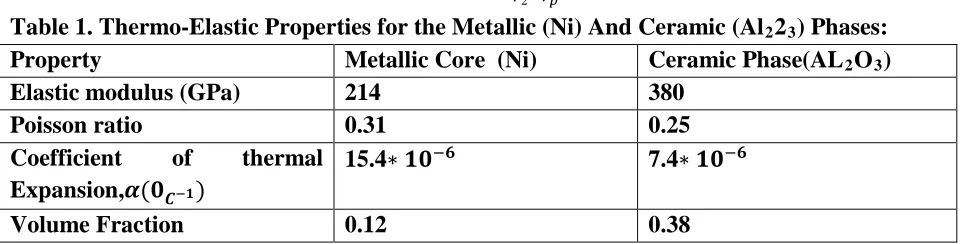
In our particular case we have taken the cylindrical system of Ni-FGM-A1R2ROR3R with all the
phases assumed to be isotropic, free of damage and having the temperature independent properties
given in the Table 1. A constant temperature of 300P
o
P
C is considered throughout the region. Here we have assumed a linear profile of the gradation of the properties in the functionally graded phase.
The compositional gradation of FGM is defined by the volume fraction of the ceramic phase. Let the volume fraction of the ceramic material within the FGM vary as a function of the coordinate, r, and be arbitrarily defined by a generic function, V (r) which satisfies the following conditions at the interfaces which the FGM makes with homogeneous phases on its two sides.
V(r) =�0
1 𝑎𝑡𝑟 =𝑟𝑝 𝑎𝑡𝑟 =𝑟2
The elastic properties of the FGM in concentric cylinder (phases) n is given by its Young’s
modulus, ERnR, and Poisson’s ratio, vRnR , together with the coefficient of thermal expansion, aRnR. These are
assumed to vary according to the rule of mixture. Then,
𝐸𝑛(𝑟) =𝐸2+ (𝐸1 − 𝐸2)𝑉(𝑟)
𝑣𝑛(𝑟) =𝑣2+ (𝑣1− 𝑣2)𝑉(𝑟)
𝛼𝑛(𝑟) =𝛼2+ (𝛼1− 𝛼2)𝑉(𝑟)
65
V(r) =(𝑟−𝑟𝑝
𝑟2−𝑟𝑝)
Table 1. Thermo-Elastic Properties for the Metallic (Ni) And Ceramic (AlR2R2R3R) Phases:
Property Metallic Core (Ni) Ceramic Phase(ALR2ROR3R)
Elastic modulus (GPa) 214 380
Poisson ratio 0.31 0.25
Coefficient of thermal Expansion,𝜶(𝟎𝑪−𝟏)
15.4∗ 𝟏𝟎−𝟔 7.4∗ 𝟏𝟎−𝟔
Volume Fraction 0.12 0.38
Here we assume that radius of the metallic core rRpR is 4 mm. We have shown the results
for bi-axial loading, uniaxial loading and for thermal loading by taking different number of concentric cylinders in FGM phase.
Value of uniaxial applied stress= 3.65 GPa Value of Biaxial applied stress=2.63 GPa
U
Results and Discussion
Firstly, some solutions are obtained for the bi-axial loading conditions when properties of both the inner and outer cylinders are taken to be identical so that the system works as a solid cylinder. Values of the radial and circumferential stresses are found to be equal to the external applied load, and also would be uniform throughout the region. We can see that the value of axial stress is zero.
To demonstrate the effect of number of phases ‘p’ in which FGM is divided, results have been shown for p=12 and p= 100. The FGM phase should be divided into a large number of concentric cylinders to get smooth and converging value of stresses. For the case of bi-axial loading at the outer surface of the assembly, stress variations are shown for the radial, circumferential and the axial component of the stresses. the stresses developed in the axial direction are of significance. Its value in the metallic core takes a constant negative value and also in some of the FGM region it is negative while in the region closer to the ceramic phase it becomes positive. In case of unidirectional axial loading only tensile stresses develop.
U
References
• Busso.E.P.“Oxidation-Induced stress in Ceramic-metal Interfaces”.J.Phys.IV,pp.287-296.
• Busso.E.P.,Lin,J. and S.Nakayama,M.”A Mechanistic Study of Oxidation-Induced
Degradation in a Plasma Sprayed Thermal Barrier Coating System.Part I Model Formulation”.Acta Mater 49/9.pp.1515-1529.
• Busso.E.P.,Lin,J. and S.Nakayama,M.”A Mechanistic Study of Oxidation-Induced
Degradation in a Plasma Sprayed Thermal Barrier Coating System.Part II Life Pridiction Model”.Acta Mater 49/9.pp. 1529-1536.
• Christensen, R.M. and Lo,H.,“Solutions for Effective Shear Properties in Three-Phase Sphere
66
• Finot M. and Suresh,S., “Small and Large Deformation of Thick and Thin Multi-Layer
Geometry, Plasticity and Compositional Gradients”.J.Mech.Phys Solids 44(5),pp.683-721.
• Ferund ,L.B., “Stress Distribution and Curvature of a General Compositionally Graded
Semiconductor Layer”. J.Crystal Growth 132(1-2),pp341-344.
• Ginnakopouds .A.E., Suresh.S. and Finot,M. and Olsson,M., “ Elasto Plastic Analysis of the
Thermal Cycling ;Layered Materials with Compositional Gradients”.Acta Metall. Meter 43(4),pp.1335-1354.
• Iesan,D., “ Thermal Stresses in Composite Cylinders,” J.Thermal Stress,Vol.3,pp.495-508.
• Ishikawa,T.,Koyama,K.and Kobayashi,S., “Thermal Expansion Cofficient of Unidirectional
Composites,” J.Comp.Mater., Vol.12, pp.153-166.
• Lee.Y.D., and Erdogm,F., “ Residual/Thermal Stresses in FGM and Laminated Thermal
Barrier Coatings”.Int. J.Fract.69,pp.145-165.
• Mikata,Y.and Taya, M., “The Stress Field in and Around a coating in a Coated Short Fiber
Composite Subjected to Uniaxial and Biaxial Loading,” J. Appl.Mech.,Vol.52,pp19-24.
• Mikata,Y.and Taya, M., “Thermal Stresses in a Coated Short Fiber Composite,” submitted for
publication.
• Olsson .M., Ginnakopouds. A.E. and Suresh. S., Elastoplastic Analysis of Thermal Cycling :
Ceramic Particles in a Matellic Matrix”. J Mech. Phys. Solids 43(10),pp.1639-1671.
• Takeuchi, Y., Furukawa,T. and Tanigawa, Y., “The Effect of Thermoelastic Coupling for
transient Thermal Stresses in a Composite Cylinder,” ASME,WAM,DE-2.
• Wessenbek.E., Pettermann. H.E and Suresh.S “Elasto-Plastic Deformation of Compositionally
Graded Metal-Ceramic Components”. Acta.Mater.45(8) pp.3401-3417.
• Upadhyay,P.C. and Lyons,Jed S., “ Stress Field in Continuous Fiber Reinforced Composites
with Multiple Interfacial Layers,” J. Reinforced Plastics and Composites, Vol.18, pp.1630-1644.
• Uemura, M., Iyama, H. and Yamagauchi, Y., “Thermal Residual Stress in Filament Wound