20th International Conference on Structural Mechanics in Reactor Technology (SMiRT 20) Espoo, Finland, August 9-14, 2009 SMiRT 20-Division 6, Paper 1972
1
Structural Analysis Design and Detailing of Reactor Vault in Prototype Fast
Breeder Reactor
K V Subramanian
1, S M Palekar
1, H A Mapari
1, R Balaji
11
TCEConsulting Engineers Ltd, Mumbai, India, e-mail: [email protected]
Keywords: Reactor Vault, Fast Breeder Reactor, Liners, Seismic Analysis
1
ABSTRACT
Prototype Fast Breeder Reactor (PFBR) is the first Reactor of its kind presently under construction at Kalpakkam in INDIA. Reactor Assembly in Reactor Containment Building (RCB) of PFBR comprises of a main vessel with the core and a concentrically placed Safety vessel, both supported from (hanging from) two concentric Cylindrical Reinforced Concrete (RC) walls which constitute the Reactor Vault.
This paper describes various issues pertaining to Structural analysis, design of walls forming the Reactor Vaults and Reactor Assembly with Main and Safety vessels (together called as RA system in this paper), and its detailing and construction-related issues. Modeling to simulate exact behavior of the RA system, requirement for structural analysis (Static and Seismic) under different conditions of the RA system including leakage of Main Vessel (MV), overflow of Sodium from Main Vessel - Safety Vessel inter-space, and the necessity to couple the structural behavior of RA system with rest of the integrated power plant structure, forms an important feature in the analysis. Refined sub-modeling has been used for performing the analysis and design of certain critical portions of RA system (using 3-D brick elements).
Analysis of the walls for Heat of Hydration load has been performed as a construction-stage analysis using a Time-History based methodology as elaborated in this paper.
Considerations of constructability and appropriate detailing techniques have been identified.
2
INTRODUCTION
The Reactor Vault housed in the Reactor Containment Building (RCB) form a major structural system. This
Building forms one of the buildings constituting the Nuclear Island Connected Building (NICB), an integrated
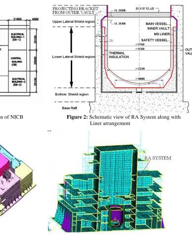
structure constituting of eight buildings, viz Reactor Containment Building (RCB), Steam Generator Buildings (SGB1 & SGB2), Fuel Building (FB), Rad Waste Building (RWB), Electrical Buildings (EB1 & EB2) and Control Building (CB) integrated to form a single integrated structural system. Figure 1 shows plan of NICB with eight constituting Buildings.
The Reactor Vault (RV) in RCB comprises of two concentric cylindrical reinforced concrete walls (RC walls) separated by 50mm annular gap containing thermal insulation both vertically and below the base slab of the RV. The Reactor Assembly (comprising of Reactor Vessel and the core) hangs from the outer wall and a Safety Vessel hangs from the inner wall of the vault. The walls of the Reactor Vault and the Reactor Assembly (with Main and Safety vessels) form the RA System. Figure 2 shows the General arrangement of the RA System. The inner wall is lined with metallic liner and Biological Shield Cooling System (BSCS) provided behind the liner, is the cooling system to control the concrete temperatures of the Inner wall. The Safety Vessel (SV) provided outside the Main Vessel (MV) acts as a barrier against sodium leakage from MV. A roof slab provided for the Reactor Assembly, forms the support for different equipments / operating platforms.
2
Figure 1: General Plot Plan of NICB Figure 2: Schematic view of RA System along with Liner arrangement
Figure 3: 3-D Model of NICB Figure 4: Cross Sectional view of 3-D FE Model of NICB showing RA system
3.
DESCRIPTION OF THE STRUCTURE
3
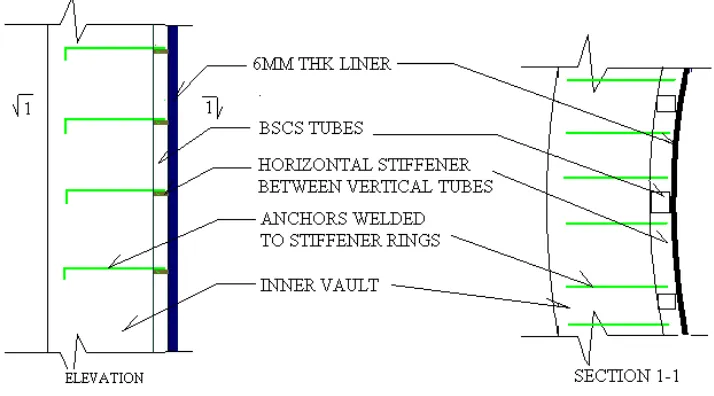
The IV is lined by a metallic liner on the inner side to prevent the IV concrete coming in contact with any sodium that may spill over into IV from SV-IV inter-space. The liner is provided with ring stiffeners and anchors which are embedded into IV concrete. IV is provided with a Biological Shield Cooling System (BSCS), which comprises of a set of longitudinal tubes welded to the back-side of the liner. (Fig. 5). Cooling water circulated through the BSCS tubes maintain the temperature of concrete of IV within acceptable limits so as to prevent material degradation. The Outer wall of the Reactor Vault (OV) forms the last barrier of the RA system.
IV and OV behave as structurally independent systems separated by Expanded Poly-Styrene (EPS), 50mm thick. OV is integral with base slab (Raft) of NICB. IV is supported at its base in such a manner that it allows radial thermal expansion (Figure 6). The supporting arrangement comprises of a central pedestal that is fully integral with the base slab and eight numbers of peripheral Bearing Plates (BP) with a sliding-mirror finish and that permits radial expansion of IV.
.Figure 5: Supporting Arrangement of Liner in IV and details of BSCS
Figure 6: Supporting Arrangement for IV base
4
Figure 7: Typical Support Detail for MV / SV4.
STRUCTURAL ANALYSIS AND DESIGN OF RA SYSTEM
The RA System is to be designed under the normal operating condition and various assumed conditions of
leakage of sodium. Analysis methods adopted under these conditions are described below.
4.1 Inner and Outer walls of Reactor Vault
4.1.1 Normal operating condition
Under this condition, the RA system is coupled with the Global FE model of NICB (Figure 4). The MV is filled with Sodium and SV-MV inter-space filled with Nitrogen. In the Global model, MV, SV, IV and OV are modeled with thick shell elements (with out-of-plane shear deformation capability). Connection between different parts is achieved using rigid links with appropriate Degrees of Freedom (DOF) released, to simulate the actual physical behavior. Mass of filled Sodium is modeled by lumping equivalent impulsive, convective and static masses over the inner surface of MV walls at appropriate levels. Static and Seismic analysis of NICB under Normal operating condition is performed based on the Coupled Global model.
4.1.2 Sodium leakage into SV
Under this condition, the RA system is analyzed and designed for an assumed condition of leakage of sodium in the MV into the inter-space between MV and SV. While the static and dynamic behavior of MV and OV are not significantly affected due to the sodium leakage in the SV with respect to Normal operating condition, the sodium occupying the inter-space between MV and SV results in increased seismic and static forces being transmitted to SV support and affect the dynamic behavior of SV and IV. A sub-model of RA system has been used for analysis under this condition. The sub-model comprising of IV, OV and MV and SV is extracted from the Global Model. In addition to the liquid sodium lumped in MV as described above, the portion of sodium mass occupying the volume of inter-space between SV and MV is lumped over the walls of SV. Seismic analysis under this condition gives a conservative estimate of the seismic forces transferred at SV support. The SV support arrangement is designed for the additional static and seismic forces transferred.
4.1.3 Heat of hydration analysis of OV&IV
5
The expression for heat generation rate per unit volume qv is associated to adiabatic temperature rise.
The equation of adiabatic temperature rise with time can be written after Machida et.al as
Ta = K (1-e-αt) (ºC ) (1)
The expression for heat generation rate per unit volume is,
qv = (1/24)ρc αK e-(αt/24) (2)
On the basis of experience and experimental results, Machida et.al. have proposed, for concrete with cement content of 266 kg/m3, the value of K and α as 40.8 oC and 1.6 respectively. In the present analysis the value of Ta thus obtained has been modified proportionately for the cement content of 400kg/m3, (N45) by
multiplying with (400/266) = 1.504
Values of the various parameters considered are,
Thermal Conductivity in concrete, k = 1607 cal/m/hr/oC
Mass Density of concrete, ρ = 2548 kg/m3
Specific Heat of concrete, c = 231.231 cal/kg/oC
Convection film coefficient, h = 10,000 cal/m2/hr/oC
(Air-convection Coefficient)
Ambient Gas / Air Temperature = 35 oC
Concrete Pour temperature = 23 oC
Results of the above analysis did not indicate any additional requirement of reinforcement apart from the provisions for strength and serviceability requirements. The results of Heat-of-Hydration analysis are also used to determine the pour temperature suitable for different pours.
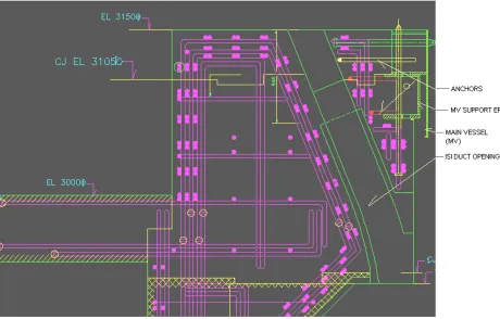
4.1.4 Refined analysis of projecting bracket supporting MV
The projecting portion of OV supporting the MV is 2.24m thick. The static and seismic forces from MV are transferred into this zone. To enable appropriate detailing of reinforcement the variation of stresses across this zone is determined. This zone comprises of supporting EP of MV and supported flange from MV ( Figure 7) embedded into concrete by means of anchors, a vertical tie rod (which would act in releasing energy under Core Disruptive Accident (CDA) condition), and other embedded service pipes.
6
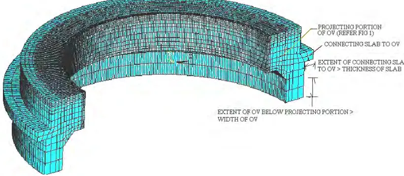
The 3-D model adopted is a half-circular model with RC portions modeled using brick elements. The vertical tie rod (for energy release under CDA), has been modeled. While the steel EPs and flanges have not been modeled, the bearing forces transferred by the bearing plates of EP and flange have been applied at appropriate locations as radially varying loads. The static/seismic deformations of the Global Model are imposed at the base of the sub-model and at the far-end of the portion of connected slab modeled. For this sub model, the extent of OV modeled below the projected portion and that of connected slab are shown in figure 8. The static and seismic loads transferred from MV are applied at appropriate location of EP in the direction pertaining to the load. Seismic forces generated due to inertia of the portion modeled have been applied as body force in the model.
The forces obtained in the nodes of the brick elements have been integrated along vertical and horizontal directions to obtain net force and moment across different vertical and horizontal sections. For the set of forces and moments obtained for a section, design of the section is performed to obtain the total reinforcement required. Totally 80 vertical sections have been identified at various Y co-ordinates (theta), in-order to cover the entire half model. Each section is designed for all the load combinations (as per provisions of code AERB/SS/CSE-1) to determine the reinforcement required to be provided, and the maximum requirement is provided in a circumferentially symmetric way throughout the structure. Design is performed for strength and crack-width based requirements.
4.2 Liner system
The IV and liner are modeled using an axi-symmetric model (Figure 9). IV and liner are modeled parallel to each other and connected at anchor locations by means of rigid links.
The principal design condition for the liner is the thermal gradient across IV and thermal load on liner. These are applied directly as body loads in the axi-symmetric model acting in combination with the vertical static and seismic loads.
Figure 9: Axi-symmetric line model of Liner and IV.
7
Anchorages are determined based on the forces obtained in the rigid links in the above model, along with the anchor forces determined due to hoop strain acting.
The event of over flow of sodium from SV-MV inter-space into the inter-space between SV and Inner wall is considered, and is taken care of by pressure due to sodium applied on the liner.
Other design conditions considered for liner includes design for assumed condition of failure of alternate anchors, and action of Green concrete pressure on liner.
5 CRITICAL ANALYSIS RESULTS
Considering SV and IV moving together, the dynamic results have been compared under leaked and un-leaked conditions, as furnished below (Table 1). This shows the effect of sodium leakage into SV on the dynamic behavior of SV and IV.
Table 1.
Comparison of SV-IV Dynamic behavior under leaked and un-leaked conditions
S.No Condition Mode Freq (Hz) Component participated
Modal mass (t)
1 10.4374 IV + SV 1008.01
1 No sodium
Leak 2 10.4488 IV + SV 621.43
1 14.1192 SV 18.32
2 No sodium
Leak 2 14.1271 SV 14.68
1 7.5703 IV 978.46
3 Leaked
case 2 7.5755 IV 617.76
1 4.7635 SV 632.283
4 Leaked
case 2 4.7664 SV 521.978
The change in the dynamic characteristics under the two conditions is significant.
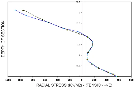
To validate the Half-circular model generated for projecting portion of OV, the stress results obtained in a c/s adequately away from the supports were compared with the stress results obtained based on a axi-symmetric model of the portion. Comparison of stress results under Dead load condition is presented below (Figure 10),
8
6 CONSIDERATIONS FOR CONSTRUCTIBILITYThe challenge in detailing lies in cautious placement of different embedded components of the system in such a manner that they do not interfere with each other and adequate inter-space is available for concreting to the desired quality. Special provisions incorporated to facilitate construction are given below.
In the lower lateral region (Refer figure 5), in-order to accommodate the BSCS an increased concrete cover of 100mm is provided on the inner face of IV.
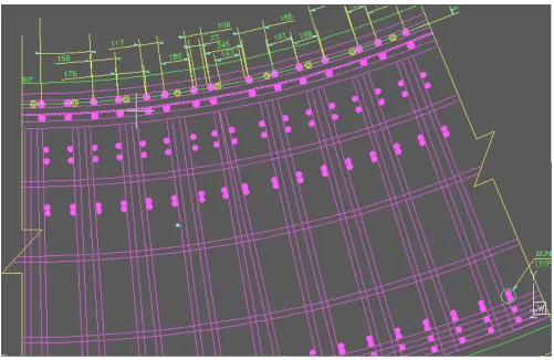
The upper lateral region is critical with respect to detailing, due to presence of heavy reinforcement, along with BSCS pipes and headers, liner and its anchorage and supporting EP and its anchorages. A typical section and plan at upper lateral region (figure 11&12) of OV showing interference check performed and reinforcement detailing prepared, is furnished. A minimum clear spacing of 73 mm between the reinforcement bars has been achieved.
Mock-up for the area shown has been performed and learning utilized during actual concreting.
Detailing the base supporting arrangement for IV required special attention. The Bearing Plates (BPs) (Fig 6) are required to have a mirror finish to allow smooth sliding under thermal loads, and retain this property for the life span of the structure. Manganese Phosphate coating is applied over the BPs to establish the above. However, the anchorages for the BPs are designed to take up a shear force that would get generated with a maximum expected coefficient of friction of 0.3 in the life span of the structure between the butting plate surfaces. The base slab is also designed for taking up tensile force and moment that will be transferred due to frictional resistance that may get developed between the BP surfaces.
9
Figure 12: Typical Plan of Projecting Portion of Outer wall of Reactor Vault Showing Reinforcement Provided
7 CONCLUSION
Appropriate design methods for the RA system to deal with various design conditions have been brought out in this paper. Structural analyses to cater for different components of the system, requiring development of different sub-models apart from Global model have been brought out. Considerations for detailing at critical locations with all the services, anchorages and heavy reinforcement in place to achieve desired quality have been outlined.
Acknowledgement
The authors thank TCE Consulting Engineers and Indira Gandhi Centre of Atomic Research for the constant encouragement received and having accorded permission to publish this paper.
REFERENCES
AERB Safety Standard No. AERB/SS/CSE-1. 2001. Design of Concrete Structures Important To Safety of Nuclear Facilities. Atomic Energy Regulatory Board of India.
AERB Safety Standard No. AERB/SS/CSE-2. 2001. Design Fabrication and Erection of Steel Structures Important To Safety of Nuclear Facilities, Atomic Energy Regulatory Board of India.