ISSN(Online): 2320-9801 ISSN (Print): 2320-9798
I
nternational
J
ournal of
I
nnovative
R
esearch in
C
omputer
and
C
ommunication
E
ngineering
(An ISO 3297: 2007 Certified Organization)
Vol. 3, Issue 5, May 2015
Design of Modified Three Stage Sharpened
CIC Filter for Decimation
Sukhpreet Singh
1, Tripatjot Singh Panag
2M. Tech. Student, Dept of ECE, BBSBEC, Fatehgarh Sahib, Punjab, India1
Assistant Professor, Dept of ECE, BBSBEC, Fatehgarh Sahib, Punjab, India2
ABSTRACT: This paper presents the design of Sharpened three stage CIC filter for decimation. The proposed
decimation filter has Cascaded-Integrator Comb filter as first stage, Sharpened Cascaded-Integrator Comb filter as second and third stage. The CIC filter at first stage operates at input sampling rate, sharpened second stage operates at lower rate as compared to first stage and sharpened third stage operates at lower rate as compared to first as well as second stage. The sharpened second and third stage leads to improvement in pass-band droop and better stop-band alias rejection. Further the reduction of sampling rate at each stage provides many additional benefits like better power efficiency, reduced hardware requirements, reduced cost and better speed. The proposed filter is designed and simulated in MATLAB-Simulink environment. The simulation results and their comparison shows that the proposed decimation filter has improved pass-band droop and better stop-band alias rejection than the existing structures.
KEYWORDS: Digital filters; DDC; digital down converter; CIC; Cascaded-Integrator Comb; SCIC; decimation filter;
sharpened decimation filter; decimator; cascaded integrated comb; Filter sharpening; Matlab; Simulink; Xilinx System Generator.
I. INTRODUCTION
In today’s world, digital communication is very much popular because of widely used digital representation of signals. In many modern digital systems, signals of different sampling rates have to be processed at the same time and such systems are commonly known as multirate system. In these multirate systems, we continuously need to convert the sampling rate of the given signal into signal with desired sampling rate. For this purpose, decimators and interpolators are used to decrease and increase the sampling rate of the given signal respectively. But the decimation process leads to aliasing and imaging errors [1]. Therefore there is a need of anti-aliasing filter, through which signal must be processed before starting the decimation process [1] and this complete structure is commonly known as decimation filter.
In 1981, Hogenauer [2] introduced the CIC filter structure for economical design of decimation filters. This class of filters require neither multipliers nor storage elements to store filter coefficients and therefore uses less resources as compared to other available filter structures which leads to economical hardware. The basic building blocks of a CIC filter are an integrator and a comb section. Thus CIC filters are best suitable for the applications which aim at low power consumption, low cost and lower hardware complexity, but its pass-band is not flat which is its major disadvantage. The frequency response can be improved by multi-stage implementation approach [1]. Many filter sharpening techniques have been proposed by [3-12] to design CIC decimation filter with improved frequency response. The main motive of this paper is to design a Sharpened decimation filter with all the integrated advantages of existing techniques in order to achieve the better frequency response than the CIC based existing structures.
II. RELATED WORK
ISSN(Online): 2320-9801 ISSN (Print): 2320-9798
I
nternational
J
ournal of
I
nnovative
R
esearch in
C
omputer
and
C
ommunication
E
ngineering
(An ISO 3297: 2007 Certified Organization)
Vol. 3, Issue 5, May 2015
ℎ 𝑛 =
1
𝑀 , 𝑓𝑜𝑟 0 ≤ 𝑛 ≤ 𝑀 − 1
0 , 𝑜𝑡ℎ𝑒𝑟𝑤𝑖𝑠𝑒 eq.(1)
Its transfer function is obtained by taking Z-transform of h(n)
𝐻 𝑧 = 1
𝑀 𝑧
−𝑛 𝑀−1
𝑛=0 eq. (2)
The eq.(2) can also be represented as
𝐻 𝑧 = 1
𝑀 1−𝑍−𝑀
1−𝑍−1 eq.(3)
In multistage implementation approach with K number of stages, the above transfer function can be represented as
𝐻 𝑧 = 1
𝑀
(1− 𝑍−𝑀)𝐾 (1− 𝑍−1)𝐾eq.(4)
Here M is the decimation factor. The frequency response of above filter is obtained by taking Fourier transform of eq. (4).
𝐻 𝑒𝑗𝜔 = 1 𝑀
sin 𝜔𝑀 2 sin 𝜔
2
∗ 𝑒−𝑗𝜔 𝑀 −1 2 eq.(5)
Here 𝑒−𝑗𝜔 𝑀 −1 2 is phase shift parameter and it can be ignored. Therefore the response of CIC filter can be
represented as
𝐻 𝑒𝑗𝜔 = 1 𝑀
sin 𝜔𝑀2
sin 𝜔2 eq.(6)
Theeq.(6) indicates that the frequency response of CIC filter will have linear-phase low-pass characteristics having pass-band droop dependent on the value of M & K and the aliasing occurred due to decimation is rejected by the CIC filter as the
frequency response of eq. (6) will have nulls at integer multiples of (1/M)Fs.Here,Fsisinput sampling frequency rate. But the
overall frequency response does not meet the design specification of various multirate systems.
Various sharpening techniques have been proposed to improve the frequency response of CIC filter [3-11]. Presti [4] introduced the CIC zero rotation and proposed the Rotated Sinc (RS) filter to increase the attenuations. But to improve the response of stop-band price has to be paid. It introduced the use of two multipliers in CIC structure, but this method did not provided any improvement in pass-band of the filter. Kwentus [5] proposed a new architecture that combines cascaded integrator comb filter structure with filter sharpening techniques to improve the filter’s pass-band response. This architecture achieves better resource utilization over existing approaches because in this structure the first stage CIC decimation filter is followed by a fixed-coefficient second-stage filter rather than a programmable-coefficient filter. Further, this structure also improves the overall throughput rate.
Sharpening method by Kaiser and Hamming [12] gives the idea of filter sharpening by multistage use of the same filter. The method is based on idea of amplitude change function (ACF) that is restricted to symmetric FIR filter with constant pass band and stop band. G. J. Dolecek and S. K. Mitra [7-9] [11] proposed several schemes for designing sharpened CIC filter for decimation. The authors proposed the multistage design which consists of cascading of regular comb stages and sharpened comb stages. Instead of sharpening all the comb stages, sharpening technique is applied to the last stage which provided very good results. The main motive of this paper is to design a Sharpened decimation filter based on sharpening technique [12] with all the integrated advantages of existing scheme in order to achieve the better frequency response in pass-band as well as stop-band as compared to existing CIC structures for decimation.
III.SHARPENING TECHNIQUE USED
Kaiser and Hamming[11] proposed a method to sharpen the magnitude response of a digital filter by using multiple realizations of low-order basic filters. This filter sharpening technique is applied to CIC filters to reduce the pass-band droop and to improve stop-band attenuation in CIC filters. A family of sharpening filters Hnm(f) is given by
𝐻𝑛𝑚 𝑓 = 𝐻𝑛 +1(f)
(𝑛+𝑘)! 𝑛!𝑘! 𝑚
ISSN(Online): 2320-9801 ISSN (Print): 2320-9798
I
nternational
J
ournal of
I
nnovative
R
esearch in
C
omputer
and
C
ommunication
E
ngineering
(An ISO 3297: 2007 Certified Organization)
Vol. 3, Issue 5, May 2015
Here, H(f) is the transfer function of low-order basic filter. By choosing integers n and m, we select order of
tangency at frequencies where H11(f)= 0 and H11(f) = 1. Choosing n=m = 1
𝐻11 𝑓 = 𝐻1+1(f)
(1+𝑘)! 1!𝑘! 1
𝑘=0 [1 − 𝐻(𝑓)]𝑘eq. (8)
After mathematical simplifications eq. (8) can be rewritten as
𝐻11 𝑓 = 𝐻2(𝑓) {3 – 2 𝐻 𝑓 }eq.(9)
Assuming the group delay of H(z) to be D samples, where 𝐷 = 𝑀−1
2 ∗ 𝐾
𝐻11 𝑧 = 𝐻(𝑧)2 3 𝑍−𝐷– 2 𝐻(𝑧) eq.(10)
Here the term Z−Dis introduced to make the group delays uniform. The sharpened CIC filter is obtained by replacing the transfer
function of basic filter H(z) in eq. (10) with the transfer function of CIC filter given by eq.(4).So, after replacing, the transfer function of sharpened CIC filter is given by eq.(11).
𝐻𝑆𝐶𝐼𝐶 𝑧 = 1
𝑀 (1− 𝑍−𝑀)
(1− 𝑍−1) 2𝐾
3 𝑍−𝐷– 2 1 𝑀
(1− 𝑍−𝑀) (1− 𝑍−1)
𝐾
eq.(11)
Now the frequency response of SCIC filter can be obtained from eq. (11) by using eq.(6)
𝐻𝑆𝐶𝐼𝐶 𝑒𝑗𝜔 = 3 1 𝑀
𝑠𝑖𝑛 𝜔𝑀 2 𝑠𝑖𝑛 𝜔
2 2𝐾
− 2 1
𝑀 𝑠𝑖𝑛 𝜔𝑀
2 𝑠𝑖𝑛 𝜔
2 3𝐾
eq.(12)
The block diagram of the 2nd order (k=2) SCIC filter given by eq. (12)is shown in Fig. 1. It can be observed that the
implementation of SCIC filter requires three identical CIC filters, two multipliers of values -2 & 3 respectively and an adder.
Fig.1.Block diagram of the 2nd order (k=2) SCIC filter
IV.PROPOSED DESIGN OF SHARPENED FILTER
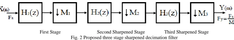
The above discussed sharpening technique is efficiently applied in multistage configuration to improve the response of proposed filter over existing structures. The proposed structure is implemented in three stages as shown in Fig. 2.
First Stage Second Sharpened Stage Third Sharpened Stage Fig. 2 Proposed three stage sharpened decimation filter
As the proposed sharpened filter is implemented in three stages, the total decimation factor M can be represented as
𝑀 = 𝑀1∗ 𝑀2∗ 𝑀3. Therefore the transfer function of proposed filter can be written as 1
𝑀 1 − 𝑍−𝑀
1 − 𝑍−1 2
1 𝑀
1 − 𝑍−𝑀
1 − 𝑍−1 2
1 𝑀
1 − 𝑍−𝑀
1 − 𝑍−1 2
𝑍− 𝑁−1
ISSN(Online): 2320-9801 ISSN (Print): 2320-9798
I
nternational
J
ournal of
I
nnovative
R
esearch in
C
omputer
and
C
ommunication
E
ngineering
(An ISO 3297: 2007 Certified Organization)
Vol. 3, Issue 5, May 2015
𝐻 𝑧 = 𝐻1 𝑍 𝐻2 𝑍𝑀1 𝐻3(𝑍𝑀1𝑀2)eq.(13)
Here 𝐻2(Z), 𝐻2(Z) and 𝐻3(Z) are transfer functions of first, second and third stage respectively.
𝐻1 𝑍 = 1 𝑀1
1−𝑍−𝑀 1
1−𝑍−1 eq.(14)
𝐻2 𝑍𝑀1 = 1
𝑀2
1−𝑍−𝑀 1𝑀 2
1−𝑍−𝑀 1 eq.(15)
𝐻3 𝑍𝑀1𝑀2 = 1 𝑀3
1−𝑍−𝑀
1−𝑍−𝑀 1𝑀 2 eq.(16)
The corresponding magnitude responses of three stages are given below
𝐻1 𝑒𝑗𝜔 = 1
𝑀1 sin 𝜔 𝑀 12
sin 𝜔 2
eq.(17)
𝐻2 𝑒𝑗𝜔 𝑀1 = 1 𝑀2
sin 𝜔 𝑀 1𝑀 2 2
sin 𝜔 𝑀 12 eq.(18)
𝐻3 𝑒𝑗𝜔 𝑀1𝑀2 = 1 𝑀3
sin 𝜔𝑀 2
sin 𝜔 𝑀 1𝑀 22 eq.(19)
The generalized transfer function of proposed three stage decimation filter is given below
𝐻𝑃𝑆 𝑍 = 𝐻1(Z) 𝐿 3 𝐻2(𝑍𝑀1) 2𝐾− 2 𝐻2(𝑍𝑀1) 3𝐾 3 𝐻3(𝑍𝑀1𝑀2) 2𝐾− 2 𝐻3(𝑍𝑀1𝑀2) 3𝐾 eq.(20)
Here, L represents the number of sub-stages in first stage and K represents the number of sub-stages in sharpened second & third stage respectively. 𝐻1(Z) , 𝐻2(𝑍𝑀1) and 𝐻3(𝑍𝑀1𝑀2) are given by eq. (14), eq. (15) and eq. (16) respectively. The
complete structure can be implemented from eq. (20). The implementation of second and third sharpened stage is shown in
Fig. 1. In proposed sharpened structure, the first stage is with decimation factor M1 can be realized in conventional recursive
or non-recursive scheme. Thus the second sharpened stage operates at lower sampling rate which is M1 times lower than the
input sampling rate. Further the third stage operates at M2 times the lower sampling rate than the second stage and the
frequency response of second stage is further sharpened by third stage.
V. SIMULATION RESULTS
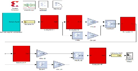
The Proposed sharpeneddecimation filter is realized and simulated in MATLAB-Simulink environment. The three stage implementation of proposed sharpened decimation filter in Matlab-Simulink is shown in Fig.3.
ISSN(Online): 2320-9801 ISSN (Print): 2320-9798
I
nternational
J
ournal of
I
nnovative
R
esearch in
C
omputer
and
C
ommunication
E
ngineering
(An ISO 3297: 2007 Certified Organization)
Vol. 3, Issue 5, May 2015
The proposed sharpened decimation filter is designed to decimate the input sampling rate by 16 (M=16). For comparison with existing results, the value of K =2 and L=4 is chosen. The decimation factor M=16 can be realized
with different possible combinations of𝑀1 𝑀2𝑀3. The proposed filter is simulated for three different combinations
of𝑀1 𝑀2𝑀3. Simulation results for 𝑀1= 4 𝑀2= 2 𝑀3= 2, 𝑀1= 2 𝑀2= 4 𝑀3= 2 𝑎𝑛𝑑 𝑀1= 2 𝑀2= 2 𝑀3= 4
are shown respectively.
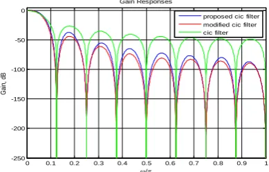
Fig. 4 Magnitude response for M=16,𝑀1= 4, 𝑀2 = 2, 𝑀3 = 2, K = 2 and L= 4 (Case I)
Fig. 4 shows the response of proposed sharpened filter for𝑀1= 4 𝑀2= 2 𝑀3= 2 (Case-I) and its comparison with
existing conventional CIC filter [2] and modified sharpened CIC filter [11]. In this case, the proposed sharpened decimation filter has shown a little improvement in pass-band droop and stop-band alias rejection as compared to existing conventional CIC filter [2] and modified sharpened CIC filter [11]. For more rigorous analysis of the results, the pass-band as well as stop-band of Fig. 4 are zoomed and shown in Fig. 5 & Fig. 6 respectively.
Fig. 5 Pass-band zoom of Case-I Fig. 6 Stop-band zoom of Case-I
Fig. 7 shows the response of proposed sharpened filter for𝑀1= 2 𝑀2= 4 𝑀3= 2 (Case-II) and its comparison
with existing conventional CIC filter [2] and modified sharpened CIC filter [11].
Fig. 7 Magnitude response for M=16 ,𝑀1= 2 , 𝑀2 = 4, 𝑀3 = 2 , K = 2 and L= 4 (Case II)
0 0.1 0.2 0.3 0.4 0.5 0.6 0.7 0.8 0.9 1
-250 -200 -150 -100 -50 0
/
Ga
in,
dB
Gain Responses
proposed cic filter modified cic filter cic filter
0 1 2 3 4 5 6 7
x 10-3 -0.1
-0.08 -0.06 -0.04 -0.02 0
/
G
a
in
,
d
B
Gain Responses: passband details
proposed cic filter modified cic filter cic filter
0.12 0.121 0.122 0.123 0.124 0.125 0.126 0.127 0.128 0.129 0.13
-250 -200 -150 -100 -50 0
/
G
a
in
,
d
B
Gain Responses
proposed cic filter modified cic filter cic filter
0 0.1 0.2 0.3 0.4 0.5 0.6 0.7 0.8 0.9 1 -250
-200 -150 -100 -50 0
/
G
ai
n,
d
B
Gain Responses
ISSN(Online): 2320-9801 ISSN (Print): 2320-9798
I
nternational
J
ournal of
I
nnovative
R
esearch in
C
omputer
and
C
ommunication
E
ngineering
(An ISO 3297: 2007 Certified Organization)
Vol. 3, Issue 5, May 2015
In this case, the proposed sharpened decimation filter has shown much improvement in pass-band droop and a little improvement in stop-band alias rejection as compared to existing conventional CIC filter [2] and modified sharpened CIC filter [11]. For more rigorous analysis of the results, the pass-band as well as stop-band of Fig. 7 are zoomed and shown in Fig. 8 & Fig. 9 respectively.
Fig. 8 Pass-bandzoom of Case-II Fig. 9 Stop-band zoom of Case-II
Fig. 10 Magnitude response for M=16,𝑀1= 2, 𝑀2 = 2, 𝑀3 = 4, K = 2 and L= 4 (Case III)
Fig. 10 shows the response of proposed sharpened filter for𝑀1= 2 𝑀2= 2 𝑀3= 4 (Case-III) and its comparison
with existing conventional CIC filter [2] and modified sharpened CIC filter [11]. In this case, the proposed sharpened decimation filter has shown a much better improvement in pass-band droop and a little improvement in stop-band alias rejection as compared to existing conventional CIC filter [2] and modified sharpened CIC filter [11]. For more rigorous analysis of the results, the pass-band as well as stop-band of Fig. 10 are zoomed and shown in Fig. 11 & Fig. 12 respectively.
Fig. 11Pass-bandzoom of Case-II Fig. 12 Stop-band zoom of Case-II
0 1 2 3 4 5 6 7
x 10-3 -0.1
-0.08 -0.06 -0.04 -0.02 0
/
G
a
in
,
d
B
Gain Responses: passband details
proposed cic filter modified cic filter cic filter
0.12 0.121 0.122 0.123 0.124 0.125 0.126 0.127 0.128 0.129 0.13 -250
-200 -150 -100 -50 0
/
G
a
in
,
d
B
Gain Responses
proposed cic filter modified cic filter cic filter
0 0.1 0.2 0.3 0.4 0.5 0.6 0.7 0.8 0.9 1 -250
-200 -150 -100 -50 0
/
G
a
in
,
d
B
Gain Responses
proposed cic filter modified cic filter cic filter
0 1 2 3 4 5 6 7
x 10-3 -0.1
-0.08 -0.06 -0.04 -0.02 0
/
G
a
in
,
d
B
Gain Responses: passband details
proposed cic filter modified cic filter cic filter
0.12 0.121 0.122 0.123 0.124 0.125 0.126 0.127 0.128 0.129 0.13 -250
-200 -150 -100 -50 0
/
G
a
in
,
d
B
Gain Responses
ISSN(Online): 2320-9801 ISSN (Print): 2320-9798
I
nternational
J
ournal of
I
nnovative
R
esearch in
C
omputer
and
C
ommunication
E
ngineering
(An ISO 3297: 2007 Certified Organization)
Vol. 3, Issue 5, May 2015
In all the three cases, proposed sharpened decimation filter shown improvement in pass-band droop and stop-band alias rejection
as compared to existing conventional CIC filter [2] and modified sharpened CIC filter [11]. But the third case with values 𝑀1=
2 𝑀2= 2 𝑀3= 4 produced best results among all proposed cases and existingstructures. Therefore from the above discussed
results, it can be concluded that the stage operating at higher sampling rate must have lowest possible decimation ratio to achieve the better frequency response.
VI.CONCLUSION AND FUTURE SCOPE
The proposed sharpened three stage CIC filter is designed and simulated in MATLAB-Simulink environment. The proposed sharpened filter produced much better improvement in pass-band droop and better alias rejection in stop-band than the existing conventional CIC filter [2] and modified sharpened CIC filter [11] for the same decimation factor. The simulation results also verify the design of proposed sharpened decimation filter. Therefore this proposed filter design is best suited for DSP based applications where the best pass-band performance is required. Thus the proposed work can be extended to design decimation filters of any decimation factor and order that can be efficiently applied to many modern multirate applications like digital modems, sampling rate equalization in GSM, 3G, 4G, WiMax and other modern communication systems.
REFERENCES
1. Mitra, S. K., “Digital Signal Processing-A Computer Based Approach”, Second Edition, McGraw-Hill, 2001.
2. Hogenauer, E. B., “An economical class of digital filters for decimation and interpolation”, IEEE Transactions on Acoustics, Speech and Signal Processing, Vol. 29, No. 2, pp. 155–162, 1981.
3. Aboushady, H., Dumonteix, Y., Louerat., M. M., and Mehrez, H., “Efficient polyphase decomposition of comb decimation filters in Sigma-Delta analog-to-digital converters”, IEEE Transactions on Circuits and Systems II: Analog and Digital Signal Processing, Vol. 48, No. 10, pp. 898 – 903, 2001.
4. Presti, L. L., “Efficient modified-sinc filters for sigma-delta A/D converters”,IEEE Transactions on Circuits and Systems II: Analog and Digital Signal Processing, Vol. 47, No. 11, pp. 1204–1213, 2000.
5. Kwentus, A. Y., Jiang, Z., and Willson, A. N., “Application of filter sharpening to cascaded integrator-comb decimation filters”, IEEE Transaction on Signal Processing, Vol. 45, No. 2, pp. 457–467, 1997.
6. Daneshgaran, F., and Laddomada, M., “A novel class of decimation filtersfor ∆A/D converters”, Wireless Communications and Mobile Computing,Vol. 2, No. 8, pp. 867–882, 2002.
7. Dolecek, G. J., and Mitra, S, K., “Sharpened comb decimator with improved magnitude response”, IEEE Transactions on Acoustics, Speech and Signal Processing, Vol. 2, pp. 929-932, 2004.
8. Dolecek, G. J., and Harris, F.,“On Design of Two-Stage CIC Compensation Filter”, IEEE International Symposium on Industrial Electronics (ISlE 2009) Seoul Olympic Parktel, Seoul, Korea, pp. 903-908, 2009.
9. Fernandez-Vazquez, A., and Dolecek, G. J.,“Maximally Flat CIC Compensation Filter: Design and Multiplierless Implementation”, IEEE Transactions on Circuits and Systems-II; Express briefs, Vol.59, No.2, pp.113-117, 2012.
10. Dolecek, G. J., and Mitra, S.K., "A New Two-Stage CIC-Based Decimation Filter",Proceedings of the 5th International Symposium on image and Signal Processing and Analysis, 2007.
11. Dolecek, G. J., and Mitra, S. K.,“A New Two-Stage Sharpened Comb Decimator”, IEEE Transaction on Circuits and Systems, Vol. 52, pp. 1414-1420, 2005.
12. Kaiser, J. F., and Hamming, R. W., “Sharpening the response of a symmetric nonrecursive filters,” IEEE Transactions on Acoustics, Speech and Signal Processing, Vol. 25, No. 3, pp. 415–422, 1977.
BIOGRAPHY
Sukhpreet Singh is a M. Tech. student in the Electronics and Communication Department of Baba Banda Singh
Bahadur Engineering College, Fatehgarh Sahib, Punjab, India. He received his Bachelor’s degree in Electronics and Communication Engg.from Punjab Technical University, Jalandhar, Punjab, India in the year 2012.He has 3 years of teaching experience as Assistant Professor. His areas of interestare Digital Signal processing, Digital communication and wireless communication.
Tripatjot Singh Panag is Assistant Professor in Electronics and Communication Department of Baba Banda Singh