R E S E A R C H
Open Access
Co-channel interference suppression for
multi-cell MIMO heterogeneous network
Yu Li
1and Zufan Zhang
1,2*Abstract
The heterogeneous network, contains a macro cell and a grid of low power nodes with the same frequencies, can improve the system capacity and spectrum efficiency. Configuring low-power nodes that share the same spectrum with macro cell to form heterogeneous networks makes it more likely to improve the system capacity and spectrum efficiency, but inevitably, strong co-channel interference is the main barrier to further improvement for heterogeneous networks. This paper proposes an algorithm which combines the triangular decomposition and signal to leakage and noise ratio (SLNR) (TD-SLNR) to suppress strong co-channel interference in multi-cell multiple input and multiple output (MIMO) heterogeneous networks. Firstly, the proposed algorithm can reduce the number of inter-cell interferences in half. As a result of triangular decomposition, an equivalent interference channel model is extracted to eliminate the rest of interferences using SLNR and interference suppression matrix. Theoretical analysis shows that the proposed algorithm provides a potential solution to suppress the co-channel interference with low complexity and reduce the computation complexity without adding extra interference suppression matrices and computation complexity at receivers. Furthermore, the simulation results show that TD-SLNR algorithm can improve system capacity and energy efficiency comparing with the traditional SLNR algorithm.
Keywords:Multi-cell MIMO heterogeneous network, Co-channel interference, Signal leakage noise ratio, Triangular decomposition
1 Introduction
In the new generation of broadband mobile communica-tion systems, multiple input and multiple output (MIMO)
technique [1, 2] and heterogeneous networks [3–5] are
key methods to enable the fast and reliable wireless communication access. On one hand, MIMO provides increased channel capacity and data rate using multiple antennas on both base stations and terminals. On the other hand, heterogeneous networks use hybrid networks with lower power nodes (pico, femto cells) and main nodes (macro cells) to achieve high-frequency efficiency and system capacity. The topology of a typical heteroge-neous network consists of one macro cell and several pico/femto cells sharing the same frequency within the one area. Such networks bring co-channel interferences (CCI) which need to be eliminated in wireless communi-cations [6–8]. For instance, users of the pico/femto cells
are affected by the strong power signal from the macro cell, whereas high power terminals at the edge of macro and pico/femto cells produce strong interferences to the surrounding pico/femto cells. It is worthwhile to investigate methods to reduce or eliminate the CCI especially after MIMO be introduced to the heterogeneous networks.
At present, interference coordination is the key tech-nology of interference suppression for heterogeneous network. The inter-cell interference in traditional networks can be significantly reduced by adjusting the spectrum
allocation and transmission power among cells [9–11].
The inter-cell interference coordination requires a cen-tral control node to achieve parameter sending and so on. However, in heterogeneous network, a large of low power nodes are randomly allocated according to the demands of users; thus, the low power nodes cannot use the X2 interface [12], which will cause strong uplink and downlink interference to adjacent cells, such as the downlink dead zone and uplink blocking [8, 13]. Therefore, the novel interference coordination schemes * Correspondence:[email protected]
1School of Communications and Information Engineering, Chongqing
University of Posts and Telecommunications, Chongqing 400065, China
2Chongqing Key Laboratory of Mobile Communication, Chongqing
University of Posts and Telecommunication, Chongqing 400065, China
designed for heterogeneous network are proposed [14–16]. For example, in [10], a self-adaptive and flex-ible algorithm about spectrum utilization is proposed; this algorithm uses flexible spectrum utilization algo-rithm in cells formed by low power nodes while adopts fixed multiplexing schemes to manage interference in the macro cell. Meanwhile, there are many studies about interference suppression using various power control schemes for heterogeneous network [17, 18]. However, the interference coordination scheme based on the spectrum allocation cannot fully exploit the spectrum, and the interference coordination scheme based on the power control will result in higher com-putation complexity and a large number of signaling interactions. Furthermore, the application of interference coordination in actual deployment is usually restrained by many factors such as implementation complexity, central management, and distribution control; thus, we will focus on using the inter-cell interference elimination to suppress the interference in the heterogeneous network.
Currently, the interference elimination mainly includes two aspects, namely pre-coding design at transmitting end and the signal detection at receiving end, respect-ively. As for signal detection, it is usually limited by the achievement of channel state information, and it has high-complexity iterative detection process [19, 20]. As for the pre-coding design, CCI suppression can employ the block diagonalization pre-coding algorithm [21–24]. However, initially, this algorithm requires the number of transmitting antennas should be greater than the total number of all users’receiving antennas, which is difficult to satisfy. At present, some regularized versions of BD-type algorithms can deal with the limitation of the num-ber of transmitting antennas [25, 26], but they are not referred to the application in multi-cell environment. Furthermore, BD algorithm will not take the problems of noise amplification into consideration; thus, it is un-realistic to put it into practice. Therefore, the signal to leakage and noise ratio (SLNR) algorithm proposed by Sadek is chosen to be the criterion of pre-coding design [27]. This algorithm maximizes the ratio of signal over the sum of leakage and noise, decomposes the multi-user MIMO system into multiple collateral and independent single-user MIMO systems, so that it is not restricted by the number of antennas, and gets the pre-coding matrices of each user independently, so the better interference sup-pression performance and extensive application scenarios can be obtained [28–31]. Moreover, in order to reduce the inter-cell co-channel interference, the interference align-ment technology is adopted in multi-cell MIMO network [32, 33]. Generally, the interference alignment technology designs the interference suppression matrices at receivers and aligns the interference signal to the corresponding zero zones of interference suppression matrices to suppress
the inter-cell co-channel interference. Though the interfer-ence alignment technology is helpful to suppress the inter-cell and intra-cell interference as well as enhance the system capacity, it will undoubtedly increase the number of interference suppression matrices at receivers and its corresponding computation complexity.
Summarized the previous works, this paper propose an interference suppression algorithm combining triangu-lar decomposition and SLNR to solve the problems of the co-channel interference suppression for multi-cell MIMO heterogeneous network. The contributions and innova-tions of this paper are summarized as follows:
This paper firstly discusses the interference situation of the network and then proposes an interference suppression algorithm combining triangular decomposition and SLNR under the considered network. This algorithm can reduce the number of inter-cell interferences in half through using triangular decomposition to the joint channel matrix, before interference suppression process at receiver.
Based on the equivalent interference model, combining with the SLNR algorithm, this paper computes the pre-coding matrices of each user in each cell and the corresponding closed-form interference suppression matrices in detail according to the different interference situations of each cell.
Considering the computation complexity, we compare the proposed algorithm with the traditional SLNR as well as the algorithm adopting interference alignment technology.
We verify that comparing the proposed algorithm with traditional SLNR, a great improvement of system capacity and energy efficiency can be achieved. Furthermore, the impact of different number of data streams and antennas on the system performance is further analyzed.
The remainder of this paper is organized as follows. Section 2 mainly discusses the interference situations in multi-cell MIMO heterogeneous network. Section 3 makes a detailed introduction about the proposed algorithm which combines the triangular decomposition and SLNR. Further-more, the computation complexity of the proposed algo-rithm with the traditional SLNR as well as the algoalgo-rithm adopting interference alignment was compared. The simulation results will be discussed in Section 5. Finally, conclusions are presented in Section 6.
2 The interference situation discussion for multi-cell MIMO heterogeneous network
cells. Figure 1 describes a universal downlink interference model in heterogeneous network, where the macro BS represents the macro base station in the network, the MUE represents the user belonging to macro BS, the pico BS indicates the base station in pico cell, and PUS repre-sents the user belonging to pico BS. The circular region circled by dotted line is the coverage area of pico cell.
As shown in Fig. 1, there are two kinds of interfer-ences in the model, including interference from macro BS to PUS and interference from pico BS to MUS. Due to the different path loss from pico BS to MUS, the re-ceived interference strength of different MUS is not the same. It is obvious that MUS1 may receive the strongest interference, MUS2 followed but also relatively strong, and MUS3 may receive the weakest interference strength. Furthermore, as the path loss from macro BS to MUS2 and MUS3 is much more than that to MUS1 and if we want to make the received signal to interference plus noise ratio (SINR) of each user the same, it is needed to increase the transmitting power of macro BS, which will result in strong interference from macro BS to PUS.
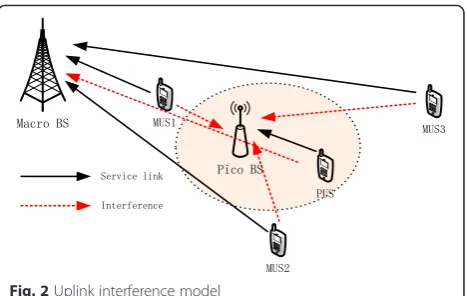
The uplink interference model in heterogeneous net-work is shown in Fig. 2. There are also two kinds of interference in the model, including interference from MUS to pico BS and interference from PUS to macro BS, respectively. According to the discussion of down-link, it may be considered that the interference from MUS1 and MUS2 to the uplink of pico BS is stronger enough: meanwhile, it is weaker to that of MUS3. How-ever, the interference situations from MUS to the uplink of pico BS are quite different. If the macro BS requires the same receiving SINR from different MUS, but due to the different path loss of MUS1 and MUS2 to macro BS, the uplink transmission power of MUS2 should be much higher than that of MUS1, thus result in the interference from MUS2 to the uplink of pico BS is much stronger than the interference from MUS1 to the uplink of pico BS. Moreover, though MUS3 is far away from pico BS, the interference from MUS3 to the uplink of pico BS is the strongest. The path loss of MUS3 to macro BS is the
largest one; so if macro BS requires the same receiving SINR from MUS3 and MUS1, the transmission power of MUS3 needs to be greatly enhanced; this results in the strongest interference from MUS3 to the uplink of pico BS. Similarly, the edge users of pico cell also need higher transmission power, which may result in interference to macro BS.
In conclusion, the interference situations in multi-cell MIMO heterogeneous network are absolutely different with that in traditional macro cell. According to the above discussion, we know that it is not suitable for the interference suppression of multi-cell MIMO heteroge-neous network through judging the interference strength and designing the corresponding interference coordination scheme just according to the users’ locations. Thus, this paper proposes an interference elimination algorithm for edge users, which can fully eliminate the interference ac-cording to the various interference situations on terminals.
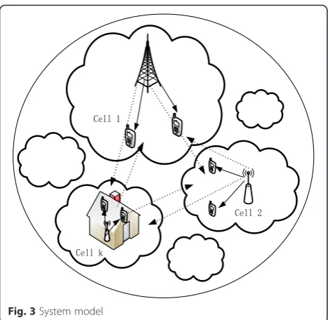
For the convenience of analysis, the interference model has only one low-power cell. In the following, the system model of a multi-cell MIMO heterogeneous network is in-vestigated, as shown in Fig. 3. Considering that there are K cells, including the low-power nodes such as macro cells and pico cells, they share the same spectrum. Thus, it is obvious that there are strong co-channel interferences exist in the system model, especially for the edge users. For the sake of convenience, it is supposed that there are only two edge users who not only receive the desired sig-nals (the solid line represents in Fig. 3) from native cell but also receive the co-channel interference signals (the dotted line represents in Fig. 3) from other K-1 cells.
3 Co-channel interference suppression
Based on the system model considered above, supposing
that the BS is equipped with Nt antennas, the user is
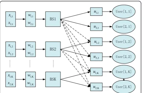
equipped withNrantennas, so constitutes a (K,Nt) × (2,Nr) MIMO interference channel model, as shown in Fig. 4. Due to the purpose of enabling the same signal space dimension that is provided by each transmitter, it can be assumed that each user has the same degrees of freedom d (Dof).
Fig. 1Downlink interference model
Thus, the received signal of ith user inkth cell can be expressed as
yi;k¼ ui;k
HHi;k
b wkxkþ ui;k
H XK
b≠k;b¼1
Hi;k
b wbxbþ ui;k
Hn
i;k
ð1Þ
where, xk= [(x1,k)T, (x2,k)T]T indicates the 2d× 1 data streams sent by the BS inkth cell;x1,k, x2,kare thed× 1 data streams sent by the BS inkth cell to users 1 and 2, re-spectively, satisfying the power constraintE xH
kxk
¼P kð Þ; Hi;k
b which represents theNr×Ntchannel matrix between
the BS in thebth cell and theith user in thekth cell;ui,kis the intra-cell interference suppression matrix of theith user in thekth cell, and (ui,k)Hui,k=Id;wk= [w1,k,w2,k] is the Nt× 2ddimension pre-coding matrix; w1,k andw2,k are
the Nt×d dimension pre-coding matrices of users 1
and 2 in the kth cell, respectively; ni,k is the Nr× 1 di-mension additive white Gaussian noise with zero-mean, unit variance, andE½ni;kðni;kÞH ¼INr:
3.1 Triangular decomposition of the equivalent channel From the point of joint channel matrix of all cells, this paper exploits triangular decomposition to the joint channel matrix. It can be seen from the discussion about the downlink interference in Section 2 that different base stations have different transmission power, which results in different degree of interference on users, and the base stations with higher transmission power have stronger co-channel interference to edge users of other cells. Thus, due to the different extent of interference on different users, it is needed to rank the receiving signal powers of users in different cells then obtain the suitable joint chan-nel matrix by adjusting the row vectors of joint chanchan-nel matrix.
Here, by computing the norms Hik;k2
F of channel
matrices between the base stations and the native users, the row vectors of joint channel matrix can be adjusted and ranked according to the values of norms. Besides, Hi;k
b can be further expressed asTH
0i;k
b R;, whereTandR are the power gains of transmitter and receiver,
respect-ively. So the Hik;k2
F norm of channel matrices between
base stations and native users can be calculated [34].
Hi;k k
2
F¼
XNt
j¼1
hj
2 2¼
XNt
j¼1
λj Hik;k
H
Hi;k k
ð2Þ
where, λj is the jth eigenvalue of Hik;k
H
Hik;k matrix
whose rank is Nt. It is observed that the Hik;k2 F norm reflects the magnitude of the desired signal power of the
ith user in the cell and the situation of transmission
power of native base stations as well. Therefore, the row vectors of joint channel matrix can be adjusted and
ranked according to Hik;k2
F: assuming that the H
i;k k
2
F norms of the channel matrix of K cells are ranked as follows:
Hi;a a
2
F≥ H
i;b b
2
F≥⋯≥ H
i;K K
2
F ð3Þ
According to the ranking result, corresponding cells are named as cell 1, cell 2,…, cellK.
In the following, the triangular decomposition of the equivalent channel will be discussed. The received signal
Fig. 3System model
of the ith user in the kth cell without interference sup-pression operation can be expressed as
yi;k¼Hi
According to the above comparison result of channel
norms, the joint received signals Yof the whole system
can be written as [35]
Y¼
to merge the channel
matri-ces,Hbjis the joint channel matrix between two users in the jth cell and the base station in the bth cell; its
di-5 is the joint
chan-nel matrix of the whole system and its dimensions is 2KNr× KNt.
Then the joint channel matrixHis adjusted by the fol-lowing triangular decomposition
H¼
is the 2Nr×Nt dimension matrix,
and the dimension of R1b;jandRb2;j isNr×Nt, whereRis the lower triangular matrix and its dimension is 2KNr×
KNt,where U is unitary matrix and its dimension is
KNt× KNt. Thus, (6) can be equal to
Thus, equation (8) can be rewritten as
Y¼
As can be known from (10), the received signals with-out the complex interference suppression processing can be equivalent to
y1¼
channel matrix. R1b;j and R2b;j, whose dimension isNr×
Nt, represents the equivalent channel matrices between
base stations ofbth cell and user 1, user 2 in thejth cell, respectively. V1,k and V2,k represent the equivalent pre-coding matrices of user 1 and user 2 in thekth cell, and the dimension is Nt×d, Vk= [V1,k,V2,k], is Nt× 2d di-mension matrix,k= 1,2,…,K.
Through the above analysis, the interference channel model described in Fig. 4 can be equivalent to that in Fig. 5. As can be known from (11), after using the triangular decomposition for joint channel matrix, the users of cell 1 in equivalent model do not receive the interference from other cells (inter-cell interference) but only receive the intra-cell interference. As can be known from (12), the users of cell 2 only receive the interference from cell 1 and intra-cell interference. As can be known from (13), the users in the kth cell receive the interference from cells 1, 2,…, k-1 and the intra-cell interference. Therefore, the number of inter-cell interferences in half is reduced through using triangular decomposition for joint channel matrix, without other complex interference suppressing operation, which reduces the computation complexity at receiver.
In the following, considering to employ SLNR to de-sign the pre-coding matrixVi,kwith the goal of eliminat-ing the rest of inter-cell interference is to consider the meaning of the equivalent interference channel model in another way of thinking. Combined with (11), (12), and (13), it can be found that part of power that originally should be sent to native users in cell 1 was leaked to the users in cells 2, 3,…,K; thus, the SLNR is used to design pre-coding matrix Vi,1 to eliminate the interferences in each of the cells caused by cell 1, then the interference suppression matrixui,1is used to eliminate the intra-cell interference of cell 1. Similarly, the base station in kth cell leaks part of power which originally should be sent to native users to the users of cellk+ 1,k+ 2,…,K; thus,
the SLNR is used to design pre-coding matrix Vi,k to
eliminate the interferences in each of the cells caused by cell kthen also use interference suppression matrix ui,k to eliminate intra-cell interference of cellk. Meanwhile, as shown in equivalent model, the base stations in cellK do not leak power to users in other cells: thus, the equivalent pre-coding matrixVi,Kcan be used to suppress the intra-cell interference of cellK, so that the receiver in cell K does not need to increase intra-cell interference suppression matrix. It can be seen that the ultimate inter-ference channel model can be simplified as Fig. 6 after using triangular decomposition and SLNR.
In conclusion, the algorithm reduce the number of inter-cell interferences in half using triangular decompos-ition, then the rest of interference is eliminated by using SLNR to design pre-coding matrix, so that the receiver does not need to design individual interference suppression matrix to eliminate inter-cell interference, which reduces the number of interference suppression matrices and sim-plifies the computation complexity at receiver. Besides, as can be known from (9) and matrix theory that dimension matching matrices satisfy span(wkxk) = span(Vkxk), that is to say, they can be spanned to the same space, which indi-cates that the triangular decomposition will not impact the degree of freedom, so the obtaining for equivalent model will not change the degree of freedom either. There is a need to explain that the proposed algorithm is imple-mented at base stations; meanwhile, it is assumed that all stations in this system can get channel matrix information through central control or circular polling mechanism, etc.
3.2 Interference suppressing algorithm combining triangular decomposition and SLNR
According to the above analysis, it can be found that the number of inter-cell interferences in half can be eliminated by employing triangular decomposition. In order to further
decrease the number of the matrices at the receivers and the corresponding computation complexity, simplify the re-ceivers processing; SLNR algorithm is employed to further suppress the inter-cell interferences. Next, for the conveni-ence of analysis, we will take three cells as example to analyze the process of suppressing the interference for each cell in detail.
3.2.1 Interference suppression of cell 1
The users of cell 1 utilize the interference suppression matrixui,1to eliminate the intra-cell interference [35]. The received signal of the users in cell1 can be expressed as
r1¼ rr1;1
Furthermore, the signal received by theith user can be expressed as
The user 1 needs to align the interference signal to the corresponding null space of the interference suppression matrixu1,1; thus, it should satisfy the following constraint:
u1;1
Therefore,u1,1is the eigenvector corresponding to the minimum eigenvalue
Similarly, the interference suppression matrix of the user 2 in cell 1 should satisfy the following constraints:
u2;1
Therefore, the interference suppression matrix is
u2;1¼vdmin R
Considering formulas (11), (12), and (13), the users in cell 2 and cell 3 will receive the inter-cell interference from cell 1, combining the SLNR algorithm [36], that is to say, the user 1 in cell 1 not only leaks part of power to user 2 in cell 1 but also part of power to the users in
cell 2 and cell 3. So the signal to leakage and noise ratio of use 1 in cell 1 is
Since the power of transmitting data is normalized and (ui,k)Hui,k=Ik,, thus
Under the certain power constraint, the standard of SLNR algorithm that determines the pre-coding vector is to maximize the SLNR, which is to find the equivalent
pre-coding matrix V1,1 satisfying the following two
equations:
Rewritten the (21) as
SLNR¼ R
According to the conclusions of generalized Rayleigh quotient, the pre-coding vectors are mutually
or-thogonal, the V1,1 is the eigenvectors corresponding
to the d largest generalized eigenvalues of the matrix
R1;1
; which enable
maximize the SLNR, that is
V1;1∝max:eigenvector R11;1
Similarly, the pre-coding matrixV2,1 of the user 2 in cell 1 should satisfy
V2;1∝max:eigenvector R21;1
3.2.2 Interference suppression of cell 2
r2¼ rr1;2
The acquisition of the intra-cell interference suppres-sion matrix of the users in cell 2 is similar to that of users in cell 1; the constraints can be expressed as
u1;2
Thus, interference suppression matrix can be expressed as
u1;2¼vdmin R
Similarly, it can be seen from formula (13) that the user 1 in cell 2 leaks the part of power to the user 2 in cell 2 as well as the users in cell 3. Combined with the SLNR algorithm, the signal to leakage and noise ratio can be expressed as
SLNR¼
∥
ðu1;2ÞNormalizing the power of transmitting data, and since (ui,k)Hui,k=Ik, thus
The confirmation for the equivalent pre-coding matrix
V1,2 obtained from SLNR algorithm should satisfy the
following two formulas
V1;2¼ arg max SLNR
Rewritten the (32) as
SLNR¼ R
V1,2is the eigenvectors corresponding to the d
largest generalized eigenvalues of the matrix
R1;2
to maximize the SLNR, namely
V1;2∝max:eigenvector R12;2
In a similar way, the pre-coding matrixV2,2of the user 2 in cell 2 should satisfy
V2;2∝max:eigenvector R22;2
3.2.3 Interference suppression of cell 3
The received signal of the users in cell 3 can be expressed as
As can be seen from formulas (11), (12), and (13), after triangular decomposition, the power that is sent by the BS in cell 3 does not leak to other cells, namely, result in no interferences to other cells. Therefore, the pre-coding matrices of each user in cell 3 are used to eliminate the intra-cell interferences, so the pre-coding matrix should satisfy the following constraints
R1;3
Moreover, the pre-coding matrix of the users 1, 2 in cell 3 can be expressed as
V1;3¼vdmin R
4 Algorithm complexity analysis 4.1 Summarize the algorithm
The proposed algorithm that combines the triangular decomposition and SLNR can be implemented by three steps:
Step1. Employ the triangular decomposition for joint
channel matrix H and then extract the equivalent
inter-ference channel model;
Step2. According to the equivalent interference channel model, exploit SLNR to compute the equivalent pre-coding matricesV1,1,V2,1,V1,2, andV2,2to suppress the rest of in-ter-cell interference and then obtain w1,1, w2,1, w1,2 and w2,2;
Step3. Compute the intra-cell interference suppression matrices of users u1,1, u2,1, u1,2 and u2,2, respectively. Specially, the users in cell 3 use the equivalent pre-coding matricesV1,3 and V2,3 to eliminate the intra-cell interference, so the receiver does not need to add intra-cell interference suppression matrix any more.
4.2 Complexity analysis
Furthermore, the complexity of the triangular decom-position and SLNR algorithm is analyzed.
AandBare matrices whose dimensions arem×n,n×k, respectively; the complexity of operationA×Bis ο(mnk).
Thus, the complexity of operation Hi;k
b H
Hi;k
b is ο(Nt
2 Nr), where,Hi;k
b is the channel matrix whose dimension isNr×Nt,
and the complexity of eigenvalues operation for Nt×Nt
dimension matrixCisο(Nt3). Therefore, the complexity of the algorithm that combines the triangular decomposition and SLNR can be concluded as follows:
Step1. Employ the triangular decomposition forH, the according complexity isο 262N2
rð3Nt−6Nr=3Þ
;namely,
ο 3N2rNt−2N3r
;
Step2. Exploit SLNR algorithm to calculate the equiva-lent pre-coding matricesV1,1,V2,1,V1,2, and V2,2to sup-press the rest of inter-cell interference, the according complexity iso N3
t þo N2tNr
;
Step3. Compute the intra-cell interference suppression matrices of usersu1,1, u2,1, u1,2 and u2,2, respectively. Specially, the users in cell 3 use the equivalent
pre-coding matrices V1,3 and V2,3 to eliminate the
intra-cell interference; the total complexity is o N3
r þ o N3t þo dN2r
þo N2tNr
þo dNð rNtÞ:
Therefore, according to above analysis, the total
com-plexity of the proposed algorithm is o N3
r þo N3t þ o N2rNt
þo N2tNr
þo dN2r
þo dNð rNtÞ:
However, exploit the interference alignment algorithm to suppress the rest of inter-cell interference, corre-sponding complexity is ο N2rNt
þο N3r þο d3NrN2t
þο d3N3
t
[35]. Meanwhile, the complexity of the trad-itional SLNR without using triangular decomposition
to the multi-cell MIMO interference system iso N3r þo N3t þo dN2r
þo dNð rNtÞ þo N2tNr
: It obviously
seen that under the condition with certain configuration of antennas, the complexity of the proposed algorithm and the traditional SLNR are on the same order of magnitude, which means that the proposed algorithm without increas-ing complexity to the system compared with traditional SLNR algorithm. Furthermore, comparing with employing the interference alignment algorithm to compute the inter-cell interference suppression matrix at receiver [35], the proposed algorithm reduces the number of filters (matrices) at receiver, which is helpful to avoid more complex interfer-ence suppression process and have lower computation complexity as well as reduce costs of receiver.
5 Numerical results
In the downlink communication environment with co-channel interference of multi-cell MIMO heterogeneous network, the performance of the whole system will be af-fected by the antenna configurations both of transmitter and receiver; it will also be affected by the data streams sent by the transmitter. At present, the system capacity is usually used as one of the reference indexes to evaluate the system performance, and the energy consumption is a noteworthy problem as well. Thus, the system capacity and energy efficiency are chosen to be the indexes to evaluate the system performance. The system capacity is defined asC= log(1 + SINRk) (bps/Hz), and the energy ef-ficiency is defined as the number of bits sent by in unit of energy and unit of bandwidth, namely, η¼ log 1ðþSINRkÞ
Pk (bit/Hz/J), SINRkrepresents the signal to interference plus noise ratio ofkth user andPkrepresents the transmission
power of kth user. Aiming at network environment is
formed by three cells sharing the same frequency resource, in which each cell has two edge users. Assuming that all channels are flat Rayleigh fading channels with the ele-ments that are independent identically distributed Gauss-ian random variables whose mean is 0, varGauss-iance is 1.
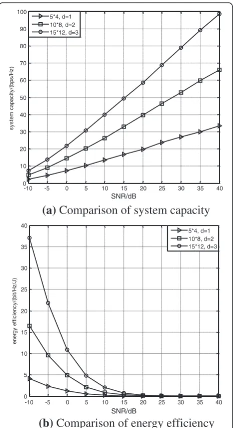
Figure 7a, b shows the comparing results of system capacity and energy efficiency when the antenna config-urations are 5 × 4, 10 × 8, and 15 × 12, respectively, and the numbers of received data streams (the degree of freedom) of each user are d= 1, 2, 3, the degree of sys-tem freedom are Dof = 6, 12, 18. As can be seen from Fig. 7, the system capacity and energy efficiency are obviously promoted with the increase of numbers of antenna as well as data streams. The reason for this phenomenon is the system obtains more diversity gains and the transmitter sends multiple collateral data streams simultaneously, which is very helpful to improve the system performance.
environment butd= 1, Dof = 6, and the antenna config-urations are different. As can be known from Fig. 8, in-creasing the number of transmitting and receiving antenna can improve the system capacity and energy ef-ficiency under the fixed Dof, especially the improvement of energy efficiency is more obvious. However, the fur-ther improvement of system performance is relatively slow with the increase of number of antenna. Thus, the antenna should be reasonably allocated according to the actual situation.
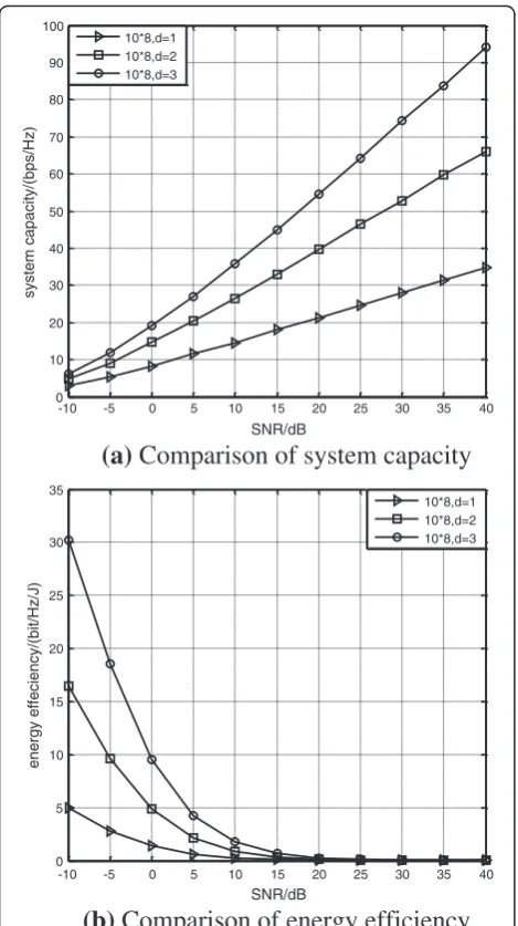
Figure 9a, b shows the comparing results of system capacity and energy efficiency with the same antenna configuration 10 × 8 and simulation environment, but different number of received data streams (the degree of
freedom)d= 1,2,3, Dof = 6,12,18. As can be known from
Fig. 9, the increasing of number of transmission data streams can improve the system capacity and energy effi-ciency obviously with fixed antenna configuration, and the improvement of energy efficiency is more obvious than system capacity as well. Therefore, it is needed to send multiple data simultaneously to improve system performance under the reasonable condition.
In the same simulation environment, Fig. 10a, b shows the results of system capacity and energy efficiency comparing the proposed triangular decomposition SLNR algorithm with traditional SLNR. As can be seen from Fig. 10, the proposed algorithm can greatly improve the system capacity comparing with the traditional SLNR under the same numbers of antennas and data streams.
-10 -5 0 5 10 15 20 25 30 35 40 0
10 20 30 40 50 60 70 80 90 100
SNR/dB
)
z
H/
s
p
b(/
yti
c
a
p
a
c
m
et
s
y
s
5*4, d=1 10*8, d=2 15*12, d=3
(a)
Comparison of system capacity
-10 -5 0 5 10 15 20 25 30 35 40 0
5 10 15 20 25 30 35 40
SNR/dB
)
J/
z
H/t
i
b(/
y
c
n
ei
cif
f
e
y
gr
e
n
e
5*4, d=1 10*8, d=2 15*12, d=3
(b)
Comparison of energy efficiency
Fig. 7System performance analysis.aComparison of system capacity.bComparison of energy efficiency
-10 -5 0 5 10 15 20 25 30 35 40 0
5 10 15 20 25 30 35
SNR/dB
system capacity/(bps/Hz)
2*2,d=1 5*4,d=1 10*8,d=1
(a)
Comparison of system capacity
-10 -5 0 5 10 15 20 25 30 35 40 0
1 2 3 4 5 6
SNR/dB
energy efficiency/(bit/(Hz.J))
2*2,d=1 5*4,d=1 10*8,d=1
(b)
Comparison of energy efficiency
Meanwhile, it can be found from Fig. 10 that though the proposed algorithm does not have significant advantages in improving energy efficiency compared with the trad-itional SLNR, the proposed algorithm still has better per-formance than that of traditional SLNR in improving energy efficiency under the same condition.
It can be figured out that the traditional SLNR algo-rithm only reduce the inter-cell interference at receiver, the strong interference may weaken the interference suppression ability of SLNR, which causes the degradation of system performance. However, the proposed algorithm can reduce the number of inter-cell interferences in half before the interference suppression operation at receiver, so the interference environment at receiver is improved,
and the application effect of the SLNR algorithm is enhanced; finally, the overall system performance is improved.
It should be noted that the analysis and studies of this paper are based on the ideal channel estimation and the actual method for obtaining channel state information is not further studied. Of course the acquisition of real-time channel state information under the actual channel condition can be studied in following. Furthermore, the performance of the proposed algorithm with real-time channel states information will be analyzed.
6 Conclusions
This paper firstly discusses the interference situations in multi-cell MIMO heterogeneous network. Aiming at the
-10 -5 0 5 10 15 20 25 30 35 40 0
10 20 30 40 50 60 70 80 90 100
SNR/dB
system capacity/(bps/Hz)
10*8,d=1 10*8,d=2 10*8,d=3
(a)
Comparison of system capacity
-10 -5 0 5 10 15 20 25 30 35 40 0
5 10 15 20 25 30 35
SNR/dB
energy effeciency/(bit/Hz/J)
10*8,d=1 10*8,d=2 10*8,d=3
(b)
Comparison of energy efficiency
Fig. 9Comparison of system performance with the same number of antennas but different number of degree of freedom.aComparison of system capacity.bComparison of energy efficiency
-10 -5 0 5 10 15 20 25 30 35 40 0
10 20 30 40 50 60 70
SNR/dB
system capacity/(bps/Hz)
Traditional SLNR 5*4,d=1
Triangular Decomposition SLNR 5*4,d=1 Traditional SLNR 10*8,d=2
Triangular Decomposition SLNR 10*8,d=2
(a)
Comparison of system capacity
-10 -5 0 5 10 15 20 25 30 35 40 0
2 4 6 8 10 12 14 16 18
SNR/dB
energy efficiency/(bit/(Hz.J))
Traditional SLNR 5*4,d=1
Triangular Decomposition SLNR 5*4,d=1 Traditional SLNR 10*8,d=2
Triangular Decomposition SLNR 10*8,d=2
(b)
Comparison of energy efficiency
Fig. 10Comparison of system performance with different algorithms.
strong co-channel interference in multi-cell MIMO heterogeneous network, an algorithm that combines the triangular decomposition and SLNR has been proposed. The algorithm can reduce the number of cell inter-ferences in half through exploiting the triangular decom-position for equivalent channel matrix before the complex interference suppressing operation at receiver. Then based on the equivalent interference channel model extracted after triangular decomposition, the pre-coding matrices of each user in each cell and the corresponding closed-form interference suppression matrices are derived according to different interference situations in each cell. Furthermore, we compare the computation complexity of the proposed algorithm with traditional SLNR and interference align-ment algorithm. Finally, the simulation results verify that the proposed algorithm can greatly improve the system capacity and energy efficiency compared with traditional SLNR algorithm. Meanwhile, the impact of different num-bers of data streams and antennas on system performance is further analyzed.
Competing interests
The authors declare that they have no competing interests.
Acknowledgements
This work was supported in part by the National High Technology Research and Development Program of China (863 Program) under Grant No. 2014AA01A705, The National Natural Science Foundation of China under Grant No. 61440062, and the Program for Changjiang Scholars and Innovative Research Team in University under Grant No. IRT1299.
Received: 13 May 2015 Accepted: 9 February 2016
References
1. M Chiani, MZ Win, S Hyundong, MIMO networks: the effects of interference. IEEE Trans. Inf. Theory56(1), 336–349 (2010)
2. XR Jing, ZZ Zhou, Z Xu, A sequence detection method with adaptive channel tracking in time-varying multipath MIMO channels. J. Electron. Inf. Technol.31(8), 1930–1934 (2009)
3. A. Khandekar, N. Bhushan, T.F. Ji, V. Vanghi. LTE-advanced: heterogeneous networks. European Wireless Conference, 978-982 (2010).
4. A. Jabban, Y. Nasser, M. Helard, Performance analysis of heterogeneous networks based on SINR selection strategy. International Conference on Telecommunications, 1-5 (2013).
5. N. Himayat, S.P. Yeh, A.Y. Panah, Multi-radio heterogeneous networks: architectures and performance. International Conference on Computing, Networking and Communications, 252-258 (2014).
6. P. Palanisamy, S. Nirmala, Downlink interference management in femtocell networks—a comprehensive study and survey. International Conference on Information Communication and Embedded Systems, 747-754 (2013). 7. K.I. Pedersen, Y.Y. Wang, B. Soret, eICIC functionality and performance for
LTE HetNet co-channel deployments. IEEE Vehicular Technology Conference, 1-5 (2012).
8. Y.J. Hong, L. Namyoon, B. Clerckx, System level performance evaluation of inter-cell interference coordination schemes for heterogeneous networks in LTE-A system. IEEE GLOBECOM Workshops, 690-694 (2010).
9. Z. Bakhti, S.S. Moghaddam, Inter-cell interference coordination with adaptive frequency-reuse for VoIP and data traffic in downlink of 3GPP-LTE. International Conference on Application of Information and Communication Technologies, 1-6 (2010).
10. C. He, F. Liu, H. Yang, Co-channel interference mitigation in MIMO-OFDM system. International Conference on Wireless Communications, Networking and Mobile Computing, 204-208 (2007).
11. A Bagayoko, I Fijalkow, P Tortelier, Power control of spectrum-sharing in fading environment with partial channel state information. IEEE Trans. Signal Process.59(5), 2244–2256 (2011)
12. 3GPP TR 36.814, Further advancements for E-UTRA physical layer aspects (Release 9), v. 2.0.0, Mar. 2010.
13. N Saquib, EE Hossain, LB Le, Interference management in OFDMA femtocell networks: issues and approaches. IEEE Wireless Commun.19(3), 86–95 (2012) 14. B. Li, An effective inter-cell interference coordination scheme for
heterogeneous network. IEEE Vehicular Technology Conference, 1-5 (2011). 15. Y. Li, M.G. Peng, W. Hu, Adaptive heterogeneous interference coordination
algorithm in uplink LTE-advanced systems. IEEE International Symposium on Personal Indoor and Mobile Radio Communications, 536-540 (2012). 16. J Mestre, N Pratas,N R Prasad, Adaptive flexible spectrum usage algorithms in
heterogeneous cell deployment IEEE International Symposium on Personal Indoor and Mobile Radio Communications, 253–257, 2011
17. Q Li, RQ Hu, YR Xu, Y Qian, Optimal fractional frequency reuse and power control in the heterogeneous wireless networks. Wireless Communications. IEEE Trans. Wireless Commun.12(6), 2658–2668 (2013)
18. R.C. Xie, H. Ji, P.B. Si, Y. Li, Dynamic channel and power allocation in cognitive radio networks supporting heterogeneous services. IEEE Global Telecommunications Conference, 1-5 (2010).
19. P Marsch, G Fettweis, Uplink CoMP under a constrained backhaul and imperfect channel knowledge. IEEE Trans. Wireless Commun.10(6), 1730–1742 (2011) 20. P Li, RC de Lamare, Distributed iterative detection with reduced message
passing for networked MIMO cellular systems. IEEE Trans. Vehicular Technol. 63(6), 2947–2954 (2014)
21. Q.H. Spencer, M. Haardt, Capacity and downlink transmission algorithms for a multi-user MIMO channel. IEEE Conference on Signal, Systems and Computers, 1384-1388 (2002).
22. P Jungyong, L Byungju, S Byonghyo, A MMSE vector precoding with block diagonalization for multiuser MIMO downlink. IEEE Trans. Commun.60(2), 569–577 (2012)
23. Y Zeng, E Gunawan, YL Guan, Modified block diagonalization precoding in multicell cooperative networks. IEEE Trans. Vehicular Technol.61(8), 3819–3824 (2012)
24. J. An, Y.A. Liu, F. Liu, An efficient block diagonalization method for multiuser MIMO downlink. International Conference on Consumer Electronics, Communications and Networks, 145-148 (2012).
25. H Sung, S Lee, I Lee, Generalized channel inversion methods for multiuser MIMO systems. IEEE Trans Commun.57(11), 3489-3499 (2009)
26. K Zu, RC de Lamare, M Haardt, Generalized design of low-complexity block diagonalization type precoding algorithms for multiuser MIMO systems. IEEE Trans. Commun.61(10), 4232–4242 (2013)
27. M Sadek, A Tarighat, AH Sayed, A leakage based precoding scheme for downlink multi-user MIMO channels. IEEE Trans. Wireless Commun.6(5), 1711–1721 (2007) 28. X.Y. Zhang, C. He, L. Jiang, Successive SLNR based precoding for
downlink multi-user MIMO systems. IEEE International Conference on Communications, 1-5 (2011).
29. P Piya, D Angela, A Simon, Equivalent expressions and performance analysis of SLNR precoding schemes: a generalisation to multi-antenna receivers. IEEE Commun. Lett.17(6), 1196–1199 (2013)
30. E. Saeid, V. Jeoti, B.B. Samir, Linear precoding for multi-cell processing multiuser MIMO systems. International Conference on Intelligent and Advanced Systems, 259-264 (2012).
31. K Wang, XD Zhang, On equivalence of SLNR-based precoding and RBD precoding. Electron. Lett.48(11), 662–663 (2012)
32. O Ayach, SW Peters, RW Heath, The practical challenges of interference alignment. IEEE Wireless Commun.20(1), 35–42 (2013)
33. G.C. Alexandropoulos, S. Papaharalabos, C.B. Papadias, On the performance of interference alignment under weak interference conditions. International Conference on Systems, Signals and Image Processing, 222-226 (2012). 34. XD Zhang,Matrix analysis and applications(Tsinghua University Press, Beijing, 2004) 35. XZ Xie, B Xu, WJ Lei, B Ma, Interference alignment algorithm based on
orthogonal-triangular decomposition for edge users in 3-cell MIMO cellular networks. J Electron. Inf. Technol.35(5), 1031–1036 (2013)