Comparison of Speed Controlling Techniques of
Field-Oriented Controlled Induction Motor Drives
M. Anka Rao 1, M.Vijaya Kumar 2, P.Mounika 3
Assistant Professor, Dept. of EEE, JNTU, Anantapur, Andhra Pradesh, India1
Professor, Dept. of EEE, JNTU, Anantapur, Andhra Pradesh, India2
PG Student [PID], Dept. of EEE, JNTU, Anantapur, Andhra Pradesh, India3
ABSTRACT
:
Various control strategies of controlling inverter fed Induction Motor Drives have proved good steadystate performance but poor dynamic performance. In order to achieve good dynamic performance and to meet the preferences set by DC drives variable speed AC Drives came into existence. This paper presents an intelligent speed controller for an indirect field oriented controlled induction motor drives. Here by separating the current produced by the stator into flux and torque producing components of an induction motor, indirect field oriented control is implemented. SVM based indirect vector controlled induction motor drive with PI controller is first developed and replaced by employing fuzzy controller via an intelligence-based Fuzzy PI controller in order to achieve better dynamic response. By considering the behaviour of the FLC the speed, torque and stator voltage responses were observed and compared with the PI controller using MATLAB/Simulink.
KEYWORDS: PI controller, FLC, indirect vector control, modelling of induction motor
I.INTRODUCTION
Today’s sophisticated industrial drives are the result of the far research and improvement during last decade. The hence so-called vector control or field oriented control (FOC) was one of the most important inventions in AC motor drives which opened the gate for the researchers to take the aim for ever enhancing control of performance. And by other aspects, there are many process control benefits that might be provided by adjustable speed drive such as smoother operation, acceleration control, different operating speeds, control of torque etc.,
In the past decades, Induction and synchronous machines were used for constant speed applications. This was mainly because of unavailability of variable frequency supply. The advancement in electric drive systems is related to the development of power semiconductor devices. The introduction of Silicon-controlled rectifier in 1957 initiated further more development in electrical drive systems. In early 1960’s, the improvement in fabrication of BJT along with the PWM technique has significantly contributed to achieve improvement in AC drives. But required precise torque control is not obtained and was still dominated by DC drives. This high performance torque control was achieved with the invention of Field Oriented Control or Vector control in 1972’, which was developed by Prof. Blashke in his publications.
The present paper involves implementation of both controllers for the IVCIM. This paper produces an improved fuzzy logic based controlling technique which is better than the conventional proportional-integral control technique and is implemented using MATLAB/Simulink. The various function blocks and equations for the modelling of FLC based speed controlling for the drive is developed in MATLAB and the results are analysed and compared.
II. PRINCIPLE OF INDIRECT FIELD ORIENTED CONTROL
Earlier scalar control techniques were used in order to control the speed which is simple to implement. But the inherent coupling effect (i.e., both the toque and flux were the function of voltage or current and frequency) gives sluggish response and due to this the system is easily prone to instability which is undesirable. This problem can be overcome by Vector control or field oriented control. This control can be applicable to induction motor and synchronous motor drives. It appears that this control will soon be accepted as the industry standard control for ac drives. Based on the estimation of field angle, vector control is of two types namely direct vector control and indirect vector control. In this work, induction motor with indirect vector control is implemented with different controlling techniques. In indirect vector control method, the unit vectors (cosθe and sinθe) are generated in feed forward manner. Field angle is estimated by sensing the rotor position. Fundamental principle of indirect vector control can be understood with the help of Fig.1
Here field angle is obtained from rotor position estimation.
θe = θr + θsl (1)
where θsl = ∫wsl dt (2)
Fig.1. Indirect vector control
With the torque and flux producing components of stator current command and rotor field angle, we get d-q axis currents. d-q axis current commands in rotating frame are then converted to stationary reference frame using transformation. In case of indirect vector control, rotor flux and torque can be independently controlled by stator axis current components ids and iqs [1,3].
A. Mathematical model of induction motor
=− − + +
=− − +
=− + + Eq. (3), (4), (5), (6)
Where = , = 1− , = , = , =
And the torque developed is
= − Eq. (7)
For indirect vector control, the torque developed is
= Eq. (8)
Any deviations in induction motor rotor flux linkages results in oscillations in Torque which leads to oscillations in speed. Space Vector pulse width modulation technique is used for the drive.
SVM method is an advanced, computation intensive technique among all the Pulse width modulation techniques that are available. In this method, it considers the interaction of phases and optimizes the harmonic content. Three phase sinusoidal and balanced voltages are applied to the induction motor drive. So, the PWM fabrication at the inverter output should be such that the average voltages should follow the command voltages resulting in minimum amount of harmonic distortion [2]. Hysteresis band PWM was also implemented in which actual current continuously tracks the command current within a hysteresis band. The output of this is fed as signals to the SVM technique and the required modulated signals are obtained. The resulted pulses are then converted according to the transformations required. SVM technique is somewhat complex and computation intensive and so the available PWM switching frequency is limited. To overcome this ANN based SVM technique can be used in further future.
III. DESIGN OF CONVENTIONAL CONTROLLERS A. PI Controller:
PI controller eliminates the forced oscillations and the steady state error that occur, resulting in reduced oscillations in the signal. Here, PI controller is used to reduce the speed error between the actual speed and reference speed i.e., speed error feeds the PI controller. The basic block diagram of PI controller is as in Fig.2
In order to tune the gain values Kp and Ki of the controller, the common technique Zeigler-Nicholas tuning method is used. In case of PI controller, if the gains exceeds certain value then the command torque variations increases and destabilizes the system. In recent years Fuzzy Logic Controller came into play and replaced PI controller.
B. Fuzzy Logic Controller:
Fuzzy controllers do not need any mathematical model for the implementation of the model plant. It is developed based on the plant operator knowledge and experience. Fuzzy control is robust and adaptive non linear control. The primary tools used for designing FLC are: FIS editor, Membership Function editor, Rule editor, Rule viewer, surface viewer. Here, the error between actual speed and reference speed is eliminated up to some extent using FLC. The basic block diagram of FLC is as in Fig 3.
Here, FLC observes the speed error signal and the corresponding output iq is updated so that the actual speed wr matches the reference command speed signal. Two input signals (error in speed and change in error) are fed to the fuzzy logic controller and the output is updated according to the input. For this, rule base is used in FLC. IF-THEN rule base is used. Here, 7×7 rule base was used according to the rules as in Table 1 i.e., 49 rules are to be developed [2,5]. The Fuzzy logic controller comprises four basic modes for its working.
Those modes are a) Fuzzification in which the crisp data of speed error is converted into linguistic variables. b) Knowledge base in which rules are formed c) Inference engine and d) Defuzzification in which the linguistic variables are again converted into crisp data of updated current iq. In simulink, FLC is designed as given in Fig 4 in which the inputs and outputs are formed with membership functions.
Rule Base:
For example, if E is PS and CE is NS then the output iq is Z. In this way rule bases are designed for the FLC according to the requirement. The Rule base for the fuzzy controller developed in this paper is as in Table2.
Table1. Rule base for controller
Therefore among the controlling techniques that available to control the speed of the induction motor drive, PI controllers are the conventional controllers and showed an overshoot in speed response and have taken more time to reach steady state. With the implementation of Fuzzy along with PI controller, the results were improved.
E NEB NEM NS Z PS PM PB
CE
NEB NVB NVB NEB NEM NS Z PS
NEM NVB NEB NEB NEM NS Z PS
NS NEB NEB NEM NS Z PS PM
Z NEB NEM NS Z PS PM PB
PS NEM NS Z PS PM PB PB
PM NS Z PS PM PB PB PVB
Fig 4. Fuzzy Logic Controller
V. PROPOSED BLOCK DIAGRAM OF IFOCIM
The proposed indirect vector control of induction motor with conventional PI controller, Fuzzy controller is modelled using the Matlab/simulink. The developed simulink model is shown in Fig.5
Fig.5. Block diagram of the proposed model
VI. RESULT AND ANALYSIS
Fig 6 (c). Stator currents
The stator d-q axis current waveforms of the motor drive are shown in Fig 6(c)
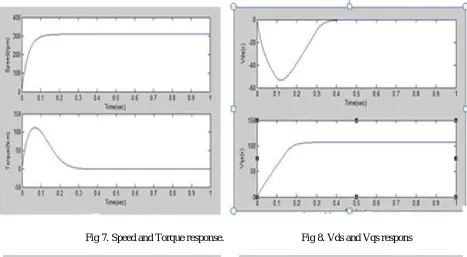
Fig 7. Speed and Torque response. Fig 8. Vds and Vqs respons
Fig 9. Stator currents Fig 10. Torque-Speed Characteristics
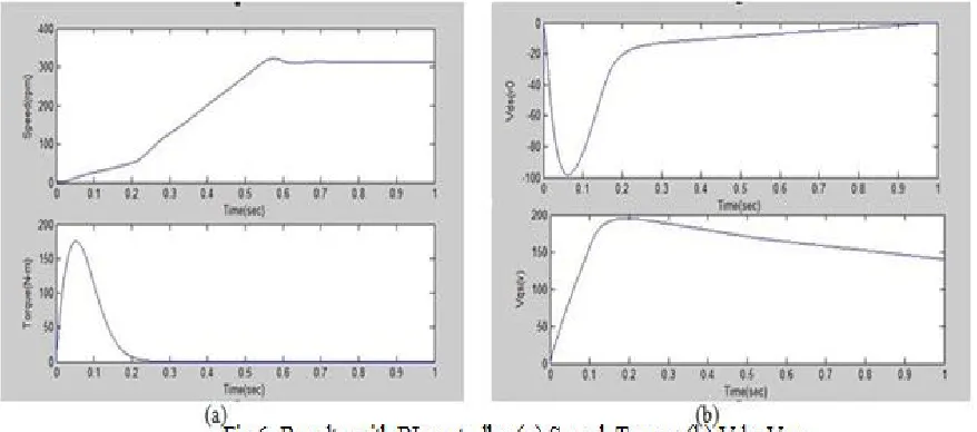
From the obtained results, it is observed that the motor started from halt at t=0 and reached rated speed of 313 rpm 0.7sec with PI controller and nearly 0.25sec with Fuzzy logic controller. The comparison of results is tabulated in Table 2.
Table 2 Summary of Results
Controller Rise Time (sec) Settling Time (sec)
PI 0.6 0.7
VII.CONCLUSION
An Artificial intelligence based approach was used in this paper to control the speed of the induction motor drive. Between the conventional PI controller and the Fuzzy Logic controller, FLC proved to be better than PI. Response with PI controller has overshoot and takes more settling time to reach rated value. But with the implementation of Fuzzy PI controller, the simulation results gave further more improved dynamic performance. This work can be investigated further by using Genetic algorithm and Neural network techniques.
APPENDIX Parameters:
Resistance of stator rs : 0.33Ω
Resistance of rotor rr : 0.17 Ω
Self-inductance of stator Ls : 0.088mH
Self-inductance of rotor Lr : 0.088mH
Magnetizing inductance LM : 0.085mH
Rotor inertia J : 0.1105kg.m2
Pole pairs : 2
REFERENCES
[1] R. Krishnan, Electric motor drives modelling, analysis and design [2] Bimal k.Bose, Modern Power Electronics and AC Drives, 2002
[3] Y.S.K.Babu, “Fuzzy Logic Speed Control of Three Phase Induction Motor Drive”, Engineering and Technology, pp. 1371-1375, 2011 [4] Ashutosh Mishra, Prashanth Choudhary, ”Speed control of an induction motor by using indirect vector control method”, IJETAE, Vol.2,
Issue 12, pp. 144-150, 2012.
[5] A. Magzoub, B. Saad, B. Ibrahim,“An intelligent speed controller for indirect field oriented control of induction motor drive”, IEEE conference 2013.
[6] D Graupe,” Principles of Artificial Neural Networks”, 2007
[7] Saghafinia, A.; Ping, H.W.; Rahman, M.A. “High performance induction motor drive using hybrid fuzzy-pi and pi controllers: A review”.
Int. Rev. Electr. Eng. IREE 2010, 5, 2000–2012.
[8] Rani S, Victore George,” Performance of ANN based Induction motor drive”, IJACTE, Vol.2, pp. 2319-2526, 2013