TRIANGULAR RESONATOR BANDPASS FILTER WITH TUNABLE OPERATION
J.-K. Xiao, Q.-X. Chu, and H.-F. Huang
School of Electronic and Information Engineering South China University of Technology
Guangzhou 510640, China
Abstract—Triangular patch resonator bandpass filters with tunable operation are developed to perform nicer filter properties of low passband insertion loss, transmission zeros and wide stopband. With tunable fractal-shaped defection acts as perturbation, filter operation frequency and operation band can be controlled, and the responses of undesired resonant modes are greatly weakened even suppressed. The new design can bring filters more operation without changing the dielectric substrate or patch size. The designed filters have outstanding advantages of single patch with compact size and without resonator coupling gaps, simple circuit topology, nicer performances, miniaturization and can be easily tuned for more applications. All these features are well popular for wireless communication systems.
1. INTRODUCTION
compared with that of square and circular ones, and most of the reported filters consist of several resonators and exist of coupling gaps, which bring larger sizes. Literature [12] gives a dual-mode bandpass filter using triangular loop resonator, however, it only operates at a single band and single frequency, and only one transmission zero is implemented.
The basic principle for designing a patch resonator filter is the selectivity and application of all sorts of resonant modes. Currently, many patch filters are designed with dual-mode (the dominant mode and its degenerate mode) operation, and the numerous higher order modes are not applied. In our design, higher order modes are utilized and filter operations are extended. For the filter first higher order mode operation, the responses of neighboring modes such as the dominant mode ought to be weakened even suppressed, and simultaneously its resonance should be as far as possible from the operating frequency in order to minimize the interference, and it’s the same for the other modes operation. The most feasible way for this implementation is a proper perturbation. In this article, patch etched defection which may be called fractal [13, 14] defection is introduced to act as the perturbation, and if it is properly controlled, operation of the unwanted modes can be weakened even suppressed, simultaneously the desired filter property can be obtained, and the most importance is that filter operation frequency and band are tunable without requiring to change the dielectric substrate and patch size. According to the above principle, new miniature bandpass filters with tunable operation by using single patch triangular resonators are designed, and all have low passband insertion losses and high selectivity. For each of our design, the patch defection size is fixed.
2. RESONANT PERFORMANCE OF EQUILATERAL TRIANGULAR RESONATOR
Microstrip triangular resonator has important applications in microwave circuits, especially the equilateral one, which has exact solving methods. For TM mode in an equilateral triangular resonator, the electromagnetic field patterns have no variation along the thickness direction, and electric field component Ez satisfies the 2-D Helmholtz
equation
∂2
∂x2 +
∂2
∂y2 +k
2
m,n,l
Ez = 0, km,n,l=
4π
3a
m2+mn+n2 (1)
components can be written as
Ez =Am,nT(x, y), Hx=
j
ωµ0µr
∂Ez
∂y ,
Hy = −
j
ωµ0µr
∂Ez
∂x , Ex =Ey =Hz = 0
(2)
The resonant frequency for the dominant mode TM1,0,−1 and higher
order modes can be expressed as
f1,0,−1=
2c
3a√εr, fm,n,l=f1,0,−1
m2+mn+n2 (3)
where, c is wave velocity in free space, εr is the relative dielectric
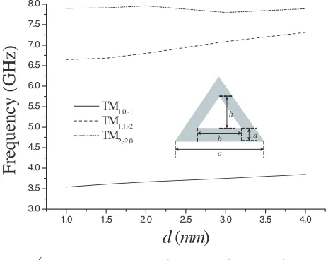
coefficient of substrate. The above resonant equations are important guidelines for filter design. It can be calculated that for an equilateral triangular resonator withεr= 9.8 anda= 15 mm, resonant frequencies
of the dominant mode TM1,0,−1 and the first higher order mode
TM1,1,−2 are 4.26 GHz and 7.38 GHz, respectively. If a perturbation
is introduced, resonant frequencies may be fluctuated. Calculated resonant performances of the equilateral triangular resonators with patch defection are shown in Fig. 1–Fig. 3, it can be seen resonant frequency of the perturbed resonator is lower than the integrated one, and resonant frequencies of the dominant mode TM1,0,−1 and
1.0 1.5 2.0 2.5 3.0 3.5 4.0 3.0
3.5 4.0 4.5 5.0 5.5 6.0 6.5 7.0 7.5 8.0
h
a
b d
Frequency
(GHz)
d
(
mm
)
TM1,0,-1
TM1,1,-2
TM2,-2,0
(εr= 9.8,a= 15 mm,b= 8 mm,h= 6 mm)
1.0 1.5 2.0 2.5 3.0 3.5 4.0 3.5
4.0 4.5 5.0 5.5 6.0 6.5 7.0 7.5 8.0
a
b d
h
Fr
equency
(
G
H
z)
d (mm)
TM
1,0,-1
TM1,1,-2 TM
2,-2,0
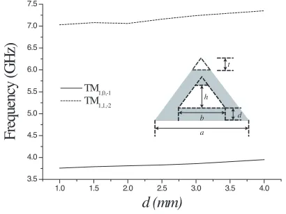
(εr= 9.8,a= 15 mm,b= 8 mm,h= 4 mm)
Figure 2. Resonant property of the equilateral triangular resonator with trapezoidal defection.
1.0 1.5 2.0 2.5 3.0 3.5 4.0 3.5
4.0 4.5 5.0 5.5 6.0 6.5 7.0 7.5
a
b d
h t
Fr
equency
(
G
H
z)
d (mm)
TM1,0,-1 TM1,1,-2
(εr= 9.8,a= 15 mm,b= 8 mm,h= 4 mm,t= 3 mm)
Figure 3. Resonant property of the equilateral triangular resonator with trapezoidal defection and top triangle cut.
the first higher order mode TM1,1,−2 increase with d increasing,
and the resonant frequency distance between TM1,0,−1 mode and
TM1,1,−2 mode are much wider than that between mode TM1,1,−2 and
the second higher order mode TM2,−2,0. Where, d is the distance
closer resonant modes can be applied for implementing a multi-mode resonator filter, and the tunable fractal structure is easy for the first higher order mode splitting which brings TM1,1,−2 degenerate mode.
On the other hand, resonances of TM1,1,−2 degenerate mode and
TM2,−2,0 mode can be suppressed in some situations when dvarying,
and all these provide new ideas for filter design.
3. NEW DESIGN OF TRIANGULAR PATCH
RESONATOR BANDPASS FILTER WITH TUNABLE OPERATION
For an equilateral triangular resonator bandpass filter implementation with the dominant mode TM1,0,−1 operation, the neighboring higher
order mode responses should be weakened or suppressed. And for the first higher order mode TM1,1,−2operation, response of the neighboring
dominant mode ought to be weakened even suppressed in order to minimize the interference, and response of TM2,−2,0 mode must be
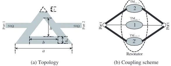
suppressed for it too closes with the operation mode, which will bring more interference. In our design, patch fractal defection with certain feed method is introduced, and based on the above principles, required filter performances such as the dominant mode, higher order mode, single band and dual-band operation can be obtained by controlling the defection location. All of the filters are designed on ceramic substrate with relative dielectric constant of 9.8 and thickness of 1.27 mm, and patch geometric parameters are a = 15 mm, b = 8 mm. I/O feed lines that set at the middle of triangle bevel edge are microstrip lines with characteristic impedance of 50 Ω. The first designed equilateral triangular resonator bandpass filter with tunable operation is shown in Fig. 4, and coupling scheme is shown in Fig. 4(b), where, the deep dark
(a) Topology (b) Coupling scheme
h
a b
P
or
t
1
Po
rt
2
d
t
50
50Ω Ω
2
Po
r
t
Po
r
t
Resonator 1
2'
1 0 1
TM,,
-2 1 1 '
TM,,
-2 1 1
TM,,
1 2 3 4 5 6 -50
-40 -30 -20 -10 0
S21 S11
Magnitude (dB)
Frequency (GHz)
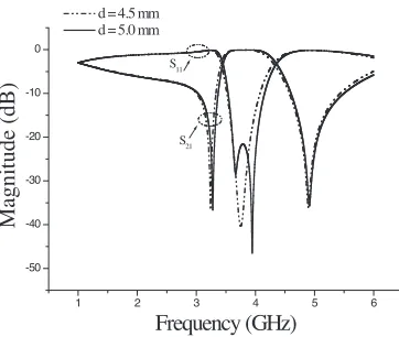
d = 4.5 mm d = 5.0 mm
Figure 5. Frequency responses of the bandpass filter with dominant mode operation.
5 6 7 8 9 10
-40 -35 -30 -25 -20 -15 -10 -5 0
f '1,1,-2
f2,-2,0
f1,1,-2
Magnitude (dB)
Frequency (GHz)
d=1.5 mm
d=2.0 mm
5 6 7 8 9 10
-50 -40 -30 -20 -10 0
S21 S11
Magnitude (dB)
Frequency (GHz)
d=1.5 mm
d=2.0 mm
(a) Resonance (b) Frequency responses
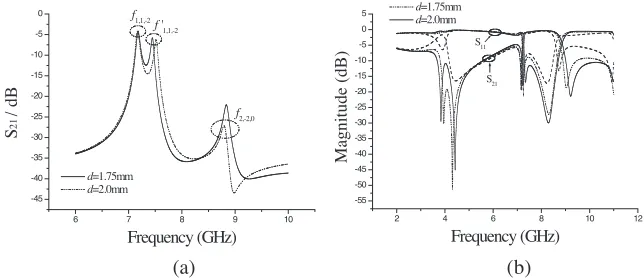
Figure 6. Resonant performance and frequency responses of the bandpass filter with higher order modes operation.
can be seen from Fig. 6(a) that TM1,1,−2mode is splitted by the fractal
defection perturbation, and operation of the neighboring TM2,−2,0
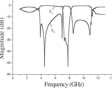
mode is suppressed and becomes very weak, so the designed filter can be seen with multi-mode operation, however, dominantly operates at the higher order dual-mode, Fig. 4shows the filter coupling structure. It can be seen from Fig. 6(b) that the higher order modes coupling filter possesses transmission zeros at both sides of passband, low passband insertion loss of no more than 0.6 dB, and wide stopbands of more than 1.5 GHz. When d= 1.5 mm, the filter centers at 7.27 GHz, and has a relative bandwidth of 11.3%. When more perturbation such as a top triangle cut is introduced, filter operates at the higher order modes and bandwidth can be extended, as shown in Fig. 7. It can be seen that centers at a higher frequency of 7.62 GHz, the bandpass filter is provided with a wider passband with relative bandwidth of about 13.8%, and wider stopbands of more than 3 GHz.
0 2 4 6 8 10 1 14 -60
-50 -40 -30 -20 -10 0
S21 S11
Magnitude (dB)
Frequency (GHz)
2
Figure 7. Frequency responses of the higher order modes operation for the triangular resonator bandpass filter with top triangle cut (d= 1.5 mm,t= 2 mm).
Two types of modified bandpass filters with tunable operation are also presented, as shown in Fig. 8, and single band, dual-band, multi-mode operation are implemented due to the modified perturbation, and the dielectric material and height are the same as the first designed filter. For the bandpass filter as shown in Fig. 8(a), dual-passband with operation frequencies of 3.8 GHz and 7.4GHz (f02 ≈1.95f01) is
(a) (b) a b Po rt 1 Po rt 2 50 50 d h a b P o rt 1 Po rt 2 50 50 d h t Ω Ω Ω Ω
Figure 8. Modified bandpass filter with tunable operation, (a) with trapezoidal defection (h = 4mm), (b) with trapezoidal defection and top triangle cut (h= 4mm,t= 3 mm).
0 2 4 6 10
-50 -40 -30 -20 -10 0 Magnitude (dB) Frequency (GHz)
d=2.75mm,dual-band operation
d=3.0mm, dual-band operation
d=4.0mm, single band operation
(a) (b)
8
2 4 6
-70 -60 -50 -40 -30 -20 -10 0 f1,0,-1 S21 / d B Frequency (GHz) d=2.75mm d=3.0mm d=4.0mm
Figure 9. Resonance and frequency responses of topology Fig. 8(a). (a) Dominant mode resonance of the first passband, (b) Frequency responses.
6 7 8 9 10
-45 -40 -35 -30 -25 -20 -15 -10 -5 0 f2,-2,0
f '1,1,-2
f1,1,-2 S 21 /d B Frequency (GHz) d=1.75mm d=2.0mm
2 4 6 8 10 12
-55 -50 -45 -40 -35 -30 -25 -20 -15 -10 -5 0 5 S21 S11 Magnitude (dB) Frequency (GHz) d=1.25mm d=1.75mm d=2.0mm (a) (b)
TM1,1,−2 (degenerate mode) and TM2,−2,0 operation can be introduced
whend≥1.75 mm, and the 3 dB bandwidth can be extended to about
1.6 GHz, as shown in Fig. 10. All designed filters have high frequency selectivity.
4. CONCLUSION
New patch resonator bandpass filters with tunable operation are proposed to implement wide bands, low passband insertion loss, and transmission zeros at both sides of passband as well as miniaturization. With a fractal defection as perturbation, filter operation frequency and band can be controlled, and filter performances are greatly enhanced for neighboring modes responses weakened and harmonics suppression. The new filters have small sizes, compact and simple configurations as well as high performances, and the interesting new design is very useful for microwave/RF circuit application.
ACKNOWLEDGMENT
This project is supported by China Postdoctoral Science Foundation (20070410236) and South China University of Technology Postdoctoral Science Foundation. The authors thank the anonymous reviewers for their suggestions.
REFERENCES
1. Xiao, J.-K., S. Ma, S. Zhang, and Y. Li, “Novel compact split ring stepped-impedance resonator (SIR) bandpass filters
with transmission zeros,”Journal of Electromagnetic Waves and
Applications, Vol. 21, No. 3, 319–339, 2007.
2. Zhang, J., J.-Z. Gu, B. Cui, and X.-W. Sun, “Compact and harmonic suppression open-loop resonator bandpass filter with
tri-section SIR,”Progress In Electromagnetics Research, PIER 69,
93–100, 2007.
3. Zhao, L.-P., X. Zhai, B. Wu, T. Su, W. Xue, and C.-H. Liang, “Novel design of dual-mode bandpass filter using rectangle
structure,”Progress In Electromagnetics Research B, Vol. 3, 131–
141, 2008.
4. Xiao, J.-K., S.-P. Li, and Y. Li, “Novel planar bandpass filters
using one single patch resonators with corner cuts,” Journal of
5. Xiao, J.-K. and Y. Li, “Novel compact microstrip square
ring bandpass filters,” Journal of Electromagnetic Waves and
Applications, Vol. 20, No. 13, 1817–1826, 2006.
6. Wang, Y.-X., B.-Z. Wang, and J. P. Wang, “A compact square
loop dual-mode bandpass filter with wide stop-band,”Progress In
Electromagnetics Research, PIER 77, 67–73, 2007.
7. Chen, Z.-X., X.-W. Dai, and C.-H. Liang, “Novel mode
dual-band dual-bandpass filter using double square-loop structure,”Progress
In Electromagnetics Research, PIER 77, 409–416, 2007.
8. Helszajn, J. and D. S. James, “Planar triangular resonators with
magnetic walls,”IEEE Trans. Microwave Theoryand Techniques,
Vol. 26, No. 2, 95–100, 1978.
9. Hong, J. S. and S. Li, “Theory and experiment of dual-mode
microstrip triangular-patch resonators and filters,” IEEE Trans.
Microwave Theoryand Techniques, Vol. 52, No. 4, 1237–1243,
2004.
10. Hong, J. S., “Microstrip dual-mode band reject filter,” IEEE
MTT-S Digest, 945–948, 2005.
11. Zhao, L.-P., X.-W. Dai, Z.-X. Chen, and C.-H. Liang, “Novel design of dual-mode dual-band bandpass filter with triangular
resonators,” Progress In Electromagnetics Research, PIER 77,
417–424, 2007.
12. Lugo, C. and J. Papapolymerou, “Bandpass filter design using a microstrip triangular loop resonator with dual-mode operation,”
IEEE Trans. Microwave and Wireless Components Letters,
Vol. 15, No. 7, 475–477, 2005.
13. Xiao, J.-K., Q. Chu, and S. Zhang, “Novel microstrip triangular resonator bandpass filter with transmission zeros and wide bands
using fractal-shaped defection,” Progress In Electromagnetics
Research, PIER 77, 343–356, 2007.
14. Khan, S. N., J. Hu, J. Xiong, and S. He, “Circular fractal
monopole antenna for low VSWR UWB applications,” Progress