Spur Gear Progress Using Rapid Prototyping by Reverse Engineering1 Srinivasa Rao Darimireddi, 2 T.Suresh Prakash
P a g e 1222
Spur Gear Progress Using Rapid Prototyping by
Reverse Engineering
1 Srinivasa Rao Darimireddi, 2 T.Suresh Prakash
1
M.Tech Research Scholar
2
Associate Professor
Swamy Vivekananda Engineering College,Bobbili,Viziangaram District,Andhra Pradesh
Abstract:
In this paper we addressing about Spur gears progress by reverse engineering. Spur gears are important element of power transmission in any mechanical system in which all the stresses should be in design limit Reverse engineering helps in obtaining the geometry of part or product which is not available otherwise. Its application makes it possible to reconstruct the original
component with its drawing and
manufacturing process. The process of duplicating an existing part, subassembly, or product without the aid of drawings, documentation, or a computer model is known as reverse engineering. Reverse engineering is also defined as the process of obtaining a geometric CAD model from 3D points acquired by scanning/ digitizing the existing products. The aim of this paper is to review the reverse engineering process, and its role in the development, refinement and modifications in the existing design of product has been discussed. After a brief introduction, the various stages involved in reverse engineering, and its applications in different fields have been discussed. A brief historical events using reverse engineering
technique have also been discussed at length.
Key Words:
Reverse engineering, reverse engineering stages, scanners. Spur Gears
1. INTRODUCTION
Due to globalization and trade
liberalization, manufacturing companies face tough competition from goods and
services produced in lower wage
Spur Gear Progress Using Rapid Prototyping by Reverse Engineering1 Srinivasa Rao Darimireddi, 2 T.Suresh Prakash
P a g e 1223
inefficiencies. Companies need to create small quantities of highly customized, designed-to-order parts that meet the needs of the global customer. The swift trend toward a multiplicity of finished products with short development and production lead times has led many companies into problems with inventories, overhead, and inefficiencies. They are trying to apply the traditional mass-production approach without realizing that the whole environment has changed. Mass production does not apply to products where the customers require small quantities of highly custom, designed-to-order products, and where additional services and value-added benefits such as product upgrades and future reconfigurations are as important as the product itself. Approaches such as Rapid Prototyping (RP) and Reverse Engineering (RE) are helping to solve some of these problems.
“Reverse engineering (RE) refers to creating a computer-aided design (CAD) model from an existing physical object, which can be used as a design tool for producing a copy of an object, extracting the design concept of an existing model, or reengineering an existing part.” Yau et al. (1993) define RE, as the “process of retrieving new geometry from a manufactured part by digitizing and modifying an existing CAD model”. Abella et al.(1994) described Reverse Engineering (RE) as, “the basic concept of producing a part based on an original or physical model without the use of an engineering drawing”. Reverse engineering is now widely used in
numerous applications, such as
manufacturing, industrial design, and
jewelry design and reproduction For example, when a new car is launched on the market, competing manufacturers may buy one and disassemble it to learn how it was built and how it works. In some situations, such as automotive styling, designers give shape to their ideas by using clay, plaster, wood, or foam rubber, but a CAD model is needed to manufacture the part. As products become more organic in shape, designing in CAD becomes more challenging and there is no guarantee that the CAD representation will replicate the sculpted model exactly.
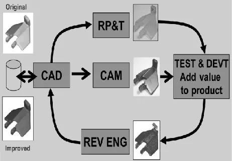
Fig 1 : product development life cycle
Spur Gear Progress Using Rapid Prototyping by Reverse Engineering1 Srinivasa Rao Darimireddi, 2 T.Suresh Prakash
P a g e 1224
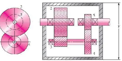
focus on an overview of a power transmission system design, demonstrating how to incorporate the details of each component into an overall design process. A typical two-stage gear reduction box is been used to understand the design process. The design sequence is similar for variations of this particular transmission system.
Fig 2: compound reverted gear train.
Reverse Engineering: Engineering is the
process of designing, , assembling,
manufacturing and maintaining products and systems. There are two types of engineering, forward engineering and reverse engineering. Forward engineering is the traditional process of moving from high-level abstractions and logical designs to the physical implementation of a system. In some situations, there may be a physical part/ product without any technical details, such as drawings, bills-of-material, or without engineering data. The process of duplicating an existing part, subassembly,
or product, without drawings,
documentation, or a computer model is known as reverse engineering. Reverse engineering is also defined as the process of obtaining a geometric CAD model from 3-D
points acquired by scanning/ digitizing existing parts/products.
The process of digitally capturing the physical entities of a component, referred to as reverse engineering (RE), is often defined by researchers with respect to their specific task (Motavalli & Shamsaasef
1996). Abella et al. (1994) described RE as,
“the basic concept of producing a part based on an original or physical model without the use of an engineering drawing”. Yau et al.(1993) define RE, as the “process of retrieving new geometry from a manufactured part by digitizing and modifying an existing CAD model”. Reverse engineering is now widely used in
numerous applications, such as
manufacturing, industrial design, and jewelry design and reproduction For example, when a new car is launched on the market, competing manufacturers may buy one and disassemble it to learn how it was built and how it works. In software engineering, good source code is often a variation of other good source code. In some situations, such as automotive styling, designers give shape to their ideas by using clay, plaster, wood, or foam rubber, but a CAD model is needed to manufacture the part. As products become more organic in shape, designing in CAD becomes more challenging and there is no guarantee that the CAD representation will replicate the sculpted model exactly.
Spur Gear Progress Using Rapid Prototyping by Reverse Engineering1 Srinivasa Rao Darimireddi, 2 T.Suresh Prakash
P a g e 1225
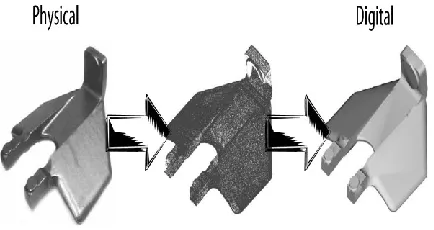
physical-to-digital process depicted in Figure 1.2. Another reason for reverse engineering is to compress product development cycle times. In the intensely competitive global market, manufacturers are constantly seeking new ways to shorten lead times to market a new product. Rapid product development (RPD) refers to
recently developed technologies and
techniques that assist manufacturers and designers in meeting the demands of shortened product development time. For example, injection-molding companies need to shorten tool and die
Fig 3: Physical-to-digital process
Development time drastically. By using reverse engineering, a three-dimensional physical product or clay mock-up can be quickly captured in the digital form, remodeled, and exported for rapid prototyping/tooling or rapid manufacturing using multi-axis CNC machining techniques.
II.APLLICATIONS OF REVERSE
ENGINEERING:
Following are some of the reasons for using reverse engineering:
• The original manufacturer no longer exists, but a customer needs the product,
e.g., aircraft spares required typically after
an aircraft has been in service for several years.
• The original manufacturer of a product no
longer produces the product, e.g., the
original product has become obsolete.
• The original product design
documentation has been lost or never existed.
• Creating data to refurbish or manufacture a part for which there are no CAD data, or for which the data have become obsolete or lost.
• Inspection and/or Quality Control– Comparing a fabricated part to its CAD description or to a standard item.
• Some bad features of a product need to
be eliminated e.g., excessive wear might
indicate where a product should be improved.
• Strengthening the good features of a product based on long-term usage.
• Analyzing the good and bad features of competitors’ products.
• Exploring new avenues to improve product performance and features.
• Creating 3-D data from a model or sculpture for animation in games and movies.
• Creating 3-D data from an individual, model or sculpture to create, scale, or reproduce artwork.
• Architectural and construction
documentation and measurement.
Spur Gear Progress Using Rapid Prototyping by Reverse Engineering1 Srinivasa Rao Darimireddi, 2 T.Suresh Prakash
P a g e 1226
• Generating data to create dental or surgical prosthetics, tissue engineered body parts, or for surgical planning.
• Documentation and reproduction of crime scenes.
The above list is not exhaustive and there are many more reasons for using reverse engineering, than documented above.
III.Rapid Prototyping (RP)
Rapid Prototyping (RP) can be defined as a group of techniques used to quickly fabricate a scale model of a part or
assembly using three-dimensional
computer aided design (CAD) data. What is commonly considered to be the first RP
technique, Stereo lithography, was
developed by 3D Systems of Valencia, CA, USA. The company was founded in 1986, and since then, a number of different RP techniques have become available. Rapid Prototyping has also been referred to as solid free-form manufacturing; computer automated manufacturing, and layered manufacturing. RP has obvious use as a vehicle for visualization. In addition, RP models can be used for testing, such as when an airfoil shape is put into a wind tunnel. RP models can be used to create male models for tooling, such as silicone rubber molds and investment casts. In some cases, the RP part can be the final part, but typically the RP material is not strong or accurate enough. When the RP material is
suitable, highly convoluted shapes
(including parts nested within parts) can be produced because of the nature of RP.
There is a multitude of experimental RP methodologies either in development or used by small groups of individuals. This section will focus on RP techniques that are
currently commercially available,
includingStereolithography (SLA), Selective Laser Sintering (SLS®), Laminated Object Manufacturing (LOM™), Fused Deposition Modeling (FDM), Solid Ground Curing (SGC), and Ink Jet printing techniques.
Methodology of Rapid Prototyping
The basic methodology for all current rapid prototyping techniques can be summarized as follows:
Methodology of Rapid Prototyping
The basic methodology for all current apid prototyping techniques can be summarized as follows:
1. A CAD model is constructed, and then converted to STL format. The resolution can be set to minimize stair stepping.
2. The RP machine processes the .STL file by creating sliced layers of the model.
3. The first layer of the physical model is created. The model is then lowered by the thickness of the next layer, and the
process is repeated until completion of the model.
4. The model and any supports are
Spur Gear Progress Using Rapid Prototyping by Reverse Engineering1 Srinivasa Rao Darimireddi, 2 T.Suresh Prakash
P a g e 1227
IV.THE
GENERIC
PROCESS:
STAGES INVOLVED IN REVERSE
ENGINEERING:
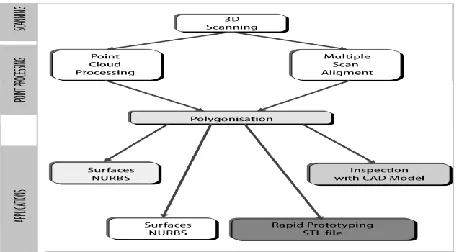
The generic process of reverse engineering is a three-phase process as depicted in Figure 3. The three phases are scanning, point processing, and application specific geometric model development. Reverse engineering strategy must consider the following:
• Reason for reverse engineering a part • Number of parts to be scanned–single or multiple
• Part size–large or small
• Part complexity–simple or complex • Part material–hard or soft
• Part finish–shiny or dull
• Part geometry–organic or prismatic and internal or external
• Accuracy required–linear or volumetric
Figure 4: Reverse engineering – the generic process
Phase 1– Scanning:
This phase is involved with the scanning strategy–selecting the correct scanning technique, preparing the part to be
scanned, and performing the actual scanning to capture information that describes all geometric features of the part such as steps, slots, pockets, and holes. Three-dimensional scanners are employed to scan the part geometry, producing clouds of points, which define the surface geometry. These scanning devices are available as dedicated tools or as add-ons to
the existing computer numerically
controlled (CNC) machine tools. There are two distinct types of scanners, contact and noncontact.
a. Contact Scanners
These devices employ contact probes that automatically follow the contours of a physical surface .In the current market place, contact probe.
Fig 5: Contact scanning touch probe.
Spur Gear Progress Using Rapid Prototyping by Reverse Engineering1 Srinivasa Rao Darimireddi, 2 T.Suresh Prakash
P a g e 1228
materials such as rubber cannot be easily or accurately scanned.
b. Noncontact Scanners:
A variety of noncontact scanning technologies available on the market capture data with no physical part contact. Noncontact devices use lasers, optics, and charge-coupled device (CCD) sensors to capture point data, as shown in Figure. Although these devices capture large amounts of data in a relatively short space of time, there are a number of issues related to this scanning technology.
V .CLASSIFICATION OF GEARS
Figure 6: classification of gears
Spur Gears
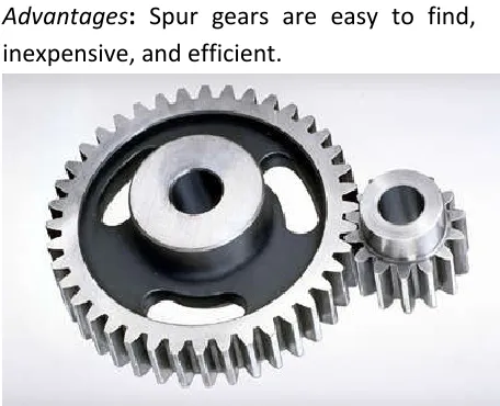
General: Spur gears are the most commonly used gear type. They are characterized by teeth which are perpendicular to the face of the gear. Spur gears are by far the most commonly available, and are generally the least expensive. The basic descriptive geometry for a spur gear is shown in the figure below.
Limitations: Spur gears generally cannot be used when a direction change between the two shafts is required.
Advantages: Spur gears are easy to find, inexpensive, and efficient.
Fig 7: SPUR GEAR
VI. CONCLUSIONS:
Spur Gear Progress Using Rapid Prototyping by Reverse Engineering1 Srinivasa Rao Darimireddi, 2 T.Suresh Prakash
P a g e 1229
reconstructing it as a 3D model. The physical object can be measured manually using gauges, scales & meters or with the help of computers using 3D scanning technologies like CMMs, laser scanners, structured light digitizers or computed tomography. It is a process that can reduce the product development cycle besides cost saving. Effective use of reverse engineering application is expected to penetrate market in the future.
REFERENCES:
[1.]Raja, Vinesh & Fernandes, Kiran J.
(2008), “Reverse Engineering: an
industrial perspective”, Springer series in advanced manufacturing.
[2.]Lee, K.H. & Woo, H. (1998), “Use of
Reverse Engineering method for rapid
product development”,International
Conference on Computers and Industrial Engineering, vol:35, pp. 21-24.
[3.]Cheng, Z.Q., Thackera, J.G., Pilkeya,
W.D.,Hollowellb, W.T., Reagana, S.W. & Sievekaa, E.M.,(2001), “Experiences in Reverse-Engineering of a Finite element
Automobile crash model”, Finite
Elements in Analysis and Design, ELSEVIER. Vol: 37,pp. 843–860.
[4.]Feng, H.Y., Liu, Y. &Xie, F.,
(2001),“Analysis of digitizing errors of a laser scanning system”, Journal of Niranjan et al International Journal of Advanced Engineering Research and Studies E-ISSN2249–8974 IJAERS/Vol. II/
Issue I/Oct.-Dec., 2012/24-28 the
International Socities for Precision Engineering and Nanotechnology, vol: 25: pp.185-191.
[5.]Son, S., Park, H. & Lee, K.H.,
(2002),“Automated laser scanning
system for Reverse Engineering and inspection”, International Journal of Machine Tools & Manufacture, vol: 42, pp. 889-897.
[6.]Bardell, R., Balendran, V. &
Sivayoganathan, K.,(2003), “Accuracy analysis of 3D data collection and free-form modeling methods”, Journal of Materials Processing Technology, vol: 133, pp. 26-33.
[7.]Park, S.C. & Chung, Y.C.,
(2003),“Tool-path generation from
measured data”, Computer-Aided
Design, vol: 35, pp. 467-475.
[8.]Xie, Z., Wang, J. & Zhang, Q., (2005),
“Complete 3D measurement in Reverse Engineering using a multiprobe system”, International Journal of Machine Tools & Manufacture, vol: 45, pp. 1474-1486.
[9.]Lin, Y.P., Wang, C.T. & Tai, K.R.,
(2005), “Reverse Engineering in CAD model reconstruction of customized artificial joint”, Medical Engineering & Physics, vol: 27: pp. 189-193.
[10.] Shadab, Mohammad., Dr.