ISSN (Print) : 2320 – 3765 ISSN (Online): 2278 – 8875
I
nternational
J
ournal of
A
dvanced
R
esearch in
E
lectrical,
E
lectronics and
I
nstrumentation
E
ngineering
(An ISO 3297: 2007 Certified Organization)
Vol. 5, Issue 12, December 2016
V/F control of Induction Motor using Space
Vector Modulation with DC Braking Chopper
C.Priyanka1, O.Sobhana2
M.Tech (PE), Dept. of EEE, VNRVJIET, T.S, India1 Assistant Professor, Dept. of EEE, VNRVJIET, T.S, India2
ABSTRACT: in this paper, speed control analysis of 3-phase induction motor scalar (V/F) control is studied. DC link capacitor inverter fed by 3-ɸ diode rectifier is used as power supply. A closed loop space vector modulation with scalar (v/f) control is used for reference speed generation. A braking chopper is connected in DC bus for limiting DC bus voltage under overhauling load conditions. The paper is explained speed analysis of induction motor by constant v/f ratio under variable load torque. The performance characteristics are illustrated using MATLAB/Simulink.
KEYWORDS: speed control, induction motor, v/f control, SVM, DC link capacitor, braking chopper
I.INTRODUCTION
Variable speed AC Induction motors powered by switching power converters are becoming more popular. These types of drives are designed with front end diode rectifiers for cost reduction and reliability [1]. In these types of low-cost ac drive systems, aluminum electrolytic capacitors are commonly used to balance the difference between the instantaneous input and output power as well as suppress the voltage spikes caused by leakage inductance and switching operations. However, the use of induction motors is challenging because of its complex mathematical model, its non-linear behavior during saturation and the electrical parameter oscillation that depends on the physical influence of the temperature [11-12].
Scalar control technique is very simple motor controller. The most common principle of this kind is the constant V/Hz principle which requires that the magnitude and frequency of the voltage applied to the stator of a motor maintain constant ratio. The stator magnetic field is kept constant by keeping V/F ratio as constant under operating condition [2-3]. When transient response is critical, switching power converters also allow easy control of transient voltage and current applied to the motor to achieve faster dynamic response. The constant V/Hz principle is considered for this application [6].
The power delivered by converter is controlled by switching signals using Pulse Width Modulation Technique. Different PWM techniques, or ways of determining the modulating signal and the switch-on/switch-off instants from the modulating signal, exist. Popular examples are sinusoidal PWM, hysteresis PWM and the relatively new space vector PWM [8]. These techniques are commonly used with three phase Voltage Source power inverters for the control of three-phase AC induction motors [5]. The space vector PWM technique is employed in this application.
ISSN (Print) : 2320 – 3765 ISSN (Online): 2278 – 8875
I
nternational
J
ournal of
A
dvanced
R
esearch in
E
lectrical,
E
lectronics and
I
nstrumentation
E
ngineering
(An ISO 3297: 2007 Certified Organization)
Vol. 5, Issue 12, December 2016
II.MATHEMATICAL MODELING OF INDUCTION MOTOR
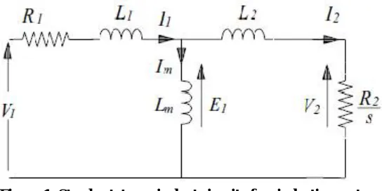
The traditional methods of variable-speed drives are based on the equivalent circuit representation of the motor shown below figure 1 [4].
Figure 1: Steady-state equivalent circuit of an induction motor
From this representation, the following power relationships in terms of motor parameters and the rotor slip can be found [9].
Power in the rotor circuit,
= 3 = 3 =
( ) ………….. 1
The output power
= −3
= (1− )
=
=( ) ………. 2 Where slip
= = ………. 3
P = number of pole pairs
= ……….. 4
= rotar speed
Being the frequency
= 2 /
The developed torque is
=
̀ ⁄ ……….... 5
The slip frequency s , is the frequency of the rotor current and air gap flux is given by
= ̀ = ̀ ̈
Torque
=
( ) =
( )
( ) ………….. 6
Where m is the stator flux linkage due to the air gap flux, the stator impedance is negligible compared to , which is true when is near the rated frequency
III. VOLTS/HERTZ CONTROL
ISSN (Print) : 2320 – 3765 ISSN (Online): 2278 – 8875
I
nternational
J
ournal of
A
dvanced
R
esearch in
E
lectrical,
E
lectronics and
I
nstrumentation
E
ngineering
(An ISO 3297: 2007 Certified Organization)
Vol. 5, Issue 12, December 2016
about the angular speed can be estimated indirectly from the frequency of the supply voltage. The angular speed calculated from the supply voltage frequency according to (7) can be considered as the value of the rotor angular speed if the external load torque is not higher than the breakdown torque.
The mechanical synchronous angular speed is proportional to the frequency of the supply voltage
= 2π /p………. 7 The RMS value of the induced voltage of AC motors is given as
= √2π Nsk φ……….. 8
After neglecting the stator resistance and rewriting the reactance and angular speed as a function of frequency, it is possible to rewrite the maximal torque as
= ………. 9
All constant values in above equation can be replaced with constant C and then the modified expression for the maximal torque is given as
= ……….. 10
The torque will be constant in a wide speed range up to the nominal speed if the ratio of stator voltage and frequency is kept constant
=
This is valid for big machines around the rated frequency
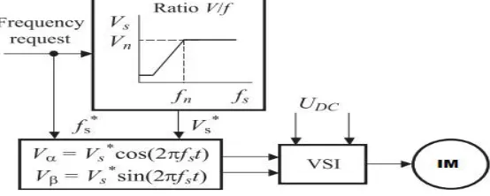
Such a control strategy can be represented by the block diagram illustrated in Fig.2
Figure 2: Block diagram of Volt per Hertz control of AC machines
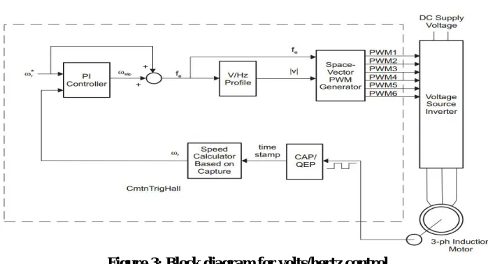
The block diagram for closed loop v/f control by controlling SVPWM technique is shown in Fig. 3. The relation between induced voltage and the flux is
v=k*ϕ……….. 11
ϕ=v/f≈k=constant Where ϕ is the flux
From the block diagram, the reference speed compared to the actual speed then the PI-control generates the slip command i.e.
ISSN (Print) : 2320 – 3765 ISSN (Online): 2278 – 8875
I
nternational
J
ournal of
A
dvanced
R
esearch in
E
lectrical,
E
lectronics and
I
nstrumentation
E
ngineering
(An ISO 3297: 2007 Certified Organization)
Vol. 5, Issue 12, December 2016
Figure 3: Block diagram for volts/hertz control
From the last equation, it follows that if the ratio V/ƒ remains constant for any change in ƒ, then flux remains constant and the torque becomes independent of the supply frequency.
Both open and closed-loop control of the speed of an AC induction motor can be implemented based on the constant V/Hz principle.
In this case, the supply frequency is determined based on the desired speed and the assumption that the motor will roughly follow its synchronous speed. The error in speed resulted from slip of the motor is considered acceptable. The three reference voltages are
= sin ( )……….. 13
= sin ( −120 )…….… 14
= sin ( −240 )………. 15
The easy way to find the resultant vector from available three vectors by transforming three phases to two phase in d-q plane i.e.
= 0 120 240
0 120 240 …………..16
Hence it easy way to find the reference vector magnitude |Vref| and its angle 'α ' can be estimated using above eqn as
< = + < …………..17 The inverter phase voltages can be modeled as
=
2 −1 −1
−1 2 −1
−1 −1 2
………..18
Where is DC-link voltage and , and are the PWM pulses for three phase inverter that are connected to positive side of the DC-link voltage. These three phase voltages of inverter are given to the induction motor to check the dynamic behavior of machine.
IV.SPACE VECTOR MODULATION
Theory of Space vector pulse width modulation
When three phase supply is given to the stator of the induction machine, a three phase rotating magnetic field is produced. Due to this field flux, a three phase rotating voltage vector is generated which lags the flux by 90º. This field can also be realized by a logical combination of the inverter switching which is the basic concept of SVPWM [7].
Realization of voltage space phasor
ISSN (Print) : 2320 – 3765 ISSN (Online): 2278 – 8875
I
nternational
J
ournal of
A
dvanced
R
esearch in
E
lectrical,
E
lectronics and
I
nstrumentation
E
ngineering
(An ISO 3297: 2007 Certified Organization)
Vol. 5, Issue 12, December 2016
is ON. These switching state vectors have equal magnitude but 60º apart from each other. These vectors can be written in generalized form as follows:
= = 1, 2, … ,6
0 = 0, 7
Where k = inverter state number. Vdc = dc link voltage of the inverter
The inverter state vectors can be drawn as shown in fig. 4.
Figure 4: Inverter switching state vectors
The space bounded by two inverter space vectors is called a sector. So the plane is divided into six sectors each spanning 60º. In a balanced three phase system the voltage vectors are 120º apart in space and are represented by rotating vectors, whose projections on the fixed three phase axes are, sinusoidal waves. The reference vector is assumed to be rotating in counter-clockwise direction with respect to ds-axis (α-axis) as shown in fig .4 through six sectors. The reference space vector can be synthesized by a combination of eight state vectors and is constant in magnitude at switching instant ts in case the switching frequency much higher than the output frequency. In a time average sense
thereference vector at that instant can be approximated by two active voltage states of the inverter. For only certain amount of time these states are valid.
∗= + = 0, 1, 2, … … … ,19
In SVPWM, it is assumed that the space phasor of stator voltage ∗, is moving in α-β plane with constant angular
velocity describing approximately a circular path. The basis of SVPWM scheme is to sample the ∗at sufficiently high rate, in between the sampling instants the vector is assumed to be constant in magnitude as shown in fig 5.
Figure 5: Reference vector in sector 1
In sector 1, the space voltage vector V1 is along α-axis, V2 makes an angle 60º to V1 and at a particular instant Vs* is
making an angle γ w.r.t V1. To generate the reference space vector in sector 1, the switching state vector V1 is applied
for an interval t1, V2 for t2 and the two zero vectors V0, V7 for interval t0, t7 respectively. So the total sampling interval
ts can be written as:
ISSN (Print) : 2320 – 3765 ISSN (Online): 2278 – 8875
I
nternational
J
ournal of
A
dvanced
R
esearch in
E
lectrical,
E
lectronics and
I
nstrumentation
E
ngineering
(An ISO 3297: 2007 Certified Organization)
Vol. 5, Issue 12, December 2016
Resolving Vs* and V1, V2along the α-β axis, and by equating voltage-time integrals we get:
| ∗| = | | + | | cos
3… … … .21
| ∗| = | | sin ……….….22
Pulse pattern generation
In order to obtain minimum switching frequency, it is desired that only one phase of the inverter changes state from + /2 to – /2 while changing the switching vectors. So the arrangement of the switching sequence should be such that the transition from one state to the next state is performed by switching only one inverter phase. The mean values of the phase to center tap voltages (VA0, VB0, and VC0) can be evaluated, averaging over one sampling period ts as
follows:
=
2 −2 + + + 2
=
2 −2 − + +2
= − − − + ……….. 23 Substituting the values of t1, t2 in above three equations
=
√3 +3
= −
6
=− ………….. 24
The mean value of the phase voltages obtained by SVPWM technique has triple harmonics which is eliminated in line voltage. The peak value of the line voltage is 15% more than that in sine PWM at maximum modulation index, so this method of PWM generation gives better utilization of dc bus voltage for inverter.
V.SIMULATION RESULTS
The performance of the Volts/Hertz control technique for speed control three-phase induction motor is validated by MATLAB/Simulink software. Fig 6 shows the simulation circuit of block diagram of V/F control technique with Space Vector Modulation scheme.
Figure 6: simulation circuit of proposed V/F controlled induction motor
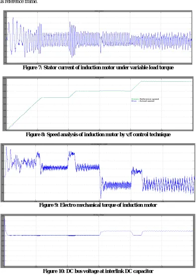
The simulation analysis characteristics of the speed control of three-phase induction motor using scalar (v/f) control technique are given in following figures. The induction motor was simulated with base speed of 1800rpm and variable reference speed of 1200rpm and 1500 rpm at 1 and 2secs respectively. A variable load torque had been applied at successive intervals of 0.5 and 1.5 sec of magnitude of 11and -11Nm.
ISSN (Print) : 2320 – 3765 ISSN (Online): 2278 – 8875
I
nternational
J
ournal of
A
dvanced
R
esearch in
E
lectrical,
E
lectronics and
I
nstrumentation
E
ngineering
(An ISO 3297: 2007 Certified Organization)
Vol. 5, Issue 12, December 2016
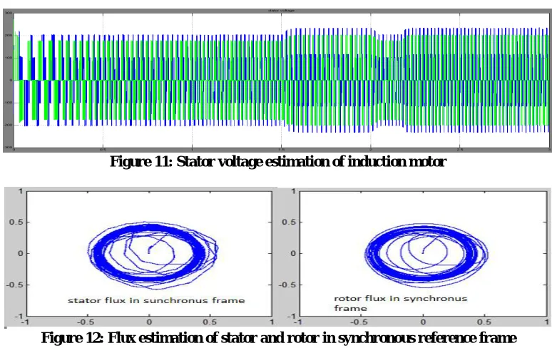
estimation graph was shown in figure 11. Flux estimation graphs are shown in figure 12 for both stator and rotors in synchronous reference frame.
Figure 7: Stator current of induction motor under variable load torque
Figure 8: Speed analysis of induction motor by v/f control technique
Figure 9: Electro mechanical torque of induction motor
ISSN (Print) : 2320 – 3765 ISSN (Online): 2278 – 8875
I
nternational
J
ournal of
A
dvanced
R
esearch in
E
lectrical,
E
lectronics and
I
nstrumentation
E
ngineering
(An ISO 3297: 2007 Certified Organization)
Vol. 5, Issue 12, December 2016
Figure 11: Stator voltage estimation of induction motor
Figure 12: Flux estimation of stator and rotor in synchronous reference frame
VI.CONCLUSION
Speed regulation of three-phase induction motor was difficult under variable load torque conditions. In this paper, v/f control technique for speed control of induction motor using space vector modulation technique is proposed. Mathematical modeling of induction motor was also described. A typical space vector modulation technique was designed for two-level voltage source converter. Three-phase diode rectifier is used across power supply. For regulation DC bus voltage a DC breaking chopper under abnormal load conditions. Simulation analysis is carried out for proposed system to describe performance characteristics. The proposed concept is fully validated and results are described in section V.
REFERENCES
[1] Altivar 21 User’s Manual, Schneider Electric Industries S.A.S., RueilMalmaison, France, 2006.
[2] Novak, Peter (May 1, 2009). "The Basics of Variable-Frequency Drives" EC&M. Retrieved Apr 18, 2012.
[3] K. Inazuma, H. Utsugi, K. Ohishi, and H. Haga, “High-power-factor single-phase diode rectifier driven by repetitively controlled IPM motor,” IEEE Trans. Ind. Electron., vol. 60, no. 10, pp. 4427–4437, Oct. 2013.
[4] MarijaMirošević, “The Dynamics of Induction Motor Fed Directly from the Isolated Electrical Grid,” INTECH Open Science Open Mind, Web Link: http://dx.doi.org/10.5772/49973 2012.
[5] Rashid, “Power electronic; Circuit Devices and Applications,” Third Edition Pearson Education, Inc., 2007.
[6] Alfredo, Thomas A. Lipo and Donald W. Novotny, “A New Induction Motor V/f Control Method Capable of High-Performance Regulation at Low Speeds,” IEEE Trans. on Ind. Appl., vol. 34, no. 4, pp. 813-819, July. 1998.
[7] G. Narayanan, Di Zhao and Harish K. Krishnamurthy, “Space Vector Based Hybrid PWM Techniques for Reduced Current Ripple,” IEEE Trans. on Ind. Electron, vol. 55, no. 4, pp. 1614-1627, April. 2008.
[8] L. Malesani, L. Rossetto, P. Tenti, and P. Tomasin, “AC/DC/AC PWM converter with reduced energy storage in the DC link,” IEEE Trans. Ind. Appl., vol. 31, no. 2, pp. 287–292, Mar./Apr. 1995.
[9] H. Kim, M. C. Harke, and R. D. Lorenz, “Sensorless control of interior permanent-magnet machine drives with zero-phase lag position estimation,” IEEE Trans. Ind. Appl., vol. 39, no. 6, pp. 1726–1733, Nov./Dec. 2003.
[10] Alfredo, Thomas A. Lipo and Donald W. Novotny, “A New Induction Motor V/f Control Method Capable of High-Performance Regulation at Low Speeds,” IEEE Trans. on Ind. Appl., vol. 34, no. 4, pp. 813-819, July. 1998.
[11] S. H. Kim, C. H. Choi, and J. K. Seok, “Voltage disturbance state-filter design for precise torque-controlled interior permanent magnet synchronous motors,” in Proc. IEEE Energy Convers. Congr.Expo. Conf., 2011, pp. 2445–2451.