A Control Scheme to Improve Overall
Efficiency of Grid Connected Cascaded PV
Modules
D.Hemalatha1, A. Nagamani2, M. Naveen Babu3
M.Tech, Dept. of EEE, Tadipatri Engineering College, Affiliated to JNTUA, AP, India1
Assistant Professor, Dept. of EEE, Tadipatri Engineering College, Affiliated to JNTUA, AP, India2
Assistant Professor and HOD, Dept, of EEE, Tadipatri Engineering College, Affiliated to JNTUA, AP, India3
ABSTRACT: Due to the possibility of providing energy with much less dependence on the fossil fuels, renew-competent energy sources, in specified sun photovoltaic (PV) conversion have received elevated acceptance and progress in latest times. Big benefits of PV panels comprise easy and trustworthy power production and suitability for disbursed iteration. In addition the costs for photovoltaic modules is drastically lowering. To comprehend this issue, a control plan with modulation compensation scheme is likewise proposed. A modular cascaded H-bridge multilevel inverter topology for single- or three-phase grid-connected PV systems is presented in this paper. The panel mismatch issues are addressed to show the necessity of individual MPPT control, and a control scheme with distributed MPPT control is then proposed. The distributed MPPT control scheme can be applied to both single-and three-phase systems. A three-phase modular cascaded multilevel inverter proto-type has been built. Each H-bridge is connected to a solar panel. The modular design will increase the flexibility of the system and reduce the cost as well. Simulation and experimental results are provided to demonstrate the developed control scheme.
.
I. INTRODUCTION
Because of the lack of fossil fuels and natural causes created by ordinary power era, renewable energy, especially sun oriented energy, has turned out to be extremely well known. Solar electric-energy demand has become reliably by 20%–25% for each annum in the course of recent years, and the development is for the most part in system associated applications. With the exceptional market development in grid associated photovoltaic (PV) systems, there are expanding interests in grid associated PV arrangements.
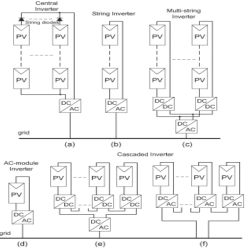
Fig.1. Configurations of PV systems. (a) Central inverter. (b) String inverter.(c) Multi string inverter. (d) AC-module inverter. (e) Cascaded dc/dc converter. (f) Cascaded dc/ac inverter.
Cascaded inverters comprise of a few converters associated in arrangement; in this way, the high power and/or high voltage from the mix of the numerous modules would support this topology in medium and huge grid associated PV systems. There are two sorts of cascaded inverters. Fig. 1(e) demonstrates a cascaded dc/dc converter association of PV modules. Each PV module has its own particular dc/dc converter, and the modules with their related converters are still associated in arrangement to make a high dc voltage, which is given to a rearranged dc/ac inverter. This methodology consolidates parts of string inverters and ac module inverters and offers the benefits of individual module maximum power point (MPP) tracking (MPPT), however it is not so much exorbitant but rather more productive than ac module inverters. Be that as it may, there are two power transformation stages in this design. The modular cascaded H-bridge multilevel inverter, which requires an isolated dc source for every H-bridge, is one dc/ac cascaded inverter topology. The different dc links in the multilevel inverter make autonomous voltage control conceivable. As an outcome, individual MPPT control in each PV module can be accomplished, and the energy reaped from PV panels can be maximized. In the interim, the particularity and ease of multilevel converters would position them as a prime hopeful for the up and coming era of efficient, robust, and reliable grid connected solar power electronics.
A measured cascaded H-bridge multilevel inverter topology for single-or three-stage grid associated PV systems is exhibited in this paper. The panel mismatches issues are tended to demonstrate the need of individual MPPT control, and a control plan with circulated MPPT control is then proposed. The distributed MPPT control plan can be connected to both single and three-stage systems. What's more, for the introduced three-stage grid associated PV system, if each PV module is worked at its own particular MPP, PV mismatches may acquaint unequal power supplied with the three-stage multilevel inverter, prompting unequal infused grid current. To adjust the three-three-stage grid current, modulation compensation is additionally added to the control system.
II. SYSTEM DESCRIPTION
H-bridge can be fed by a PV panel or a short string of PV panels. The cascaded multilevel inverter is associated with the grid through L channels, which are used to decrease the exchanging music in the current. By various mixes of the four switches in each H-bridge module, three output voltage levels can be created: −vdc, 0, or +vdc. A cascaded multilevel inverter with n information sources will give 2n + 1 levels to orchestrate the air conditioner output waveform. This (2n + 1) - level voltage waveform empowers the diminishment of sounds in the incorporated current, lessening the measure of the required output channels. Multilevel inverters too have different points of interest, for example, diminished voltage weights on the semiconductor switches and having higher productivity when contrasted with other converter topologies.
Fig. 2. Topology of the modular cascaded H-bridge multilevel inverter for grid-connected PV systems.
III. PANEL MISMATCHES
PV mismatch is an imperative issue in the PV system. Due to the unequal got irradiance, diverse temperatures, and maturing of the PV panels, the MPP of each PV module might be diverse. In the event that each PV module is not controlled autonomously, the productivity of the general PV system will be diminished.
In a three-phase grid-connected PV system, a PV mismatch may cause more problems. Aside from decreasing the overall efficiency, this could even introduce unbalanced power supplied to the three-phase grid-connected system. If there are PV mismatches between phases, the input power of each phase would be different. Since the grid voltage is balanced, this difference in input power will cause unbalanced current to the grid, which is not allowed by grid standards. For example, to unbalance the current per phase more than 10% is not allowed for some utilities, where the percentage imbalance is calculated by taking the maximum deviation from the average current and dividing it by the average current.
To tackle the PV mismatch issue, a control plan with individual MPPT control and balance pay is proposed. The points of interest of the control plan will be examined in the tracking segment.
IV. CONTROL SCHEME
A. DISTRIBUTED MPPT CONTROL
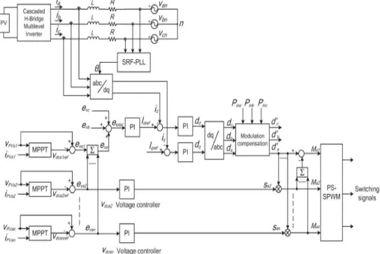
MPPT control of the three-stage cascaded H-bridge inverter is appeared in Fig. 3. In every H-bridge module, a MPPT controller is added to create the dc-link voltage reference. Every dc-link voltage is contrasted with the comparing voltage reference, and the whole of all mistakes is controlled through an aggregate voltage controller that decides the current reference Idref . The receptive current reference Iqref can be set to zero, or if receptive power pay is required, Iqref can additionally be
given by a responsive current adding machine . The synchronous reference outline stage bolted circle (PLL) has been used to discover the stage edge of the grid voltage. As the exemplary control plan in three-stage systems, the grid streams in abc directions are changed over to dq organizes and controlled through proportional–integral (PI) controllers to produce the adjustment record in the dq facilitates, which is then changed over back to three stages.
The disseminated MPPT control plan for the single-stage system is about the same. The aggregate voltage controller gives the greatness of the dynamic current reference, and a PLL gives the recurrence and stage point of the dynamic current reference. The present circle then gives the tweak list. To make each PV module work at its own MPP, take stage an as a case; the voltages vdca2 to vdcan are controlled exclusively through n − 1 circles. Every voltage controller gives the regulation record extent of one H-bridge module in stage a. After increased by the regulation record of stage a, n − 1 regulation records can be gotten. Additionally, the regulation record for the primary H-bridge can be acquired by subtraction. The control plans in stages b also, c is just about the same. The main distinction is that all dc-link voltages are directed through PI controllers, and n adjustment record extents are acquired for every stage.
Fig. 3. Control scheme for three-phase modular cascaded H-bridge multilevel PV inverter.
A phase-shifted sinusoidal pulse width modulation switching scheme is then connected to control the switching devices of each H-bridge. The incremental conductance technique has been utilized in this paper. It lends itself well to computerized control, which can effectively monitor past estimations of voltage and current and settle on all choices.
B. MODULATION COMPENSATION
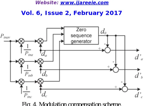
Fig. 4. Modulation compensation scheme.
In this manner, the modulation compensation block, as appeared in Fig. 6, is added to the control arrangement of three-stage modular cascaded multilevel PV inverters. The key is the manner by which to overhaul the balance record of every stage without expanding the complexity of the control system. To start with, the unequal power is weighted by proportion rj,
This is ascertained as
Where Pinj is the info power of stage (j = a, b, c), and Pinav is the normal info power. At that point, the infused zero arrangement adjustment file can be produced as
Where dj is the adjustment record of stage (j = a, b, c) and is dictated by the present circle controller. The adjustment record of every stage is redesigned by
Just straightforward estimations are required in the plan, which won't build the many-sided quality of the control system. A case is displayed to demonstrate the adjustment remuneration plot all the more unmistakably. Expect that the information power of each stage is unequal
By infusing a zero succession tweak list at t = 1 s, the adjusted tweak file will be redesigned, as appeared in Fig. 7. It can be seen that, with the remuneration, the overhauled balance record is uneven relative to the power, which implies that the output voltage (vjN) of the three-stage inverter is uneven; however this creates the sought adjusted grid current.
V. SIMULATION RESULTS
To confirm the proposed control plot, the three-stage grid connected PV inverter is mimicked in two distinctive conditions. In the first place, all PV panels are worked under the same irradiance S = 1000 W/m2 and temperature T =
25 ◦C. At t = 0.8 s, the sun powered irradiance on the first and second panels of stage a declines to 600 W/m2, and that
FIG 5:dc link voltage of modules 1 and 2.
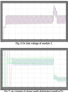
Fig. 6 Dc link voltage of module 3.
Fig 8.dc link voltages of phase b with distributed MPPT (T=25)
Fig 9 Power extracted from PV panels with distributed MPPT
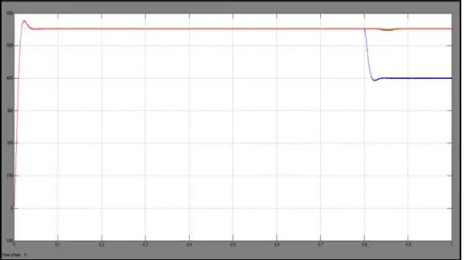
Fig 11. Three-phase inverter output voltage waveforms with modulation compensation.
Fig 12. Three-phase grid current waveforms with modulation compensation.
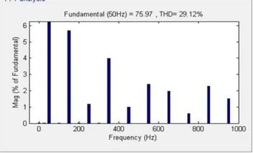
Fig 14 THD of grid current
EXTENTION RESULTS
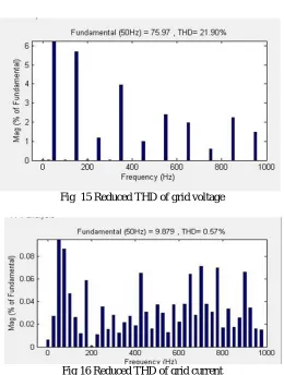
Fig 15 Reduced THD of grid voltage
Fig 16 Reduced THD of grid current
VI. CONCLUSION
are controlled independently. Thus, a distributed MPPT control scheme for both single and three-phase PV systems has been applied to increase the overall efficiency of PV systems. For the three-phase grid-connected PV system, PV mismatches may introduce unbalanced supplied power, resulting in un-balanced injected grid current. A modulation compensation scheme, which will not increase the complexity of the control system or cause extra power loss, is added to balance the grid current.
REFERENCES
1. M. Carrasco et al., “Power-electronic systems for the grid integration of renewable energy sources: A survey,” IEEE Trans. Ind. Electron., vol. 53, no. 4, pp. 1002–1016, Jun. 2006.
2. S. B. Kjaer, J. K. Pedersen, and F. Blaabjerg, “A review of single-phase grid connected inverters for photovoltaic modules,” IEEE Trans. Ind.
Appl., vol. 41, no. 5, pp. 1292–1306, Sep./Oct. 2005.
3. M. Meinhardt and G. Cramer, “Past, present and future of grid connected photovoltaic- and hybrid power-systems,” in Proc. IEEE PES Summer
Meet., 2000, vol. 2, pp. 1283–1288.
4. M. Calais, J. Myrzik, T. Spooner, and V. G. Agelidis, “Inverter for single-phase grid connected photovoltaic systems—An overview,” in Proc. IEEEPESC, 2002, vol. 2, pp. 1995–2000.
5. M. A. Myrzik and M. Calais, “String and module integrated inverters for single-phase grid connected photovoltaic systems—A review,” in
Proc.IEEE Bologna Power Tech Conf., 2003, vol. 2, pp. 1–8.
6. F. Schimpf and L. Norum, “Grid connected converters for photovoltaic, state of the art, ideas for improvement of transformerless inverters,” in
Proc. NORPIE, Espoo, Finland, Jun. 2008, pp. 1–6.
7. B. Liu, S. Duan, and T. Cai, “Photovoltaic DC-building-module-based BIPV system—Concept and design 8. considerations,” IEEE Trans. PowerElectron., vol. 26, no. 5, pp. 1418–1429, May 2011.
9. M. Tolbert and F. Z. Peng, “Multilevel converters as a utility interface for renewable energy systems,” in Proc. IEEE Power Eng. Soc. Summer