ISSN (Print) : 2320 – 3765 ISSN (Online): 2278 – 8875
I
nternational
J
ournal of
A
dvanced
R
esearch in
E
lectrical,
E
lectronics and
I
nstrumentation
E
ngineering
(A High Impact Factor, Monthly, Peer Reviewed Journal) Website: www.ijareeie.com
Vol. 7, Issue 2, February 2018
Density Based Smart Lighting System Using
IoT
N.S.Yoganathan1, G.Lakshmi Priya2, R.Monisha3, A.Lavanya4, S.Kowsalya5
Assistant Professor, Dept. of ECE, Sona College of Technology, Salem, Tamilnadu, India1
UG Student, Dept. of ECE, Sona College of Technology, Salem, Tamilnadu, India2,3,4,5
ABSTRACT : In this modern era, the world is entirely dependent on electricity which is a major source of energy. Hence in the world of huge population, Conservation of energy is highly indispensible. Therefore, it is the responsibility of each and every individual to work for the conservation of Electricity. Lighting Systems is one of the key components of smart cities where energy will be used very efficientlyby turning the lights/ fans ON and OFF at the right time as needed.It plays a vital role in homes, offices, industrial sectors, urban and rural areas. The purpose of this project is to save the power used in places like classrooms, auditoriums, conference halls, public meetings, etc. When a particular number of persons enters the monitored area, the load will be activated and also the data will be sent to the cloud for storage and analysis where reports can be generated to show the duration when the lights/ fans are ON along with the number of occupants in the room.
KEYWORDS- Lighting Systems, Arduino, Passive Infrared Radiation(PIR)Sensor, Esp8266 Wifi Module, ThingSpeak.
I. INTRODUCTION
Nowadays, energy consumption is more in residential and commercial areas. It is because of the inefficient usage of electrical loads. Smart lighting is a lighting technology designed for energy efficiency. This may include high energy fixtures and automated controls that make adjustments based on conditions such as occupancy or daylight availability.It is the good way which enables to minimize and save light by allowing the householder to control cooling, heating, lighting and the control of appliances remotely. This ability saves energy and provides a level of comfort and convenience.
The concept of smart lighting also involves utilizing natural light from the sun to reduce the use of manmade lighting and also the motion of people when they leave/enter a room. In the world, almost 20% of energy is used for lighting and around 6% is for greenhouse emissions. Different areas of lighting are commercial, residential, industrial and outdoor lighting. Each area has its own needs and power requirements for lighting using different sensors
In the United States, 65 percent of energy consumption is used for commercial and industrial sectors and 22 percent of this is used for lighting. Hence, for low cost and high efficiency, Wireless sensor networks is used.But it is so crucial to use the smart lighting system by automatically switching on/off or dim the lights when needed without disturbing the normal operation of the working environment. By using motion sensors like PIR, IR and dual technology sensors, light can be controlled without affecting the normal working environment which helps to reduce energy consumption by switching on/off the light only when needed and by using LED, the carbon dioxide emission can be reduced.
ISSN (Print) : 2320 – 3765 ISSN (Online): 2278 – 8875
I
nternational
J
ournal of
A
dvanced
R
esearch in
E
lectrical,
E
lectronics and
I
nstrumentation
E
ngineering
(A High Impact Factor, Monthly, Peer Reviewed Journal) Website: www.ijareeie.com
Vol. 7, Issue 2, February 2018
II. LITERATURE SURVEY
Literature review is nothing but the study of the previously existing methodologies and also a collection of the information needed to improve our task. There are several journal papers that have been published for reducing the power consumption based on smart lighting system which is the hot core of the research. So many efforts are made to improve the existing approaches for better efficiency and low power consumption.
Soyoung Hwang[1] proposed a remote monitoring and controlling system which is based on ZIGBEE networks. In this method, the real time monitoring is implemented with JMF.
Richu Sam Alex[2] proposed a system which reduces the power consumption of street lighting system. This system is fully automated. It also uses Zigbee so that the control station can analyze all the performance of the system.
Daeho Kim[3] worked on Smart LED lighting system by using Infrared and Ultrasonic sensors together. Here human presence is detected by IR sensor and continuous tracking is possible by Ultrasonic sensor. Output based on human tracking data which is obtained by both the sensors are responsible for determining the On/Off control of the lighting system.
Raja R[4] uses a smart sensor networks in DC electrical appliances like lighting, helps for monitoring of energy usage. Dimming of light can be achieved by using appropriate protocol that helps in energy saving.
B.K. Subramanyam[5] have developed a model which provides smart lighing system on streets which is mainly solar based. More power and energy is saved by using LDR and IS sensors.
Michele Mango[6] proposed a low cost, wireless, adaptable sensor based smart lighting system which makes use of PIR sensors and motion sensors. It is helpful for controlling the light intensity. Replacing the traditional lamps by LED makes 44% energy saving.
In this paper, we are planning to propose a system which makes use of two PIR sensors for detecting the human presence along with arduino uno which makes the system as Bidirectional Counter .The system reduces the power consumption by determining On/Off control of the lighting system based on particular count. We also used a ESP8266 for analyzing and visualizing the system performance.
III. SENSORS
A Sensor is a device or subsystem whose function is to detect the environment changes and send the information to other electronic equipments, frequently a computer processor. It is always used with other electronic equipments, whether as simple as the light or as complex as the computer .
A Sensors is the heart of the smart lighting in the current rsearch. In order to reduce the electricity bills, smart lighting makes use of sensors.Sensors like ambient lighting sensors, proximity sensor or photodiodes can also be used for smart lighting. A complete sensor consists of a motion detector, an electronic control circuit and a controllable switch or relay. The detector senses motion and determines whether there are occpants in the space.
The control unit uses the signal from timer to activate the switch or relay to turn equipment on or off. Smart lighting systems can also be controlled using the internet to adjust lightbrightness and schedules.
IV. DESCRIPTION
ISSN (Print) : 2320 – 3765 ISSN (Online): 2278 – 8875
I
nternational
J
ournal of
A
dvanced
R
esearch in
E
lectrical,
E
lectronics and
I
nstrumentation
E
ngineering
(A High Impact Factor, Monthly, Peer Reviewed Journal) Website: www.ijareeie.com
Vol. 7, Issue 2, February 2018
channel relay board. We can also use four channel relay board instead of two channel relay board to switch four different loads at a same time.
V. BLOCK DIAGRAM
VI. WORKING PRINCIPLE
When two PIR sensors are connected with an arduino, the arduino acts as a bidirectional counter. Whenever the motion is detected by the PIR sensor, its output pin goes high (around 3.3V). The high signal from the PIR is fed to the arduino module. The main purpose of the arduino module is to control the entire circuit based on people’s occupancy and to count the number of persons entering. Thus once, the persons count has reached the desired level(Say 5), the 2 channel relay board is activated by the signal from arduino and hence the circuit gets closed. Then the relay activates the external loads like lights, fans etc., The informations(like number of persons entered and the status of the light) are transmitted to the ThingSpeak App via ESP8266 Wifi Module for analysis. The datas are displayed in the form of graph.
VII. COMPONENTS A. PIR SENSOR
ISSN (Print) : 2320 – 3765 ISSN (Online): 2278 – 8875
I
nternational
J
ournal of
A
dvanced
R
esearch in
E
lectrical,
E
lectronics and
I
nstrumentation
E
ngineering
(A High Impact Factor, Monthly, Peer Reviewed Journal) Website: www.ijareeie.com
Vol. 7, Issue 2, February 2018
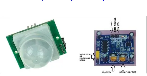
Fig .1 FRONT AND REAR SIDE VIEW OF PIR SENSOR
The term passive refers to the fact that PIR devices do not generate or radiate any energy for detection purpose. It can not detect or measure heat; instead they detect the infrared radiation emitted or reflected from an object. They work entirely by detecting the energy released from an objects. All object with the temperature above 0 degree emits heat energy in the form of radiation. Generally, this radiation is not visible to human eye because its wave length is in infrared range. But it can be detected by electronic components design for such a purpose.
Different mechanisms can be used to focus the distant infrared energy on to the sensor surface. Fresnel lens is a type of compact lens. The design allows the construction of lenses of large apertures and short focal length without the mass and volume of the material that would be required by a lens of conventional design. A fresnel lens can capture more oblique light from a light source, thus allowing light from a lighthouse equipped to be visible over greater distances. They are two types of fresnel lens: imaging and non-imaging. Imaging fresnel lenses use segments with curved cross sections and produce sharp images. Non imaging lenses have segments with flat cross section and donot produce sharp images.The PIR sensors uses spherical fresnel lens which consists of ring shaped segments that produces a sharp images.
FEATURES
Automatic induction
Triggered in two ways
1) Not repeatable trigger: If the sensor output is high and the delay time is over, the output is
automatically changed from high level to low level.
2) Repeatable Trigger:If the sensor output is high and also if there is anhuman activity in its sensing
range, the output will always remains high until the people left after the delay will be high level goes low.
Wide operating voltage range
Micropower consumption
B. ARDUINO UNO
ISSN (Print) : 2320 – 3765 ISSN (Online): 2278 – 8875
I
nternational
J
ournal of
A
dvanced
R
esearch in
E
lectrical,
E
lectronics and
I
nstrumentation
E
ngineering
(A High Impact Factor, Monthly, Peer Reviewed Journal) Website: www.ijareeie.com
Vol. 7, Issue 2, February 2018
Fig.2 ARDUINO UNO WITH ATMEGA328
PIN DEFINITION
PIN NUMBER FUNCTION
0-13 Digital I/O
A0-A5 Analog I/O
3
PWM outputs 5
6 9 10 11 Vin
POWER Gnd
5V 3.3V RESET
IOREF
C. ESP8266 WIFI MODULE
The ESP8266 is a low cost Wi-Fi chip with TCP/IP stack and MCU(Microcontroller unit) capability. This small module allows the microcontroller to connect to a Wi-Fi network and makes a simple TCP/IP connections using AT commands.The first chip was developed by western makers in August 2014 with the ESP-01 module.
ISSN (Print) : 2320 – 3765 ISSN (Online): 2278 – 8875
I
nternational
J
ournal of
A
dvanced
R
esearch in
E
lectrical,
E
lectronics and
I
nstrumentation
E
ngineering
(A High Impact Factor, Monthly, Peer Reviewed Journal) Website: www.ijareeie.com
Vol. 7, Issue 2, February 2018
A) PIN DEFINITION
NAME FUNCTION
VCC Power 3.0~3.6V
GND Ground
RESET External Reset
CH_PD Enable chip
TX Transmitter
RX Receiver
GPIO0 General Purpose I/O
GPIO1
B) LIST OF AT COMMANDS
COMMANDS DESCRIPTION
AT General Test
AT+RST Restart the module
AT+GMR Check firmware version
AT+CWMODE Wi-Fi mode
AT+CWLAP List the AP
AT+CWQAP Quit the AP
AT+CIFSR Get IP address
AT+CIPMUX Set multiple connection
To connect the ESP8266 to the available wifi, the following connections has to given and check the response on the serial monitor of ARDUINO IDE software with the baudrate of 115200 and choose both NL and CR option.
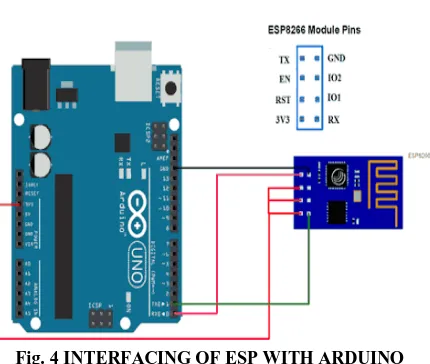
C) INTERFACING OF ESP8266 WITH ARDUINO
ESP8266 ARDUINO
TX TX(PIN 1)
RX RX(PIN 0)
CH_PD and VCC 3.3V
GND GND
ISSN (Print) : 2320 – 3765 ISSN (Online): 2278 – 8875
I
nternational
J
ournal of
A
dvanced
R
esearch in
E
lectrical,
E
lectronics and
I
nstrumentation
E
ngineering
(A High Impact Factor, Monthly, Peer Reviewed Journal) Website: www.ijareeie.com
Vol. 7, Issue 2, February 2018
Fig. 4 INTERFACING OF ESP WITH ARDUINO
Then the RESET and GND pin of the arduino should be shorted for testing of AT commands(only for testing). For implementing it on project, the TX pin of ESP8266 is connected to RX pin of arduino and vice versa.
Fig.5 RESPONSE OF ARDUINO IDE AFTER GIVING AT COMMANDS
ISSN (Print) : 2320 – 3765 ISSN (Online): 2278 – 8875
I
nternational
J
ournal of
A
dvanced
R
esearch in
E
lectrical,
E
lectronics and
I
nstrumentation
E
ngineering
(A High Impact Factor, Monthly, Peer Reviewed Journal) Website: www.ijareeie.com
Vol. 7, Issue 2, February 2018
D. 2-CHANNEL RELAY BOARD
Relay is an electromagnetic switch, which is controlled by small drive current and used to switch ON and OFF relatively much larger current. It means by applying small drive current, we can switch ON the relay which allows to drive large current equipments.
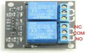
Fig. 6- 2 CHANNEL RELAY MODULE
Generally, a relay module has three teminals to connect the load. The three terminals are NO(Normally open), NC(Normally closed) and COM.The 2 channel relay board is entirely similar to relay module except that it has two relays on a single board to switch two different loads.
PIN DEFINITION
COM : Common pin
NC : Normally closed, in which case NC is connected to COM when INT1 is set low and disconnected
when INT1 is high.
NO : Normally open, in which case NO is disconnected with COM1 when INT1 is set low and connected
when INT1 is high.
FEATURES
Number of Relays : 2 Contact action time : 10ms/5ms
Rated load : 7A/240V AC, 10A/125V AC, 10A/28VDC
Control signal : TTL level
E. THINGSPEAK
ISSN (Print) : 2320 – 3765 ISSN (Online): 2278 – 8875
I
nternational
J
ournal of
A
dvanced
R
esearch in
E
lectrical,
E
lectronics and
I
nstrumentation
E
ngineering
(A High Impact Factor, Monthly, Peer Reviewed Journal) Website: www.ijareeie.com
Vol. 7, Issue 2, February 2018
Fig.7 THINGSPEAK CHANNEL FOR ANALYSIS
KEY CAPABILITIES OF THINGSPEAK
Configure devices to send data to Thingspeak using a REST API or MQTT.
Get instant visualizations of live or historical sensor data.
Run your IoT analytics automatically based on schedules or events.
Aggregate data on–demand from devices and third–party sources.
Pre-process and analyze your collected data using integrated MATLAB.
Act on your data and communicate using third-party services like Twilio or Twitter.
VIII. RESULT AND DISCUSSION
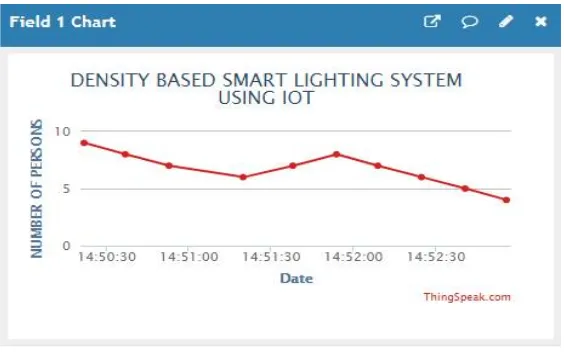
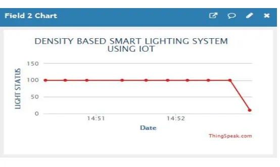
We have already created a channel on open source ThingSpeak website(www.thingspeak.com) where the data gets updated frequently. For every 15 to 20 seconds, the data is updated on ThingSpeak app. We have programmed in such a way that the light is turned ON, when the count reaches 5.If the light is in OFF state, the value is 10 whereas when it is in ON state, it indicates the value as 100.
Fig 8A NUMBER OF PERSONS Vs TIME
ISSN (Print) : 2320 – 3765 ISSN (Online): 2278 – 8875
I
nternational
J
ournal of
A
dvanced
R
esearch in
E
lectrical,
E
lectronics and
I
nstrumentation
E
ngineering
(A High Impact Factor, Monthly, Peer Reviewed Journal) Website: www.ijareeie.com
Vol. 7, Issue 2, February 2018
Fig 8B LIGHT_STATUS Vs TIME
In fig 8B, time lies along x-axis and light status lies along y-axis. .Similarly when the count reaches 4 which is below 5, the light is turned OFF and indicates the value as 10.
IX. CONCLUSION
Nowadays due to the population rise, electricity bill’s rates are also increasing very highly. In order to overcome the problem, we are going to implement our project in large gatherings.Upto now,the same lighting concept was limited to individual person’s entry. But in our project,we have used the concept of turning ON the system based on particular number of people entering into the room. It also stores the sensor parameters in the cloud in a timely manner. This will help the user to analyze the condition of various parameters of the particular place from anytime anywhere. It can be implemented for future purpose in large scale.
REFERENCES
[1]. Soyoung Hwang and Donghui Yu, “Remote Monitoring and Controlling System Based on Zigbee Networks” International Journal of Software Engineering and Its Applications Vol.6, No.3, July 2012.
[2]. Richu Sam Alex, R NarcissStarbell “Energy efficient Intelligent Street Lighting System using Zigbee and Sensors”, International Journal of Engineering and Advanced Technology(IJWAT), vol-3, Issue 4.april 2014.
[3]. Daeho Kim and Jaesang Cha, “Smart LED lighting system implementation using Human tracking US/IR sensor 2011 IEEE(ICTC 2011). [4]. Raja R, Dr.K.Udhayakumar “Development in Smart Sensor Network for Energy Saving” International Journal of advanced Research in Electrical, Electronics and Instrumentation Engineering (An ISO 3297:007 Certified Organization) Vol. 3, Special Issue 2,April 2014.
[5].B.K.Subramanyam, K Bhaskar Reddy, “Design and development of intelligent wireless Street light control and monitoring system along with GUI”, International Journal of Engineering Research and Applications(IJERA) Vol.3, Issue 4, Jul-Aug 2013.
[6]. Michale Mango, Tommaso Poloneli, Luca benini “A low Cost, Highly Scalable wireless Sensor Network solution to Achieve Smart LED Light Control for Green Buildings” IEEE sensors Journal VOL. 15, NO.5, MAY 2015.