ISSN (Print) : 2320 – 3765 ISSN (Online): 2278 – 8875
I
nternational
J
ournal of
A
dvanced
R
esearch in
E
lectrical,
E
lectronics and
I
nstrumentation
E
ngineering
(An ISO 3297: 2007 Certified Organization)
Website: www.ijareeie.com
Vol. 6, Issue 11, November 2017
The Broadbanding Properties of Multiresonant
E Shaped Patch Antenna
Pratap Singh Thakur
Lecturer, Department of ETE, V.M.Govt. Polytechnic College, Narsinghpur, Madhya Pradesh, India
ABSTRACT: The idea of punching slots on patch antenna to achieve multi-resonant and further broadband characteristics has been intelligent techniques. One such geometry is E shaped antenna in which two parallel slots are tweaked out at one side symmetrically to form an E shaped antenna, which is adopted in this paper to study its broadband characteristics. Besides geometrical variations, two other techniques like increasing the substrate height and decreasing the dielectric constant of the substrate are also incorporated with a limitation for fabrication ease. The resultant antenna has shown broad band characteristics of nearly 3.71 GHz.
KEYWORDS: Broadbanding, patch antenna, E shaped, slot antenna.
I. INTRODUCTION
A patch antenna is simple in structure occupies low volume and conformal to the region of installation there by leading to miniaturization of the electronic gadget in which it has to be embedded. The patch can also be fabricated with ease of bulk fabrication as well as with low cost. Besides these the patch antennas have a disadvantage of narrow bandwidth which constraints the operation to few applications. In general some communication systems demand for operation at multiple frequencies which are closely spaced. In such cases utilization of multiple antennas for multiple frequencies of operation would make the communication system more bulky. In such cases a single antenna with wide band characteristics covering all the bands of frequencies would be helpful. As discussed a patch antenna by basic nature narrow banded. Hence exploring several broadbanding techniques have become good part of research in antennas.
In this paper an E shaped microstrip patch antenna is used to obtain a wide bandwidth characteristics. The antenna is designed and simulated in High Frequency Structure Simulation (HFSS) Tool which has the capability of solving the electromagnetic structures using Finite Element Method. The designed antenna is solved and various reports like reflection coefficient, VSWR, Radiation Pattern and Directivity are taken.
II. BROADBANDING AND THEIR LIMITATIONS
The bandwidth of patch antenna can be increased by the height of the substrate or by decreasing the value of the dielectric constant of substrate.
Bandwidth of patches can be given by the expression-
BW= s-1/Q*s^(1\2)
For s=2, & substituting for Q in terms of energy stored & power radiated we can write BW=√2hGe/πc √ εrεo be………. (a)
Where Ge is the edge conductance, be is the effective width, h is the substrate thickness εr is the effective dielectric
constant.
Based on the above characteristic equations we can deduce the following points.
1- Decreasing the Q factor of patch by increasing substrate height & decreasing the dielectric constant. 2- Use the multiple resonator located in one plane.
3- Electromagnetically coupled patch Antenna.
ISSN (Print) : 2320 – 3765 ISSN (Online): 2278 – 8875
I
nternational
J
ournal of
A
dvanced
R
esearch in
E
lectrical,
E
lectronics and
I
nstrumentation
E
ngineering
(An ISO 3297: 2007 Certified Organization)
Website: www.ijareeie.com
Vol. 6, Issue 11, November 2017
The bandwidth of the micro strip patch antenna is limited because the operating bandwidth of a single linearly polarized patch antenna is limited by its input VSWR (Standing Wave Ratio) and it is inversely proportional to the Q factor of the patch resonator. In addition to the above techniques there are some limitations with the same which are listed as follows:
1-For probe fed patch antenna an increase in the thickness of substrate causes an increase in probe inductance which in turn creates input matching problems.
2-For micro strip fed patches, increased substrate thickness causes an increase junction reactance, which creates spurious radiation as well as input match problem.
3-Thick substrates make it mechanically difficult to have antenna arrays conformal to curved surfaces (of aircraft, space craft, missile etc.).
4-Many of the analysis and design techniques (cavity model etc.) become inaccurate for thick substrate.
Design with an E-Shaped Patch
By using an E-shaped patch, similar broadband operation can be obtained. The E-shaped patch is formed by inserting a pair of wide slits at the boundary of a microstrip patch.
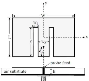
Figure 1. Geometry of a broadband E-shaped microstrip antenna
Non conducting posts of height h (not shown in the figure) from the ground plane. The two wide slits have the same length l and the same width w1 and are inserted at the bottom edge of the patch. The separation of the two wide slits is w2 and the two
slits are placed symmetrically with respect to the patch’s center line (y axis). There are thus only three parameters (l, w1, w2) for
the wide slits used here. Along the patch’s center line, a probe feed at a distance dp from the patch’s bottom edge can be located
for good excitation of the proposed antenna over a wide bandwidth.
III. DESIGN AND SIMULATION
ISSN (Print) : 2320 – 3765 ISSN (Online): 2278 – 8875
I
nternational
J
ournal of
A
dvanced
R
esearch in
E
lectrical,
E
lectronics and
I
nstrumentation
E
ngineering
(An ISO 3297: 2007 Certified Organization)
Website: www.ijareeie.com
Vol. 6, Issue 11, November 2017
Figure 2. Simulated E shaped antenna.
IV. RESULTS AND DISCUSSION
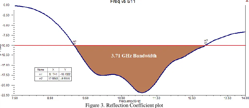
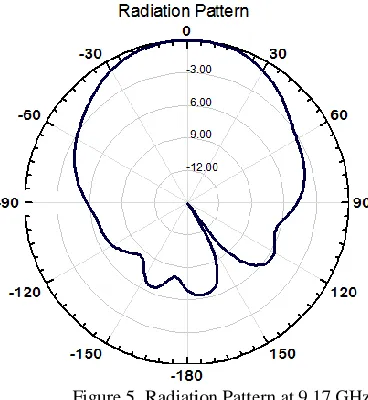
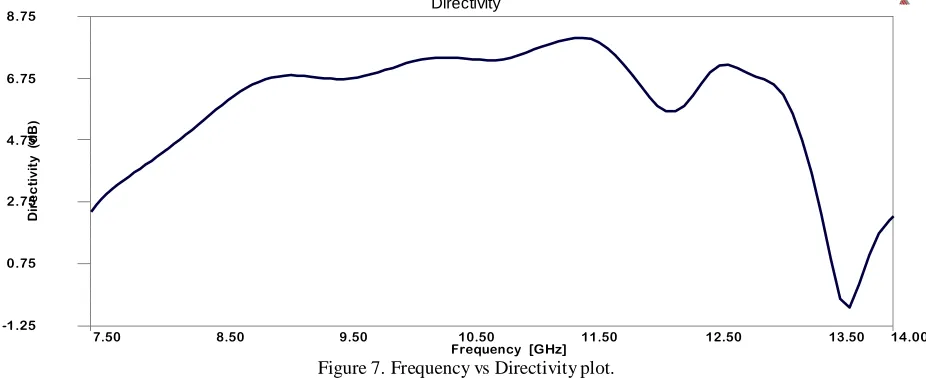
Basing on the geometry shown the Fig.2 and the solution setup and environment discussed in the previous section various reports are generated. The reflection Coefficient plot is as shown in the Fig.3. The corresponding VSWR is as shown in the Fig.4. The radiation pattern at the two edge frequencies of the bandwidth are presented in the Fig.5 and Fig.6. The frequency vs directivity is as shown in the Fig.7.
Figure 3. Reflection Coefficient plot
ISSN (Print) : 2320 – 3765 ISSN (Online): 2278 – 8875
I
nternational
J
ournal of
A
dvanced
R
esearch in
E
lectrical,
E
lectronics and
I
nstrumentation
E
ngineering
(An ISO 3297: 2007 Certified Organization)
Website: www.ijareeie.com
Vol. 6, Issue 11, November 2017
Figure 4. VSWR plot
From the VSWR plot shown in Fig.4 it can be seen that the value of VSWR is below 2 in the same frequency range obtained in Fig.3. Therefore this range of frequencies is concluded to be the bandwidth of the antenna.
Figure 5. Radiation Pattern at 9.17 GHz
ISSN (Print) : 2320 – 3765 ISSN (Online): 2278 – 8875
I
nternational
J
ournal of
A
dvanced
R
esearch in
E
lectrical,
E
lectronics and
I
nstrumentation
E
ngineering
(An ISO 3297: 2007 Certified Organization)
Website: www.ijareeie.com
Vol. 6, Issue 11, November 2017
D
ir
ec
ti
vi
ty
(
d
B
)
Figure 6. Radiation Pattern at 12.88 GHz
Also the directivity plot in Fig.7 shows a respectable value of D above 6dB for the bandwidth.
8.75 Directivity
6.75
4.75
2.75
0.75
-1.25
7.50 8.50 9.50 10.50 11.50 12.50 13.50 14.00 Frequency [GHz]
Figure 7. Frequency vs Directivity plot.
V.CONCLUSION
ISSN (Print) : 2320 – 3765 ISSN (Online): 2278 – 8875
I
nternational
J
ournal of
A
dvanced
R
esearch in
E
lectrical,
E
lectronics and
I
nstrumentation
E
ngineering
(An ISO 3297: 2007 Certified Organization)
Website: www.ijareeie.com
Vol. 6, Issue 11, November 2017
REFERENCES
[1] R. Garg, P. Bhartia, I. Bahl, and A. Ittipiboon, Microstrip Antenna Design Handbook, ArtechHouse, 2001.
[2] D. R. Jackson, S. A. Long, J. T. Williams, and V. B. Davis,“Computer- aided design of rectangular microstrip antenna s”. [3] D. M. Pozar,“A reciprocity method of analysis for printed slot and slot- coupled microstrip antennas”
[4] H. Pues and A Van de Capelle,“Accurate transmi ssion-line model for the rectangular microstrip antenna”. [5] W. F. Richards, Y. T. Lo, and D. D. Harrison,“An improved theory of microstrip antennas with applications”.
[6] K.M Luk, C.L.Mak, Y.L Chow, K.F Lee, “Broadband Microstrip Patch Antenna” Vol. 34, Issue 15, Electronic Letters, July 1998.
[7] B. L. Ooi and Q. Shen “A novel E-shaped broadband microstrip patch antenna” Microwave and Optical Technology Letters, Vol. 27, Issue 6, Dec 2000. [8] Ge, Y. Esselle, K.P. ; Bird, T.S. “Broadband E-shaped patch antennas for 5-6 GHz wireless computer net works” Vol. 2, Antenna and
Propagation Society International Symposium, June 2003
[9] A.A. Deshmukh and G. Kumar “Compact Broadband E sha ped microstrip antenna”, Electronic Letters, Vol.41, Issue 18, Sep. 2005. [10] Yuehe Ge, Karu P Esselle and Trevor S Bird “A Broadband E-shaped patch antenna compatible with microstrip feed” Microwave and Optical