_ _ _ "J/ I
--ib
-
--
-~---...I , ---I - - - ' ,-__ ....J' -__
-.J,
,
~...
-....
-~
---...J ----...J----...J ----...J - - - - I - - - - . . . J
- J ----...J - J ----...J - J ----...J
- J ----...J
- J ---'
---'
- - - ' - - - '
- - J - - J - - J - - J - - J - - J
~
-- -- J '
- - '
IBM
3420/3803
Magnetic Tape Subsystem
- - - ' /
_ _ _ ...J/ _ _ _ ...J/
_ _ _ -.J/
-...
---' ---' ---' ---' ---' - J - J-
--, ----I-
-- J - J ,--- ---
-~-
-
-
--
~~
-- -- J
~ ~
~ ~
~~
- - J ~
--
--
---
--
--
--Reference Guide
_ _ _ _ _ ,- - - . J
/
_ _ _ J/
---,~
~
I
I I
--(
(:
(~~'
c~
<-~.
(
3420/3803 REFERENCE GUIDE
PREFACE:
This reference guide was created by FE Service Planning to assist in
maintaining the 3420/3803 magnetic tape subsystem. It is divided into
sections for each major topic. Reference is made to the 3420/3803 MLM, and other publications that are required for effective 3420/3803 maintenance.
This guide is not eligible for suggestion awards unless a tangible savings can be shown.
Address any comments concerning this publication to:
Preface
International Business Machines Corporation Field Engineering Service Planning
Department 96F, Building 005 Tucson, Arizona 85744
(""
(-(
f
f··
f
:(
f
f
:{
f
(
(
(
(~
(::
(-;
C'
('
3420/3803 REFERENCE GUIDE
SECTION
3420/3803 Tape Subsystem Maintenance Directory ... 1
3420/3803 General ... 2
MLM Content ... 3
EREP
&
Predictive Maintenance ... 43420 Read/Write Service Techniques ... 5
3420 Tape Motion Service Techniques ... 6
3420 Performance Enhancement Guide ... 7
3420 Quick Fix MAPS ... 8
Sense Byte Analysis ... 9
Media And Related Problems ... 10
3420/3803 Online Tests ... 11
3420/3803 Power Hints ... 12
Common System Abends ... 13
3420 Parts ... 14
Tools & Test ... 15
3803 Data Flow ... 16
3803 Mi cro Processor Ti ps ... 17
3803 Channel Interface ... 18
3420 ECA Listing ... 19
3803 ECA Listing ... 20
Index ... 21
\
"-;
(-(
(
c
(
"j
c
c
c
..
'~ "
3420/3803 REFERENCE GUIDE
ENTRY 3420/3803 TAPE SUBSYSTEM MAINTENANCE DIRECTORY
FOR EACH DECISION, A LIST OF AVAILABLE MAINTENANCE DOCUMENTATION OR MAINTENANCE PROCEDURES IS PROVIDED
- REFERENCE GUIDE SECTION 8
~ MLM START PAGES -,MLM QUICK FIX 00-007 - MLM FIELD FEEDBACK
00-050
- REFERENCE GUIDE SECTION -3 - MLM INDEX VOL 4
- REFERENCE GUIDE SECTION 11 - OLT USER GUIDE
FORM #D99-3420A
- REFERENCE GUIDE SECTION 4 -EREPSRL
I
FORM # GC28-0772- REFERENCE GUIDE SECTION 14 - MST CARDS LOGIC
PAGE MOOl
- CONTROL BOARDS ASSOCIATED LOGIC - PARTS CATALOGS
3420 M3,5,7 S132-0005 M4,6,8 S132-0007 3803 M1,2 s132-0004
- REFERENCE GUIDE SECTION 19-20 - MICROFICHE - RETAIN TIPS
MLM 85-000
- REFERENCE GUIDE SECTION 14
- MAINTENANCE LIBRARY FORM #S131-0037
- 'REFERENCE GUIDE SECTION 13,
- SUBSYSTEM DESCRIPTION FORM #GA32-0021
- REFERENCE GUIDE-SECTION 10
- REFERENCE GUIDE SECTION 7
(
{
(
c
(
(
(
(
""J
~'.
3420/3803 REFERENCE GUIDE
3803/3420 MST BOARD ORDERING
The following information must be supplied when ordering a 3803/3420
MST board for field replacement.
o Machine type and serial number o Part number of the MST board o EC level of the board
o REAs installed (if any)
o Board location (example - B3)
o Name and phone number of person to contact in case the plant needs further information
Refer to AA005 (3803) or A6106 (3420) in the logics for feature wiring before installing the board. 3803 MST boards may require installation of tie upldown resistors.See part numbers below.
3803 TIE UPIDOWN RESISTORS:
PIN Type - - - - -Wi re Color Resistance - - - -Tie to Pin
2520936 Tie-Up Blue 51 ohm GND (D08, J08,
or U08)
2520942 Tie-Down Yellow 620 ohm -4V (B06, G06,
or S06)
3803 A2 AND B2 BOARD PART NUMBERS
For 3803 Models 1 and 2, board A2 is PIN 2521394. (Note: Board A2 might have factory PIN 1394001 or PIN 1394002 on the label, but these boards cannot be ordered. Use PIN 2521394) The B2 board in
P08,
M06,
the 3803 Models 1 and 2 at EC level 733814 can be P/N1384001, 1384002 or 2521384. Without EC 733814, the correct part of the B2 board is PIN 2521392. Refer to logic page AA005 for wiring that must be added.
3803 MST BOARD REPLACEMENT
The 3803 MST boards contain back panel jumpers that customize the board to the machine in which it is used. The jumper locations are identified on logic page AA005. Boards are shipped without jumpers on them, and problems occur if a board is replaced and the jumpers are not added to the new board.
3803 MST FLAT CABLE REPLACEMENT
To order a temporary repair cable, use the following procedure:
1. Obtain "Cable Assembly PIN" from the label on the "To" end (Note: Cables manufactured prior to September 1, 1965 will have all seven digits of the PIN. Cables manufactured after September 1, 1965 have only the last 4 digits. The
number "58011 can be assumed to be the first three high
order digits in all cases). 2. Determine length by:
o Actual length given on IITO II cable label or o Physicl measurement of actual cable.
(manufactured before to Sept. 1, 1965)
3. Ascertain whether the cable being replaced is polyethylene or Teflon covered. Polyethylene is milk-white, Teflon is clear.
4. Select the correct temporary repair cable from General CEM 251 that is nearest to the length required.
5. Order the temporary repair cable PIN (obtained from the right hand column in general CEM 251)
LABEL IDENTIFICATION
The following figures describe the information contained on the labels.
Frame Board Socket
Gate Pos. Pos.
\ \ I
i
=oL~
____
i
IITII i ndi cates IITolI--+I-T X X X X X X X X T
1 1
Socket Pos.
B=Bottom - T= Top
1 ~---+t---cable length in inches
Cable Assembly PIN
I
~
i
(Last 4 digits ~ X X X X X X X X+I---Strain Relief Code
ceeded by 580) 1 1
1 1
1 ____ _____I
Sequence Number
--+1-
X X X X X X X X X + I - - - Card Assembly PIN1 1 Last 5 digits
1 __ __ ____ --",-I
~X X
f
X X \ X X X X+-i---JOb No.ECA~
Code /
=
i.st
'Qd~
\Qa~e Cod~
To label (Mfg. after September 1, 1965)
Note: The Test Code andlor Date Code may be missing on cables made between September 1, 1965 and September 18, 1968.
3420 General 2.2
(
(
(~
(
(
(
(
(
«
(
(-(
(
(-
(~--(~
3420/3803 REFERENCE GUIDE
3803 MST FLAT CABLE REPLACEMENT (CONT'D)
Socket Pos.
"F" Indicates B
=
Bottom - T=
TopCable list P/N*---+--X X X X X X X 0 XI Strain relief
~oswego
Mfg.~---41
code
Sequence Number*--+-X X X X X X X X X+-I---Card assembly PIN
I
EC number - - - + - E C X X X X X X X I I From label* This information is necessary for ordering new cables, and
it must be obtained from the label on the "From" end of the cable.
3420 4,6,8 LOGIC BOARD REPLACEMENT
When replacing logic board 01A, in 3420 Model 4, 6, and 8 tape drives, it is necessary to add wires to the board for model identification and speed. The chart that shows the correct wiring is on logic page A6106 in the 3420 logic manual. Difficult-to-analyze read and write problems will occur if these wires are not added to the board. Also refer to MLM page 08-630, 3420 logic panel removal/replacement.
3420 MST FLAT CABLES REPLACEMENT:
PIN 5802133 uses PIN 5802180 48 in. PIN 5802181 64 in. PIN 5802134 uses PIN 5802182 48 in. PIN 5802183 64 in.
3420/3803 REFERENCE GUIDE
3803 and 3420 CABLE REQUIREMENTS
A total cable length of 200 feet (unless modified by general control-to-channel cabling schematic) is available to attach up to eight control units, Cable lengths between a 3803 with a 3420 Model 6 or Model 8 attached (at 6,250 bpi) and the channel are shown below.
2860 2880
To
Block Multiplexer Channel/3800 Selector Channel
Max Length (ft) With 3420 Model 8 Attached
72 119 72*,103 72*,119
Max Length (ft) With 3420 Model 6 Attached
200 200 200 200
*On System/370 Model 135/138 and 4331 Processor Model Group 2
For each control unit connected between the 3803 and the channel, the cable length shown must be reduced by 15 feet if 3420 Model 6 is attached, or 20 feet if 3420 Model 8 is attached.
3420 General 2.4
if"',
U
(("\
l
(-(
(-(
r
f
(
(
(
(
(
3420/3803 REFERENCE GUIDE
3803-1/3420 MLM/PF DESCRIPTION AND ORGANIZATION
VOLUME I
3803-1/3420 Maintenance philosophy How to use the MAPS
Legend
&
symbols MAP formatsLine levels/standard voltages Status and sense bytes
Acronyms and abbreviations
CE initial entry
3803/3420 problem determination Permanent read error analysis Tape developing procedure End of call
Single tape unit problems
Mod 3,5,7 Power problem analysis
Mod 3,5,7 Drop ready, thread, load failures
Mod 3,5,7 Motion, rewind, capstan, reels
Mod 3,5,7 Unload problems
Mod 3,5,7 R/W problems, envelope failure, runaway
Mod 3,5,7 Capstan problems
Device interface lines
Intermittent drop ready problems
Checks, adjustments, removal and replacements
MLM Contents 3.1
SECTION
Plan 1 Plan 2 Plan 2 Plan 3 Plan 5 Plan 6 Plan 7
Start 1 00-010 00-011 00-014 00-030 00-040
1A-000
2A-000
3A-000
4A-000
5A-000
6A-OOO
07-000
07-010
3803-1/3420 MLM/PF DESCRIPTION AND ORGANIZATION
VOLUME II
OLTEP/OLTSEP problem determination Read error analysis
Velocity error analysis Unit check analysis Command reject analysis
Intervention required analysis Bus-out check analysis
Equipment check analysis
Command or control status reject analysis Data check analysis
TCU power supply failure analysis Reset problems
Offline duplication of online failures CE panel operational suggestions
Procedure for locating a failing command
Online/offline MP errors or hangs Offline test procedures
System-hangs
ROS loops on error stops
How to use sections 15, 16 and 17
Sense analysis
Picking/dropping records
ALU 2 microprogram errors
Write data checks Read data checks
Write data flow problem information and related MST cards
Read data flow problem information and related MST cards
Diagnostic programs Tape runaway
CU usage meter does not run
Tape unit will not respond to S10 Multiple tape unit access problems Tape switch support information Channel/CU interface problems
Olt section A command sequence chart 3803-1/3420 data flow block diagram Status and sense bytes
MLM Contents 3.2
{:
(
(
(-(
(~
(
(O~.',
-'
c
3420/3803 REFERENCE GUIDE
Field tester
Diagnostic techniques MST and cross-reference Exchangeable cards, 3803
Board layouts for the TCU and TU boards
Tools and test equipment Sense byte 7 or 10 extraction
Local storage register (LSR) display procedure
CE panel switch and indicator functions CE panel data security erase procedure
Service aids
Subsystem preventive maintenance
MLM Contents 3.3
19-004 19-008 19-009 19-023 19-026
20-000 20-005
21-001
22-000 22-005
23-000
3803-2/3420 MLM DESCRIPTION AND ORGANIZATION
VOLUME I
3803-2/3420 Maintenance philosophy Acronyms
Legend
&
symbols Glossary of terms OrganizationMLM tab placement by volume
CE initial entry How to use MAPS
Status and sense bytes
Sense bytes not defined in MAPS 3803-2 Subsystem quick fix index 3420/3803 symptom index
Permanent read/write error analysis Develop tape error examples
End of call Abends theory
Single tape unit problems Field feedback
Mod 3,5,7 Power problem analysis
Mos 3,5,7 Drop ready, thread road failures
Mod 3,5,7 Motion, rewind, capstan, reels
Mod 3,5,7 Unload problems
Mod 3,5,7 R/W problems, envelope failure, runaway
Mod 3,5,7 Capstan problems
Mod 4,6,8 Power problem analysis
Mod 4,6,8 Drop ready thread load failure
Mod 4,6,8 Motion and rewind failures
Mod 4,6,8 Unload failures
Mod 4,6,8 R/W failures, envelope failure, runaway
Mod 4,6,8 Tape motion, capstan failure
MLM Contents 3.4
SECTION
Plan 1 Plan 2 Plan 4 Plan 5 Plan 6 Plan 7
Start 1 00-000 00-005 00-007 00-009 00-010 00-014 00-016 00-030 00-035 00-040 00-050
1A-000
2A-000
3A-000
4A-000
5A-000
6A-000
18-000
28-000
38-000
48-000
58-000
68-000
(
«
r
(
(J'
(,
('
c
3420/3803 REFERENCE GUIDE
3803-2/3420 MLM DESCRIPTION AND ORGANIZATION
VOLUME II
Device interface lines Intermittent drop ready
Checks, adjustments, removals, and replacements
TCU power supply MAPs
Offline duplication of online failures Extracting sense data
3803 CE panel operation and data flow
MAP procedures for ALU hangs or loops, channel busy, timeout, or other indications where the microprogram does not appear to be looping normally (possibly also causing channel hang)
Manual analysis of sense data using a prioritized scheme
MAP procedures for miscellaneous errors
MLM Contents 3.5
SECTION
07-000 07-010
08-000
11-000
12-000 12-001 12-010
13-000
14-000
3803-2/3420 MLM DESCRIPTION AND ORGANIZATION
VOLUME III
Microprocessor diagnose, loop, and scoping procedure
A. Determine the failing instruction address B. Make ALU loop on an error
C. General reference information
Microprocessor card interchange list
A. Long and short instruction cycle timing chart
Sense bit MAP procedures for equipment checks
Sense bit MAP procedures for data checks, including timing charts of various data operations plus second levels of the conditions required to produce the error
1X8 selection logic MAP
Device switch theory and MAPs for problems isolated to the device switch.
Tape control channel interface problems
Extra or missing interrupt
Tape control metering problems
Board layouts for the TCU and TU boards showing the functions performed for each card to assist in card swapping.
Logic net cross-reference list. The MAP scoping procedures allow you to identify a failing line and the FRU from which this line originates. If replacing that FRU does not correct the problem, you may suspect a loading problem at the other end of the line (net). This cross-reference list provides the references to logic for all line (net) names encountered in the MAPs so that you may more easily pursue problems of this
nature.
OLTEP error message analysis. Used as directed by sense analysis sections 3420RO and WR after certain errors encountered by sections 3420 F
,d G.
tents 3.6
SECTION
16-000
16-001
16-010
17-010
18-000
18-010
18-040
18-050
18-060
19-000
20-000
21-000
,r"",
, \ ,
"'-"
',... ,
r ' ,
i/
"
( \
" , 7
""-'-',
7/
/---...
''-.,/
/~,
('-'"
\ '-<../
«
(
(
(.
(
"
(
...3420/3803 REFERENCE GUIDE
3803-2/3420 MLM DESCRIPTION ORGANIZATION
VOLUME IV
Subsystem characteristics, features, etc.
Control unit data flow Channel Tag in/Bus in regs
Microprocessor information and instructions
Specific circuits, oscillator through read cycle controls
Device interface, command types, channel priority
Loop write to read, recording technique, and common MP routines
NRZI, translate, data convert
Two-channel switch (MIS) and device switch theory (TCS) 2x8, 3x8, etc.
CE panel-description of switches and indicators
Tools and Test Equipment list
PM procedures and schedules
Subsystem installation procedures
Field tester conversion
Index (detailed index volumes 1 through 4)
MLM Contents 3.7
SECTION
40-000
50-000 52-040
53-005
54-000
55-005
57-006
58-005
75-001
80-000
85-000
90-000
90-170
"f
c
[
(
(~
C'-"
'-'~
(
3420/3803 REFERENCE GUIDE
EREP AND PREDICTIVE MAINTENANCE
Predictive maintenance is the process of detecting a trend of reduced system or product performance, and fixing the problems to restore proper performance.
Predictive maintenance has been proven to reduce repair actions (RA), CE hours, and maintenance parts costs, as well as to maintain a high level of customer satisfaction.
EREP is the tool used to observe the level of performance. A series of re-ports entitled; the Tape Subsystem Exception Rere-ports, will be used to assist with the predictive maintenance. These reports are generated by EREP 1.3 that
has the customer ordered enhancements installed (refer to announcement letter #282-215, dated 15 OCTOBER 1982).
The following pages describe the Subsystem Exception Reports and how they can be used to do predictive maintenance.
SUBSYSTEM EXCEPTION REPORTS THAT ARE AVAILABLE FOR TAPE
o Subsystem Exception Tape - 5 exception categories.
o Tape Permanent Error Summary - Sense bytes, explanation and
other data for each failure.
o Tape Temporary Error Summary - Total temporary errors for
each subsystem device.
o Tape CUA Statistics Summary for -CUA - A report for each CUA that was
an exception. Shows statistics of each demount.
o Tape Volume Statistics Summary - Statistics for each exception
volume mount are listed.
4.3
4.15
4.16
4.19
4.21
The detailed content of these reports is explained on the following pages. Much of this material has been taken from; ENVIRONMENTAL RECORDING EDITING AND PRINTING (EREP) PROGRAM, GC28-0772-6, as revised 1 September 1982.
m ; 0 m ""0 .po. N
SUBSYSTEI1 EXCEPTioN TAPE
D
REPORT DATE 174 82
PERIOD FROH 170 82
TO 171 12
--- 3420 ---1600 IPI 6250 IPI --- 3410 ---1600 BPI
TEHP URT(CT) TEMP RD(CT) TEMP URT(CT) TEI1P RDCCT) TEHP URT(CTJ TEMP RDCCT)
D CURRENT LIMITS
HBYTES'ERR(CT) HARDUARE VOLUI1E
4 CIS) 26 ( 2) 4 (IS) 26 ( 2)
4 CIS) 26 ( 2) It (IS) 26 ( 2)
DO
IIII
EXCEPTION VOLUI1E SERIAL ADDR
a
C 0
P EQU
UCHK READ(CT) . URITE(CT) ----HI/ERR PERH---- II URITE(CT) ---I1I/ERR TEI1P---READ(CT) BUS OVR OUT RUN SIDCOUHT HARDUARE
PERHAUENT· ERROR
HI.RD~ARE
9B8 A 2
37E A 0
37D A 0
-- ( 0) 2U 1)
- - ( 0)
FAILED TEHFORARY READ OR URITE LIHITS
3C2 A 0 - - ( 0)
VOLUI1E OR CREATING DRIVE
-- ( 0) 164( 7)
- - ( 0) ( 0)
482( 1) - - ( 0)
- - ( 0) O( 27)
PElllIl.tlENT READ DR lJllITE ERRORS OR RESET KEY ON HaRE THAH ONE DRIVE
079699 992 A 0 O( 2)
--
( 0)--
( 0) VOLU~E OR CRE~TING DRIVEFAILED TEHPCRARY READ OR ~RITE LIHITS OH HORE THAN OHE DRIVE
050971 9Bl A 0
--
( 0)--
( 0) O( 10) VOLUI1~FAILED TEI1PORARY READ OR URITE LIHITS
051007 3C2 A 0 - - . ( 0) 0) O( 11
( 0) o 0
( 0) o 0
( 0) o 0
- - ( 0) o 0
--
( 0) 0 0a( 4) 0 0
O( 4) 0 0
TOTAL NUHBER OF DRIVES OH REPORT ,. ( 12%) TOTAL NU~IER OFVOLUI1ES USED = ImT ON REPORT 30 ( 88%J III TOTAL HUHBER OF VOLUMES LISTED =
178K 61K 14K lK 90 4K 37 457 3
(ll) AN AVER ACE BLOCK LENGTH UAS USED IECAUSE A ZERD ILOCK LENGTH UAS FOUND IN ONE OR HORE OBR RECORDS
AVERAGE BLOCK LENGTH = 10742
CPU A 8 HODEL lOll JOl3
SERIAL NUHBER
707070 III a08080
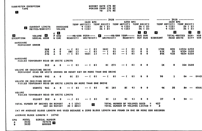
Figure 4.1 Tape Subsystem Exception Report
~~ .",
\ '
(
It (15) 26 ( 2) 4 (15) 26 ( 2)
lID ID
TOTAL-HBYTES READ URITE DEN-SITY
820 1154. 6250
28 612. 1600 UI 482. 6250
o 16* 1600
1 Oll
3S a.
--0 o.
[image:21.796.63.734.67.503.2]--.po. N C) ... w 00 C) w ; 0 m -n m ; 0
IS m z:
HDR n
SER m
G)
c
I - t
-("'
. '-~ (~
("
f
('
(
(
[
(
(~~
("
3420/3803 REFERENCE GUIDE
TAPE SUBSYSTEM EXCEPTION REPORT
This report indicates if the tape subsystem has permanent errors, or is oper-ating within acceptable limits. You specify LIMIT controls for both hardware and volume to prevent the printing of excessive temporary errors. See IILIMIT Control Statementll on page 4.23 When you do not specify limits for temporary errors, only pe~manent errors appear on the exception report.
NOTES: (The item numbers below refer to the block numbers in fig. 4.1)
1. **WARNING**: A message appears here if the input records span more than 3 days. The problem causing the error might already have been fixed.
2. CURRENT LIMITS. These two lines show the limits set in the LIMIT control statements included when the report was requested. The limits are set for temporary read and write errors occurring in the HARDWARE (device) and on the VOLUME. They prevent the printing of all temporary errors except those that occurred at the specified frequency level.
EREP
In the tape reports, the current limits are grouped under device type (3420 and 3410), tape density (1600 BPI and 6250 BPI), and TEMP WRT and TEMP RD. They show the specified number of megabytes read or written per error (MBYTES/ERR) and the specified total number of errors recorded (CT). In the example report (figure 4.1), temporary write errors re-corded against a 3420 drive (hardware) at a density of either 1600 or 6250 BPI will not appear as exceptions unless there are at least 15 er-rors occurring at a rate of 1 or more erer-rors in each 4 megabytes of data written. Temporary read errors on a 3420 at either density will qualify as exceptions if there are 2 or more errors occurring at a rate of 1 or more errors in each 26 megabytes of data read.
~j
3420/3803 REFERENCE GUIDE
c
3.
EREP
EXCEPTION. Errors are in thi s report by exception type; the type of exception serves as an indicator of the suspected source of the problem. The Subsystem Exception Tape report consists of 5 major headings, with exception categories. They are:
o Hardware
Permanent Error 4.6
o Hardware
Failed Temporary Read or Write Limits 4.7
o Volume or Creating Drive
Permanent Read or Write Errors or Reset Key on More Than One Drive
o Volume or Creating Drive
Failed Temporary Read or Write Limits
4.9
on More Than One Drive 4.12
o Volume
Failed Temporary Read or Write Limits 4.14
C)
Each exception indicated under the above headings, must be investigated \~J
to insure satisfactory performance of the tape subsystem. The
de-scriptions contained in this guide, will help you understand the meaning .- ~
of the exceptions. In addition, a technique for analyzing each exception report category is provided.
If this Subsystem Exception Report indicates that corrective action is necessary, the four tape reports that follow, (Tape Permanent Error Sum-mary, Tape Temporary Error SumSum-mary, Tape CUA Statistics Summary for -CUA,
and Tape Volume Statistics Summary) are used to provide additional infor- ,.'
mation to assist with the analysis of each exception example.
4.4
rt'
~-,j
(
(
(~
(
(
(
(
(
[
(
(
(
(
3420/3803 REFERENCE GUIDE
4. ADDR. This column contains the CUAs (channel/unit addresses) against which the permanent and temporary errors were recorded.
5. EQU CHK. Count of equipment checks.
6. MB/ERR PERM and MB/ERR TEMP. These columns 1 i st the actual num-bers of errors recorded during the report period, and the actual error rate, for this CUA. In the example, CUA 37E recorded 1 permanent read error in 28 megabytes of data read: CUA 9B8 recorded a total of 7 tempo-rary write errors in 164 megabytes of data written.
7. BUS OUT. The bus out check count from the statistical data recorded (SDR) counters.
8. OVR RUN. The overrun count from the SDR counters.
9. SIOCOUNT. The number of START I/O instructions issued against this CUA during the report period, in thousands.
10. TOTAL MBYTES READ WRITE. The total number of megabytes read or written during the report period.
11. DENSITY. The tape density, from the mode byte in the OBR record. 12. HDR SER. The serial number of the creating drive, from the tape
header.
13. Number of drives (hardware) and volumes appearing on this report, in com-parison to the total drives and volumes.
14. This area identifies the model and serial number of the CPU(s) which have been designated elsewhere in this report by a letter.
TAPE SUBSYSTEM EXCEPTION REPORT ANALYSIS
The following pages describe a technique for performing the analysis of the Tape Subsystem Exception Report. Each heading will be described separately.
EXCEPTION HARDWARE
Permanent Error
The CUAs listed have encountered at least one permanent error during the re-porting period. The temporary performance is also indicated for each failing CUA. Additional details about the permanent errors are contained in the re-port entitled) Tape Permanent Error Summary.
For an explanation of the details contained in the "Tape Permanent Error Sum-ma ry" report) see page 4.15.
EREP
ERROR ANALYSIS
o Note the type of permanent error.
Is it an equipment check) read) or write?
o Refer to the "Tape Permanent Error Summary" report and note the explanation of the error.
o Use the 3803/3420 MLM index (volume 4) or sense byte chart (MLM OO-OOS»)to locate the
associated map.
o CAUTION: A PROBLEM THAT IS REPORTED AS A SINGLE 3420 FAILURE, DOES NOT USUALLY INDICATE THE NEED TO REPLACE ANY OF THE 3803 FRUs.
o Do 3420 checks and/or adjustments as suggested.
o The following aids are available further analysis:
Field Feedback Quick Fix Sense Analysis Sense Byte Chart Symptom Index
4.6
for help in
MLM-OO-OSO MLM-00-009 MLM-14-000 MLM-OO-OOS MLM-OO-OlO
.f ...
I _ " j /
\ .... /
If'"
I",,"j
(
f
(
(
t
(
(
3420/3803 REFERENCE GUIDE
EXCEPTION HARDWARE
Failed Temporary Read or Write Limits
The CUAs listed have temporary errors exceeding the current limits (Note 1). The EREP program has determined that the listed drives did not perform to the current limits with various tape volumes mounted.
Note 1:
The temporary read, write limits used to determine the exceptions in this cat-egory, are coded by the CE using the LIMIT control statements. Refer to page 4.23 for details.
ERROR ANALYSIS
Refer to the flowchart on page 4.8 and follow the directions.
3420/3803 REFERENCE GUIDE
ANALYSIS OF HARDWARE FAILED TEMPORARY READ OR WRITE LIMITS
NOT CONCLUSIVE
REFER TO PERFORMANCE ENHANCEMENT GUIDE SECTION 7
EREP
REFER TO TAPE TEMPORARY ERROR SUMMARY REPORT EXAMPLE P 4.16
REFER TO THE TAPE CUA STATISTIC REPORT FOR FOR THE FAILING DRIVE EXAMPLE P 4.19
PAGE TO DETEHNINE IF ·THE ERHORS ARE DUE TO
1"1''"'
0, "",m,.: RD/WRT
REFEI{ TO RD/WRT SERVICE TECHNIQUES SECTION 5
YES
NO
MOTION
4.8
CHART 1
RD/WRT
EWV/VRC MTE/LRC
EDC/CRC
SKEW ERR R/W VRC WTM CHK
I • FER TO MOTION SERVICE
ECl!NIQUES SECTION 6
MOTION
SRC/PC VEL CHG
PAR/TACH
DRIVE IS FAILING ON WRITE OPERATIONS. REFER TO 3420 RD/WRT SERVICE TECHNIQUES SECTION 5
REFER TO TAPE VOL STATISTICS REPORT
(EX 4 • 21) FOR VOLUMES WITH HIGH ERROR COUNT. VOLUMES COULD BE WRITTEN BAD. TRACK VOLUMES IN FUTURE REPORTS
i,;tj
~. ~ ... /
(
(
(
{
[
(
c-(
(-(~
(,
3420/3803 REFERENCE GUIDE
EXCEPTION
VOLUME OR CREATING DRIVE
Permanent Read or Write Errors or Reset Key on More Than One Drive
All tape volumes listed, failed with a permanent error on more than one drive. Additional details about the permanent are contained in the reports entitled, Tape Permanent Error Summary and Tape Volume Statistics Summary.
For an explanation of the details contained in the IITape Permanent Error Sum-maryll report, see page 4.15; and for the IITape Volume Statistics SumSum-maryll re-port, see page 4.21.
ERROR ANALYSIS
Permanent Read errors indicate that the volume was created in error or that the tape was damaged after creation.
Permanent Write errors usually indicate that it is not possible to write the 6250 load point format SAGe or 10 burst. This is caused by damaged tape in the load point. Damage anywhere else on the tape would indicate that damage was across 15 erase gap areas, which is approximately 50 inches of tape. This is caused by the way the IOCS Tape Error Handler forces a backspace, erase gap, and rewrite sequence 15 times, before a permanent write error is recorded.
Refer to the flowchart on page 4.10 and follow the directions.
3420/3803 REFERENCE GUIDE
VOLUME OR CREATING DRIVE PERMANENT READ, WRI'IE OR RESET KEY ON MORE THAN ONE DRIVE
OTHER
~~ALYZE EXP~ATION
OF ERROR IN THE ASSOCIATED MLM MAP
~SE SENSE ANALYSIS SECTION 9
CHECK VOLUME FOR DAHAGE IN LOAD POINT AREA.
REFER TO SECTION, 10
EREP
REFER TO TAPE PERMANENT ERROR SUMMARY FOR DETAIL SENSE & EXPLANATION FOR THE VOLUME EXAMPLE PG 4. 15
I WRITE
LONG CREASE OR , EDGE DAl-lAGE.
REFER 'I'O SECTION 10
YES
READ
4.10
OPERATOR DEPRESSED THE RESET :KEY
BECAUSE TAPE RAN AWAY. THIS IS USUALLY DUE TO OPERATIONAL PROBLEMS. WRONG DENSI'I'Y. E;Rl\SED TAPE ETC. FAILURE CAN BE CAUSED BY AUTO CLEANE FAILING TO RETRACT.
THIS INDICATES THE TAPE WAS EITHER WRITTEN WITH THE ERROR OR HAS BEEN DAMAGED SINCE.
1. MOTION OR RD/WRT ERROR (CHART 1
PG 4.B
2. OBTAIN TAPE AND DEVELOP THE FAILURE REFER MLM 00-011
Nol
YES
DON'T KNOW
C
" ';
j\.., /
(
,''''
' \(
(
(
(~
(
(-(
(
3420/3803 REFERENCE GUIDE
VOLUME OR CREATING DRIVE PERMANENT READ, WRITE, OR RESET KEY ON MORE THAN ONE DRIVE
DON'T/KNow
REFER TO PERFORMANCE
ENHANCEMENTS
GUIDE SECTION 7
EREP
DETERMINE CREATING DRIVE FROM HDR SERIAL
REFER TO RD/WRT
SERVICE TECHNIQUE
SECTION 5
TAPE DAMAGE IN THE FAILING AREA COULD BE CAUSED BY ANY DRIVE IT HAS BEEN MOUNTED ON SINCE CREATION. RUN AN EREP THRESHOLD REPORT FOR THE VOLUME AGAINST THE HISTORY
TAPE. DETERMINE WHEN
THE TAFE WAS DAMAGED, AND THE DRIVE. REFER TO SECTION 10
4.11
MOTION
REFER TO MOTION
SERVICE TECHNIQUES
EXCEPTION
VOLUME OR CREATING DRIVE
Failed Temporary Read or Write Limits on More Than One Drive
Volumes listed did not perform to the current limits (Note 1) on more than one drive.
Note 1:
The temporary read, write limits used to determine the exceptions in this cat-egory, are coded by the CE using the LIMIT control statements. Refer to page 4.23 for details.
ERROR ANALYSIS
If the failures are temporary read errors, then the tape was either written in error by the creating drive or the tape was damaged in an operation that fol-lowed.
If the failures are temporary write errors, then the tape volume has excessive
c
/
j
damage. / ,
Refer to the flowchart on page 4.13 and follow the directions.
EREP 4.12
c
tr~·
I
(
(
(
(
L
(
(
(
(~
(
'"j
3420/3803 REFERENCE GUIDE
VOLUME OR CREATING DRIVE FAILED TEMPORARY READ OR WRITE LIMITS ON MORE THAN ONE DRIVE
EREP
REFER TO THE 'TAPE VOLUME STATISTICS' REPORT EX. PG 4. 21 ANALYZE DETAIL OF FAILURES FOR EACH MOUNT
DETERMINE CREATING DRIVE FROM HDR SN.
NO
VARIATION MAY BE DUE TO MARGINAL
CONDITION OF THE CREATING DRIVE. DETERMINE IF FAILURES IS NOTION OR RD/WRT
RELATED. TRACK VOLUME
AND CREATING DRIVE FOR SUBSEQUENT FAILURES.
WRITE
YES
YES
4.13
FAILING TEMPORARY WRITE LIMITS ON MORE THAN ONE DRIVE INDICATES A BAD VOLUME, ADVISE CUSTOMER
TAPE VOLUNE WRITTEN WITH HIGH ERRORS COULD BE CAUSED BY A MARGINAL DRIVE WRITE PROBLEM. REFER TO SECTION 5. TRACK DRIVE & VOLUME PERFORMANCE FOR SUBSEQUENT FAILURES.
VOLUME COULD HAVE BEEN DAMAGED SINCE CREATION. RUN EREP THRESHOLD FOR THE VOLUNE AGAINST THE HISTORY
TAPE. DETERMINE
IF THE TAPE WAS DAMAGED liND TilE DRIVE.
3420/3803 REFERENCE GUIDE
EXCEPTION VOLUME
Failed Temporary Read or Write Limits
All CUAs that failed to perform to the limits set, are listed here. There is not enough data to classify the failure as hardware or volume.
ERROR ANALYSIS
Tracking and analysis of later reporting period failures are required.
For further analysis, run an EREP threshold report against the history tape for the volume or CUA in question.
EREP 4.14
~'
",,--/
,~',
(
(
(
(-(
(-(
(
(
(
(
(
(
3420/3803 REFERENCE GUIDE
a
~ ~flil
a
IICUA ~ DTI TIME VOLID E CMU 'LG CNT CIU32-63 0
•••• NARDUAR. • •••
REPCRT DATI 17' 12 PERIOD 'RO~ 170 82 TO 171 ·12
II
••• IE~IE •••
1
, I 2 1 6 z o IXPLANATION
•
NDR SER37D • 170 ZZZ251 OS.90Z 01 Z0000050 OEOOOOZ. 00'~0004 00S02DOO 00010000 0011SCIA 19.16000 011AODOI ID IURIT CE 01731 37. A 170 1704$7 0.6'.1 R OZ 20000050 OE000050 0lC00004 004a2DOO 00010000 0002111A EAF16009 191A0002 START RD CNICE 05192 9.1 A 171 232327 076103 E 17 00000000 26000001 50200002 42403D20 00010000 0015130Z 26F13000 09110010 TAPE 10TTcn RGNT 01995 9.1 A 171 233624 07.a03 I 01 '4002EFe OEOOZE'. 50200000 42403020 OOOSOOOO 0015.302 26'13000 091.0010 TAPE IDTTDM RGNT 09014 •••• VOLUME OR CREATING D~IVI ••••
3CI A 171 112901 079699 R 02 6'002000 OEOOI06A Olco"ca 00443000 00110000 0021A'OA 12116000 141AOO'A PARTIAL RICO~D 04393 991 I 171 114445 079699 R 01 64002000 OEOOI021 oaCOCAca 00443000 oo.aoooo 00DIAE17 09E16040 091AOO'A PARTIAL RECORD 04420
NOTI: TO CONVERT 'NDR IER' TO 'CUA' USI 'TAPI UNIT IER' IN 'TAPI TIM'ORARY ERROR SUMMARY' [NEXT RIPORTI. CPU "ODEL SERIAL NUHEER
A 3033 707070
I 3033 .oacao
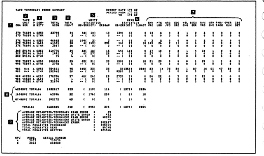
Figure 4.2 Tape Permanent Error Summary
Tape Permanent Error Summary
This report describes in more detail, the permanent errors that appear on the Tape Subsystem Exception report. The errors are grouped under either hardware or volume/creating drive, and are listed by CUA or ValID (volume serial
number) in the order that they occurred.
Notes:
1. R W E. These letters indicate which kind of permanent error is
involved: READ, WRITE, or EQUIPMENT CHECK.
2. CMD. The command code from the CCW in the OBR record.
3. FLG. The flag byte from the CCW in the OBR record.
4. CNT. The byte count from the CCW in the OBR record. 5. CSW32-63. Bits 32 - 63 of the CSW in the OBR record. 6. SENSE. The sense bytes from the OBR record.
7. HDR SER. The serial number of the creating drive.
[image:34.612.66.569.94.292.2]3420/3803 REFERENCE GUIDE
IJ ...
'\
TA" T,",ORAIY 11101 'U""AIY RIPOIT DATI 17. II
fJ cD II II II, PlRlaD ,.0" TO 1'0 171 II II
TAPI IIRnE IIAD III f
IITI .RC ICC VII. IKIW R"! lIT" 'AI' OVII Z . .
I.IC .IPC CRC CHG IRI VRC CHK TACH IUN DIT
. . CUA ~~lT U ISTY , DIH- TDTAI. '%01 TOTAl. "OUNT ",.II1RI eTl ITATUTIe • II . . ' " "I'I . . ITATIITIe. ICTI CLNAeT VIC INV
:l7D " i n A ' •• 0 1:1795 I ' 4" 101 ,10 1391 31 0 13 I I 1 I I
•
•
17D , . . . . A OTH. 17 I -- I 01 0 -- I 01 0 0 0 0 0 0
•
0•
I
•
•
•
•
I•
•
• •
"
•
U•
,
0 0•
•
10 0 0 0 0 0 0 0 0 0
171 " . . . A 6110
'''61
n 1991 :II :I -- I 01 0 :I171 76190 A 1600 '1'31
..
41 1'91 131 141 II II 1.9371 ,.... A OTH. 1167 16 -- I 01 0 -- I OJ 0 0
II I
•
1•
10 1 0•
11 I 1 I 1 I 0
• • •
0 0 I 0 0
•
•
0 I I3D' 5914' A 'ISO 110776 3' lie 111 11 '4e 111 0 17
leI 19146 A 110. 14.1 I oc 171 ZI -- I OJ 0
.,
301 19146 A OTH.
,.
,
-- e 01 0 -- I 01 0 019
• •
I 1a,
1 I I 10 0 0 I 0 0
•
0 0•
99. 711., A UIO lO . . n II 31e 111 10 1S01 11 II 11
992 '519' A OTHI I'"
,
.- I 01 0 -- e 01 0 0.11 N'" A UIO ' . . IU ' I lOll 3JI 33 31131:11 lioo .3 1K 7J 54 1 17 IK ' I 47
.0
•
911 H". A OTHI lSI'" U -- I 01 0 9111 11 0 1 I 0 0 0
•
1 0 1 0 0II 3
•
:I II• • •
0 0 0 0 0 0 I
•
. . I 4OSIO A U'O 171:111 17 4" Z41 15 1711 II 0 14
til 40550 A 11000 174 1 -- I 01 0 -- I 01 0 0
' I I 40550 A ,OTHI 11674
,
-- I OJ 0 -- I 01 0 0 0 0 0•
•
•
0•
{'ZlOIP' TOTAI. •• 14311" III I 1191 116 I 1:1711 l i l t
III 16001111 TOTAU. 610 . . I I I 1761 IS. I II II
OTH_aPr TOTAU' 191171 IS OJ 11
TOTAU. 1611015 140 I .'11 :171 I 13751 1154
{ .... d. _mM""'"' ...
= 19AVIRAGE "EGAIYTEI.lTE",aUIV 'IIUTI IIROII : 4ZZ
,AVIRAGI HEGAlYTEVP'I"AHENT READ IIRaR • 4OJ74
II AVERAGE "EGAIYTEVP'I"ANIHT IIUTI IRIOR •
AVEIAGE HE~AIYTlS.lPER"AHZHT ERROR : 101657
TOTAl. HEGAIVTE. PROCEIiIO = Z05314
TOTAl. H'GAIYTES READ : 10'"
TOTAl. "EGAIYTII IIUTTIN • 124166
CPU HODEL SERUI. HUHI . .
A 1033 707070
1 lOll 101010
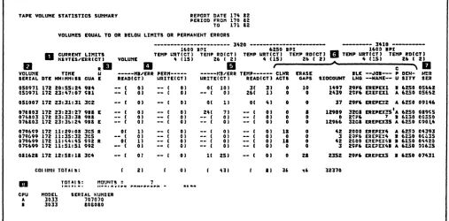
Figure 4.3 Tape Temporary Error Summary
Tape Temporary Error Summary
This report presents all the temporary read/write errors recorded for the hardware during the report period. The LIMIT control values specified when in-voking EREP are ignored for this report.
Notes:
1.
2.
3.
EREP
CUA and DENSITY The errors are listed by CUA and density.
TAPE UNIT SER. The serial number of the tape unit. If this informa-tion is not available because the CUA did not have a permanent error, N/A will appear in this field.
TOTAL SIOS. The number of SIOs issued against this device at this density.
4.16
C
JC
(~' '~r
\..",/ I ' \...,l("
,
i "'-.j /"-" ~ .~/ ~.
,
,./ ., , \ .... . / ,I f '
, '
[image:35.612.65.584.85.392.2](
(
(
(
(
(
(
(
(
(
',-, ,./
(
(
(-(
('
{'
('
{
3420/3803 REFERENCE GUIDE
4. TOTAL MOUNT. The number of volume mounts for this device at this density.
5.
6.
7.
8.
9.
EREP
WRITE STATISTICS. This area lists the actual number of megabytes written per temporary write error, and the actual number of temporary write errors, by this device at this density. The total number of erase gaps on this device at this density, are listed under the ERSGAP heading.
READ STATISTICS. Thi s area 1 i sts the actual number of megabytes per temporary read error, and the actual number of temporary read errors. The total number of cleaner actions on this device at this density, are listed under the CLNACT heading.
These eleven columns contain counts from the statistical data that is re-corded in the OBR records, as follows:
ENV VRC
MTE LRC
SRC/PC
EDC CRC
VEL CHG SKEW ERR R/W VRC
WTM CHK PAR/TACH
OVER RUN IBG DET
total envelope/vertical redundancy check count
total multitrack error/longitudinal redundancy check count
for 3420, the total start read check count; for 3410, the total parity compare count
total end data check/cyclic redundancy check count total velocity change count total skew error count
total read/write vertical redundancy check count
total write tape mark check count for 3420, the total partial record count; for 3410, the total tach check count
total overrun count
total interblock gap detected count
Totals of SIOs, mounts, write, and read statistics for each tape density.
Averages and totals for megabytes of data processed during the report pe-riod.
;;0
1
TAPE CUA STATISTICS Su:tHARY FOR - .981 REPO~T DATE 11~ 12 ~
rn N
"
PERIOD FRO" I1t 12 0TO 171 12
"'-w
-~---1600 IPI 3420 ---6250 IPI 00 0
w
D CURRENT UnITS TEMP URT(Cf) TEMP RD(CTJ TEHP URT(Cf) TE"P RD(CT J
;;0
. nBYTES.I'Ep.RICT) HARDUARE ,. lISJ 26 ( 2J ,. [IS) 26 ( 2J
rn
D.
a
0C
D
D"
IJ ,... rn
VOLUHE fJ TIHE U ----HI.I'ERR TEtfP---- 'ENV "T£ POST C/P CRC URTG --SLOU-- CHAN ERLf PART TIE ' P !)EN- H!:R ;;0
SERIAL DTE HH:"":SS E URITE(CT) READ(CT) SIOCOUNT VRC LRC AHIL CO"P III VRt BEG EUD BUFF IRIC REC P 01 U SITV S::;:11 rn z:
n
rn
07£681 170 23:20:54 ( 0) ( 0) 35 0 0 0 0 0 0 0 0 0 0 o 00 A ~2S0 005~O
(j)
079115 170 23:5':~1
•
0) [ OJ J! 0 0 0 0 0 0 0 0 0 0 o 00 I 6250 005~O c:073698 172 00:40:47
•
OJ ( OJ 126 0 0 0 0 0 0 0 0 0 0 o 00 B 6~~0 C~2IC I - f&50298 172 00:46:59
•
OJ ( OJ 228 0 0 0 0 O· 0 0 0 0 0 o OG B 6~~0 C5~:2 0 07£212 172 00:51:01 ( 0) 11 1) 135 0 1 0 0 1 0 0 0 1 0 P 00 ! tcSo 02~16 rnG7S3~7 172 00;51:12 ( 0) ( OJ 175 0 0 0 0 0 0 0 0 0 0 o co I t~~O 0~:1~
07~727 172 01:13:42
•
0) ( OJ 4652 0 0 0 0 0 0 0 0 0•
o 00 A 6~50 02~13 060'!6 172 04:20;23 ( 0) ( OJ 9110 0 0 0 0 0 0 0 0 0 0 o 00 A 6250 0~153 071540 172 05:53:07 ( 0) ( 0) 44 0 0 0 0 0 0 0 0 0 0 o 00 ! '250 00550 079146 172 07:~3:21 ( 0) ( OJ 5890 0 0 0 0 0 0 0 0 0 0 o CO B 6250 OCS:OoaO~81 172 07:55:17
•
OJ ( OJ a774 0 0 0 0 0 0 0 0 0 0 o 00 A 6250 0~3~6020281 172 01:03:26 ( OJ ( OJ 11568 0 0 0 0 0 0 0 0 0 0 o 00 I 6250 C<3~6
i 0:0472 172 03:09:43 (
OJ ( OJ 1317a 0 0 0 0 0 0 0 0 0 0 0 o CO A t2~0 1tZl0
['
071573 172 oa:21:53 ( 0) ( OJ 201e9 0 0 0 0 0 0 0 0 0 0 0 o 00 A 6250 12310
!
~ 071535 172 03:31:01 Ot3~69 172 01:53:07 ( ( 0) 0) ( ( OJ 15059 0 0 0 0 0 0 0 0 0 0 0 000 A OTr.~ Italc OJ 16331. 0 0 0 0 0 0 0 0 0 0 0 o 00 A CTH~ 22~E6
I - ' 061915 172 12:01:01 ( OJ ( OJ 1l~5
0 0 0 0 0 0 0 0 0 0 0 o 00 A 6253 Ot&C7
00 07575& 172 17:32:5~ ( 0) ( OJ
1724 0 0 0 0 0 0 0 0 0 0 0 o 00 A "SO c~·~t2
07a763 172 17:50;~9 ( 0) 27( 2) 50~4 0 0 0 0 0 0 0 0 0 0 0 P 00 A teSO OO!i!l C65746 172 1&:10:0~ ( OJ ( 0) 36 0 0 0 0 0 0 0 0 0 o 00 B 6CSO OC~:O
OS3273 172 11:53:47 ( OJ ( 0) 4216 0 0 0 0 0 0 0 0 0 o 00 I 6e:0 051a& 054315 172 19:21:56 ( 0) ( 0) 19~2 0 0 0 0 0 0 0 0 0 o CO B 6c50 O~!~2
072125 172 19:51:36 ( 0) ( OJ 111 0 0 0 0 0 0 0 0 0 o 00 B t250 OC5:~
07126& 172 20:41:45 ( 0) ( OJ 40 0 0 0 0 0 0 0 0 0
o 00 B 62S0 005!i~
172 21:10:26 ( OJ
.-
( 0) I 0 0 0 0 0 0 0 0 0 o 00 A OTH~ 005;~051956 172 21:19:24 ( OJ ( OJ 246 0 0 0 0 0 0 0 0 0 o 00 A ~250 OCS:O 065161 172 21:32:50 11( 3J ( 0) 5030 3 3 0 0 0 0 1 3 0 o ID I ~2~0 005:0 06tS14 172 21:40:53 5&( 1) ( OJ 5170 1 1 0 0 0 0 0 1 0 o 05 A 6250 OC:S~
C25034 172 22:00:05 .
--
( OJ ( 0) 19 0 0 0 0 0 0 0 0 0 o 00 B CTHR OC5S~076203 172 23:23:27 E 24( 7) ( OJ 12989 I I 0 2 0 0 5 I 0 o FF A 6250 ca~;s
076203 172 23:33:38 ( 0) ( OJ 0 0 0 0 0 0 0 0 0 0 o 00 B 6e:0 OCS=O
07~a03 172 23:36:24 E ( OJ ( OJ 12966 0 0 0 0 0 0 0 0 0 o 00 A 6250 OV014 063036 173 00:41:24
•
OJ ( OJ 21967 0 0 0 0 0 0 0 0 0 o 00 A 6250 oaoesCOLUttN TOTALS: ( 11) ( 31 190115 12 13 0 0 3 0 0 6 13
•
•
0 TOTALS: "aUNTS
=
32AVERAGE "EGAIYTES'TE"FORARY READ ERRO~
=
lJ"3AVERAGE nECAIYIES"EHPORARY utIlE ERROR
=
S5CPU nODEL SERIAL HUttIER
A 3033 707070
I 3033 loaoao
Figure 4.4
TAPE CUA STATISTICS SUMMARY
~
rJ
~
~('I
p ...
() ()
(~\"
f \ f \ / \ fc" \CO)
f \ ["'"()
n
~:~\...
--) ) \./ '\ \c ./
. ) } \. \ .. ) \ } )
[image:37.791.57.740.75.592.2](
(-(
(
(
(
('
(
(
(-
(--c/
3420/3803 REFERENCE GUIDE
Tape CUA Statistics Summary
One of these reports is generated for each device (CUA) that appears as a hardware exception on the Tape Subsystem Exception report. The report pre-sents the CUA's temporary errors that failed the limits set in the LIMIT con-trol statements. The errors appear by volume ser.ial number in the order (date and time) in which they occurred.
Notes:
1. CURRENT LIMITS. Because the report deals wi th temporary errors, the current LIMIT values for hardware appear for comparison.
2. DTE. The date and tim!:! are from the OBR record. 3.
4.
5.
6.
EREP
R W E. This column contains the permanent errors against this volume.
An R indicates read errors, a W indicates write errors, and an E indi-cates equipment checks.
MB/ERR TEMP. The actual error count and error frequency for thi s vo 1-ume mount.
SIOCOUNT. The number (from the OBR record) of START ·I/O instructions issued against this CUA while this volume was mounted.
These eleven columns contain counts from the statistical data that is re-corded in the OBR records, as follows:
ENV VRC
MTE LRC
POST AMBL C/P CaMP CRC II I WRTG VRC
SLOW BEG SLOW END CHAN BUFF ERLY BRBC PART REC
TIE
total envelope/vertical redundancy check count
total multitrack error/longitudinal redundancy check count
postamble count c/p compare count
cyclic redundancy check iii count write trigger vertical redundancy check count
slow begin read back check count slow end read back check count channel buffer count
early begin read back check count partial record count
track in error parity bit (P) and byte (07)
3420/3803 REFERENCE GUIDE
7.
8.
9.
EREP
DENSITY. From the mode byte in the OBR record.
HDR SER. The serial number of the creating drive. from the tape header.
Totals and averages of the data presented in the report.
4.20
;:/
c
c'
(
(
[
(
'"j
c
3420/3803 REFERENCE GUIDE
TAPE val~E STATISTICS S~IIART REPORT DATE 174 12 PEIIOD FRDII 170 a2 TO 171 112 VOlUIIES EQUAL TO DR IElOU lllllTS DR PERIIANENT ERRORS
--- l420 ---11>00 apl 6250 IPI
lUI
~~~~:~~~~~~l TEIIP IIITICTI TEIIP RDICTI TEIIP IIRTICTI TEIIP RDICTl VOlUIIE 4 1151 26 I 21 4 USI 2r. I 21fJ RII
a
II,
VOllr.IE TIllE II ---III'EIR PERII--- ---II"EIR TIIIP--- CLNR ERASE
- - - - l410 - - - - -16C~ IPI
II TEIIP WTICT I TEIIP RDICTI "'" 4 1!51 26 I 21
C , I I
IlE --~OI---P DEN- HIlR
SERIAL DTI HM'""'SS CUA E .EADleTl IIRlTEleTI IIRlllleT I IEADICTI ACTS GAPS srOCIIUIIT lNG --NAIIE-- U SlTY SEll
050971 172 20.55.24 914 -- I 01 -- I 01 01 101 II II 0 10 1497 29... ERIPEXI I 6150 onu
05~971 172 2l.47:07 ~Il -- t 01
--
( 01 -- I 0) 261 1) 0 0 2U9 211F6 ERIFIXI A 6250 05662051007 172 23.31:31 3C2 -- t OJ -- I 0) O( 11 Ot 41 0 0 l7 29 ... EREPeZ '" 6ZS0 09146 07 •• 03 172 2l.2l:27 'III I -- t 01
--
( 01 24( 71--
( 01 0 I 12919 32C1 EREPEX!SI", 6250 019~507610l 172 2l.3l:l. 91' -- I 01 -- I 01
--
( 0)--
( OJ 0 0 0 2':F6 7 I 6130 COS50076aOl 172 2l.l6:2' 911 E -- t 01
--
( 0) -- I 01 -- I 01 0 0 12966 Ue& ER£PEX3S '" 6250 C901,.4 079699 172 11:29.0& 3CS II 01 11 -- I 01 -- I OJ -- I 01 11 0 4Z 2000 ERIPIX' '" 6250 0439l 079699 172 11.l5:l2 lC5 -- I 01 -- I 01 -- I 01 -- I OJ 0 0 1 2QF6 EREPE:::4 I 6130 oe~l507.6 •• 172 11:44.45 ;92 R 0( 11 -- I 01 -- I OJ -- I 01 11 0 4Z 2eoo ERIPE:::~I I 6i50 04420 079699 172 11:51:51 .92
--
( 01 -- I 01 -- I 0) -- I 01 0 0 1 29F6 EaE~EX41 '" 6250 OQ6~5011621 172 12:51:11 lC4 -- I 01
--
( 01 11 251 -- I OJ 0 21 2lSZ Z9F6 ERIPEXS • 6250 07431COl 111111 TOTAl I: 21 01 411 II U
" uno
III TOTALS: I1DUIIT!! = 7.
tH'''' -.
...
,....
~ .. ,." ... ~...
"-CPU IIODEl SERIAL NUllDEIL
A lOll 707070
•
lOll 101010Figure 4.5 Tape Volume Statistics Summary
Tape Volume Statistics Summary
This report shows all the activity for every volume listed as an exception on the Tape Subsystem Exception report. Entries are grouped by volume serial and listed in chronological order.
Notes: 1.
2.
3.
4.
5.
EREP
CURRENT LIMITS. Because the report i ncl udes temporary errors, the
current LIMIT values for volumes appear for comparison.
VOLUME SER IAL. There is no volume seri a 1 number i f the tape is un 1
a-beled or cannot be read.
R W E. This column contains the permanent errors recorded against this volume. An R indicates read errors, a
W
indicates write errors, and an E indicates equipment checks.MB/ERR PERM. The error count and frequency for permanent read and
write errors.
MB/ERR TEMP. The error count and frequency for temporary read and
write errors.
[image:40.612.61.568.97.347.2]3420/3803 REFERENCE GUIDE
6. Except for the CPU indicator, these columns contain information taken from the OBR record:
CLNR ACTS ERASE GAPS SIOCOUNT BLK LNG
JOB NAME DENSITY
cleaner action count erase gap count
start I/O instruction count
block length from the OBR record: or the average block length
the job name
tape density, from the mode byte from the OBR record
7. HDR SER. The serial number of the creating drive. 8. Totals for the volumes on this report.
EREP 4.22
o
o
o
c
o
c
c
(
(--,
(
(-[
(
(
(
(
(
3420/3803 REFERENCE GUIDE
LIMIT Control Statement
The LIMIT control statement allows you to set the error thresholds, or limits, that you want EREP to use for the Subsystem Exception reports. The keyword values you specify on the LIMIT statements control the printing of temporary and soft errors: the reports include data only for devices with errors that equal or exceed any of the limits that you specify.
The format of the LIMIT statement is:
{
daSd,d 1 [,d 21 ••• }
LIMIT tape,tl [,t2) . . .
cpu,.cl [,c 2 )···
where d, t, and c are product-dependent keyword parameters with associated nu-meric limits.
IItape" can be one of the fo 11 owi ng: 34XX
3410 3420
34XX is a general device type designation that includes both 3410 and 3420. When you code 34XX on a LIMIT statement, you are requesting that the limits apply to all devices of the general type.
Coding the LIMIT Statement
o
o
o
o
"LIMIT" must be the first character in the statement, followed by one blank and keyword parameters separated by commas.
There is no limit on the number of statements you may code. However, on-ly one 34XX statement is allowed.
If you code a second LIMIT statement for one specific device type, its values override those set in the first statement. EREP uses the limits set in the latest LIMIT statement.
The limits you specify on the LIMIT statements apply only to temporary errors for tape.
The keyword parameters for the LIMIT statement, and some aspects of the limit-i~g action, differ depending on whether you are coding for DASD, tape, or processor/channel. Therefore, the tape group is described separately on the following pages.
Using the LIMIT Statement for Tape (34XX)
3420/3803 REFERENCE GUIDE
The limiting action works differently for tape devices than it does for DASD. You need two sets of keyword parameters for each device type, and you must specify which tape density the limits apply to.
The valid keywords for tape drives are:
To Set Limits For:
1600 BPI Temporary Errors
Hardware read
Hardware write
Volume read
Volume write
6250 BPI Temporary Errors
Hardware read
Hardware write
Volume read
Volume write
where:
nnn
Use Keyword:
HR1600=nnn(ct)
HW1600=nnn(ct)
VR1600=nnn(ct)
VW1600=nnn(ct)
HR6250=nnn(ct)
HW6250=nnn(ct)
VR6250=nnn(ct)
VW6250=nnn(ct)
is a 3-digit decimal value representing the number of megabytes of data processed between errors (MBYTES/ERROR).
(ct)
is a decimal value from 1 to 99 representing the number of errors en-countered before the device or volume appears on the Subsystem Exception report.
EREP uses both these values to establish thresholds for temporary errors. If the number of errors recorded against the device or volume is greater than the count (ct) value, AND the average number of megabytes of data processed be-tween errors is less than the error frequency (nnn) value, then the device or volume will appear on the Tape Subsystem Exception report.
Notes:
1. If you do not code LIMIT statements for a tape device or volume, the Tape Subsystem Exception report includes only the permanent errors recorded against that device or volume. However, all temporary errors appear in the Tape Temporary Error Summary.
EREP 4.24
~.I
c
o
C\
, Irl ". I .
\ ... /
c~
c
r,
(
(-(
(
[
(
(
(
(-'
3420/3803 REFERENCE GUIDE
2. You should specify all LIMIT values. Results are unpredictable if any values are omitted, or if a value is coded as a O.
3. 34XX includes only 3410 and 3420 tape drives.
4. The density of 6250 BPI applies only to 3420 drives. If coded on LIMIT statements for 34XX, it is ignored for 3410 devices.
5. If a tape drive is operating at a density other than 1600 or 6250 BPI, EREP uses the LIMIT values you specify for 1600 BPI.
6. Only one LIMIT statement for 34XX is allowed.
7. You cannot continue a LIMIT statement from one line to the next. Gener-ally, you should use separate LIMIT statements to establish hardware and volume limits for a device. If the device operates at both 1600 and 6250 BPI, you must use separate statements. However, if only one tape density is involved, you can combine all four keywords on the same LIMIT state-ment. For example, you might want to see only some of the temporary errors for your 3410 and 3420 drives, operating at 1600 BPI density, as follows:
Hardware
Read - 1 or more errors, at 25 megabytes/error Write - 15 or more errors, at 10 megabytes/error Volume
Read - 1 or more errors, at 25 megabytes/error Write - 15 or more errors, at 10 megabytes/error
To set these limits, you could code the following LIMIT statements:
LIMIT 3410,HRI600=025(1) ,HW1600=010(15) ,VR1600=025(1) ,VW1600 =010(15) LIMIT 3420,HR1600=025(1) ,HW1600=010(15) ,VR1600-025(1) ,VW1600 =010(15)
Since the limit values and density are the same, these two statements could be combined into a single 34XX LIMIT statement:
LIMIT 34XX,HR1600=025(1),HWI600=010(15),VR1600=025(1),VW1600=010(15)
<t
·1'
(
(--(
(
(
(
...j
(
c
",r-
c--3420/3803 REFERENCE GUIDE
READ/WRITE SERVICE TECHNIQUES
Temporary/Permanent Errors
The primary cause of write data checks is the type caused by a loss in signal from the tape on readback during write. On the 3420 tape subsystem when tape is wri tten, the amp 1 i tude is checked to en sure there is suffi ci ent amplitude
written on tape to be read at a later date. This write checking level
(threshold) is higher than the threshold at which the tapes will eventually be read. If the amplitude of the read signal goes below the threshold, a temporary wri te error occurs and the error recovery program (ERP) takes control. ERP does a back space record {BSR), then performs an erase gap before retrying the write operat ion. If the wri te is then error-free, one temporary write error is logged
and normal operation continues. If the retried write operation again fails
another erase gap, then write is performed, This is continued until the write is successful or until fourteen tries to write the record have occurred. In that event one loop write-to-read command is tried. If successful, one more erase gap, write is attempted. If it again fails (fifteenth time), a permanent write error is posted.
If the write command is successful on retry number 10, EREP would show nine erase gaps (actual number) but only one temporary write error. The reason for this is that write errors occurring while ERP has control are not logged to EREP while all erase gaps are.
Several causes of data check on tapes are:
1. Defects in oxide on tape. 2. Dirty tape
3. Dirty tape path 4. Edge damage on tape S. Contamination on head
6. Tape drive failures (ex. pneumatics, capstan, R/W circuitry)
When