3215 IJSTR©2019
Experimental Study Of Slip-In Haunched Gusset
Plate Connection For Double Lipped
Cold-Formed Steel Section
Muhammad Firdaus, Anis Saggaff, Mahmood Md Tahir, Shek Poi Ngian, KM Aminuddin, Fathoni Usman, Saloma
Abstract:— Connections on the cold-formed steel (CFS) section become an interesting topic concerning its failure mode that the thin-walled behaviour controls it. CFS weakness is usually caused by early local buckling and local instability. The bolt connections and the gusset plate are the easy way to install a joint of steel structures on CFS application. This study is aimed to investigate the behaviour of the CFS connection of double lipped channel C-sections of C20019 for the beam and C30024 for the back-to-back column with a slip-in haunched gusset plate. The haunched gusset plate is S275 steel grade, 6 mm thickness connected with M12 bolt. The experiment was carried out by isolated joint test to acquire moment capacity and rotation of the connection. It is observed that the connection failure modes were on the beam bolt and the local buckling on the column flange. The existence of the slip-in gusset plate reduces the buckling effect induced by the behaviour of the thin plate. The moment of joint (Mj) obtained from the experiment was 20 kNm, the stiffness (Sj) was 250 kNm/rad, and the rotation at the final load was 0.079 radian. The comparison moment of joint by analytical and experimental was 0.78, while the ratio of stiffness was 2.04. The analytical and experimental comparison between moment of joint and moment resistance of beam was 0.55. It concluded that the connection was categorized as partial strength and ductile connection for cold-formed steel section application.
Index Terms:— Cold-formed steel; gusset plate; connection; partial strength; moment of joint
—————————— ——————————
1
I
NTRODUCTIONIn recent centruies, the cold-formed steel (CFS) section was used as a secondary structure, including rails, roof purlins, wall cladding and even residential buildings at the middle level [1], [2]. Connections between cold-formed steel members are generally considered to be shear connections with two bolts per member [3] while some can be created of hot-rolled steel combined with bolts and angle cleats [4]. However, some of the studies have proven that early local buckling and instability mostly happen at the CFS [5], [6], because of the thin-walled behaviour. In recent years, the experiments of light steel joints combine with gusset plates and bolts have been carried out intensively by several researchers, due to the limited design guidelines in Eurocode 3 for this type of connections. The choice of bolts, besides being compatible with gusset plates, it is also relatively easier and requires no special skills to install compared to welding joints [7]. Tan in [8] and Aminuddin in [9] have experimented the slip-in gusset plate in rectangular shape with 6 mm of thickness for cold-formed steel connections using back-to-back double lipped channel C-sections. The same beam size of 200 mm was used for both experiments, while the column depth was different with a depth of 250 mm and 300 mm respectively.
From the study, the moment of joints was almost the same with 14.27 kNm and 15.68 kNm. Bucmys [7] also investigated the cold-formed connection using T-shape gusset plate 12 mm of thickness. The joint capacity was 25 kNm. The study as in [7] – [9] show that the slip-in gusset plates can increase cold-formed steel joint capacity to achieve the behaviour of partial strength connection. The CFS joints with haunched gusset plate have been studied by Bucmys as in [10] with the C-profile section, and by Sabbagh with the curve flange C-profile section [11]. The two researchers only investigated the behaviour of the connection based on a numerical study using finite element analysis (FEA). Based on the experimental and numerical studies, it can be said that the shape and the thickness of the gusset plate could influence the moment of joint. The presence of a slip-in gusset plate could reduce the buckling effect of the cold-formed cross-section caused by the behaviour of thin plates. This paper covers the experimental investigation of slip-in haunched gusset plate connection for cold-formed steel sections on beam and column joint, where not many researchers have studied in-depth. The experiment was done on isolated joint, with the purpose to obtain the moment-rotation and stiffness of the connections and validated with other researchers. The proposed connections were expected to classify as partial strength connections.
2 T
HE MATERIAL AND METHODSThe experiment on the specimen was carried out on isolated joint test where the cantilever beam has lateral restraint, and the end of the beam has loaded by a load cell. The specimen was installed by fabricating 3 meters length column with 1.1 meters length beam. The joint between beam and column used hot-rolled haunched gusset plate in steel grade S275 and the thickness of 6 mm. The nominal yield stress (fy) and the ultimate tension stress (fu) were 275 MPa and 430 MPa, respectively. The isolated joint was executed to obtain the characteristic of the connection, i.e. moment of joint (Mj) and stiffness (Sj) [12]. This study was held in Steel Structure Laboratory of Civil Engineering Department, Universitas Sriwijaya. The preparation of the specimen is presented in Fig.1. The cold-formed steel G450 was used with yield stress ————————————————
• Muhammad Firdaus is PhD. student of Civil Engineering, Faculty of Engineering, Sriwijaya University, Indonesia. Corresponding Email: [email protected]
• Anis Saggaff, KM Aminuddin, and Saloma Civil Engineering Department, Faculty of Engineering, Sriwijaya University, Indonesia.
• Mahmood Md Tahir, and Shek Poi Ngian, Construction Research Centre (CRC), Faculty of Engineering, Universiti Teknologi Malaysia, 81310 Skudai, Johor Bahru, Malaysia
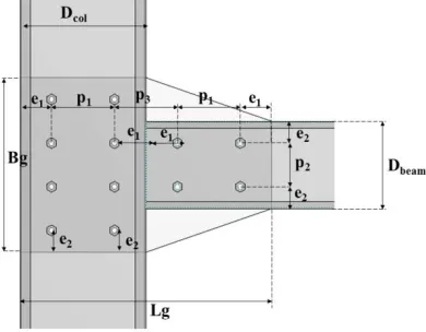
(fy) 450 MPa and ultimate tension stress (fu) = 480 MPa. The section of double lipped channel was installed back-to-back to increase the moment inertia and to delay the local buckling [6]. The section of the beam is C20019 with 200 mm of depth, 76 mm of width, 1.9 mm of thickness and 1.1 m of length, while the column section was C30024 with 300 mm of depth, 96 mm of width, 2.4 mm of thickness and 3 m of length. All of the bolts grade 8.8 M12 were installed with yield stress (fy) = 640 MPa and ultimate tension stress (fu) = 800 MPa, refers to a study in [13]. Two inclinometers were located at the beam (Inc-beam) and column (Inc-col) to measure and record the rotation of the connection. Four LVDT were positioned at the beam (LVDT-2 and LVDT-1) and column (LVDT-3 and LVDT-4) to obtain the horizontal and vertical displacement of specimens. The configuration of the haunched gusset plate is presented in Fig. 2. Table I shows the dimension of connections and the position of the bolt. The distance between bolts was arranged according to the spacing requirements by EC3 [14].
TABLE1
THE DISTANCE OF CONNECTIONS (MM)
Bg Lg e1 e2 p1 p2 tg 409 600 50 50 200 200 6
Fig. 1. Isolated joint test configuration
Fig. 2. The dimension of connections
3 R
ESULTS ANDD
ISCUSSION3.1 Failure modes
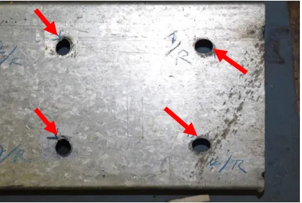
The test carried out by applying a point load that gradually increased by a hydraulic jack. Visual observation was carried out throughout the test. Fig. 3 (a) shows the beam rotated after the ultimate load reached 20 kN. The beam rotates, causing the bolt group to react so that the elongation occurs around the bolthole. Besides, the gusset plate does not deform significantly when compared to the beam. The beam rotation caused the column flange to be compressed at the bottom beam flange. The height compression stress was developed at the compression zone caused local buckling at column flange (Fig. 3 (b)). Fig. 4 shows the failure mode of the beam bolthole. Elongation of boltholes (i.e. red arrow in Fig. 4) indicates the bearing failure of the bolt due to the thickness of CFS that only 2 mm.
(a) Rotation of beam
(b) The compression at the bottom flange column
3217 IJSTR©2019
Fig. 4. The elongation of beam bolt hole
3.2 Load vs Deflection Curve
Load vs. deflection curves was obtained from LVDT-1 and load cell data that directly recorded by the data logger. Fig. 5 shows a height slope at a range of 1 – 4 kN. It could be due to bolts were fully tightened.
Fig. 5. Load vs deflection curve
The slope started to decrease after the load increased until the final load of 20 kN was reached. It was shown that the relationship between load-deflection is non-linear. The maximum deflection before the graph become plateau or decrease is 148.48 mm.
3.3 Moment vs rotation curve
Fig. 6 presents the moment-rotation curves of the connection. The moment was obtained by multiplying the load (P) with a distance of about 1 m from the load cell to the face of the column flange. The rotational data were taken from the difference of beam rotation and column rotation in radians. The graph shows that the ultimate moment of the joint was 20 kNm and the rotation of 0.079 rad. The stiffness was taken from the slope of the line with a result of 250 kNm/rad. The test object was categorized as ductile as the elastic rotation is more than 0.03 rad.
Fig. 6. Moment vs rotation curve
3.4 Analytical calculation
Based on observations of the failure modes, the elongation of beam bolt holes was clearly visible. The failure implies that the minimum resistance of the joint occurs at the group of bolts on the beam. Therefore, the analysis can be simplified by determining the moment resistance induced by the group of bolts on the beam as shown in Fig. 7. According to Fig. 7, the joint resistance is limited by shear and bearing resistance of the bolts [15]. The shear resistance of bolt can be calculated as:
𝐹 =
(1)
𝑭 =
= 33.17 kN
Where: 𝜶 = 0.6 for bolt grade 8.8; 𝒇 = ultimate strength of bolt; 𝑨= stress area; 𝜸 = 1.25
The bearing resistance depends on the thickness connected part with the equation:
𝐹 =
(2)
𝑭 =
= 27.65kN
Where: 𝜶 = 1; 𝒌 = 1; 𝒇 = ultimate strength; = the
diameter of bolt; = thickness of beam; 𝜸 = 1.25
Thus, the resistance of bolt (𝐹 ) is the minimum of 𝐹 and 𝐹 .
𝐹 = min (33.17, 27.56) = 27.56 kN Delta =
148.48 Pmax = 20
0 5 10 15 20 25
0 50 100 150
L
o
ad
(
k
N
)
Deflection (mm)
Mj,u,exp = 20
øj
,u,
exp
=
0.
079
øj
,0.
03,
exp
=
0.
03
Mj,0.03,exp = 8.43
Sj,Exp = 250
0 5 10 15 20
0 0.01 0.02 0.03 0.04 0.05 0.06 0.07 0.08
M
o
m
en
t
(k
N
m
)
Fig. 7. Moment of joint
The resistance of joint representing by moment-resistance is:
Moment joint (Mj) = number of bolt x 𝐹 x lever arm (3)
Moment joint (Mj) = 4 x 27.56 x 141.42 = 15.64 kNm.
The calculation of joint stiffness (Sj) for the haunched gusset plate was referred to Klich in [16]. The method of calculation was divided into three groups:
a. The stiffness of column bolt group (Sc,bg,ini) b. The stiffness of beam bolt group (Sb,bg,ini) c. The rotational stiffness of the gusset plate (Sgp,ini) d. The stiffness of column bolt group (Sc,bg,ini)
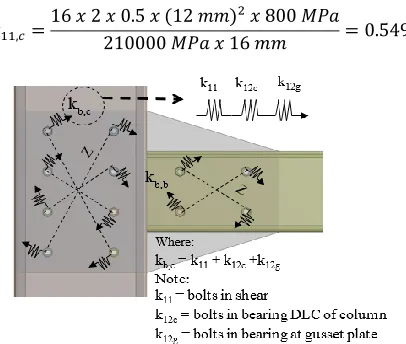
The spring models were presented with built from three component groups: i) bolt in shear (𝑘 ); ii) bolt-in bearing of
CFS (𝑘 ); iii) bolt in bearing for gusset plate (𝑘 ) [14]. Fig. 8 shows the component method of the stiffness column bolt group.
The stiffness coefficient of bolt-in shear as in Eq. (4):
𝑘 =
(4)
Where : 𝑐= number of shear plane; 𝑛 = 0.5 for single bolt; 𝑑 = diameter of bolt; 𝑓 = ultimate tensile strength; E = the elastic modulus; 𝑑 = nominal diameter of M16 bolt
𝑘 =
16 𝑥 2 𝑥 0 5 𝑥 (12 𝑚𝑚) 𝑥 800 𝑀𝑃𝑎
210000 𝑀𝑃𝑎 𝑥 16 𝑚𝑚 = 0 549
Fig. 8. Mechanical models of the stiffness of column bolt group
The stiffness coefficient corresponds to the bolts in bearing for column stiffness is calculated as follows:
𝑘 = (5)
𝑘 =
≤ 2 5 (6)
Where: 𝑛 = 0.5 for single bolt; 𝑘 = 1.25;
𝑘=1.5x2x1.9/16≤2.5=0.356 ; 𝑑= diameter of bolt; 𝑓= ultimate tensile strength of steel.
𝑘 =24 𝑥 0 5 𝑥 1 25 𝑥 0 356 𝑥 12 𝑚𝑚 𝑥 450 𝑀𝑃𝑎
210000 𝑀𝑃𝑎 = 0 137
Bolt-in bearing for gusset plate:
𝑘 = (7)
Where: 𝑛 = number of bolt (i.e. 0.5 for one bolt); 𝑘 = 1.25; 𝑘 = 1.5x6/16 < 2.5 = 0.563; 𝑑 = diameter of bolt; 𝑓 = ultimate tensile strength of gusset plate
𝑘 =
24 𝑥 0 5 𝑥 1 25 𝑥 0 563𝑥 12 𝑚𝑚 𝑥 430 𝑀𝑃𝑎
210000 𝑀𝑃𝑎 = 0 208
The equivalent of the stiffness coefficient:
∑1 𝑘=
1 0 549+
1 0 137+
1
0 208= 13 928
The equation of stiffness of the column bolt group is shown in Eq. (8):
𝑆 =
(8)
Where: E = the elastic modulus; z = lever arm of the bolt
The outcome of the column bolt group's stiffness used Eq. 8 and presented in Table 2 below.
TABLE2
THE STIFFNESS CALCULATION OF COLUMN BOLT GROUP
Bolts E (MPa) Z (mm) 1
∑ 𝑘
𝑆 (kNm/rad) 1 210000 167.705 13.928 424.055 2 210000 167.705 13.928 424.055 3 210000 90.139 13.928 122.506 4 210000 90.139 13.928 122.506 5 210000 90.139 13.928 122.506 6 210000 90.139 13.928 122.506 7 210000 167.705 13.928 424.055 8 210000 167.705 13.928 424.055
Total 2186.244
Hence, the stiffness of the group of column bolts (𝑆 ) was 2186.244 kNm/rad.The calculation of Sb,bg,ini is similar to the Sc,bg,ini. Fig. 9 presented the component method of the stiffness of the column bolt group.
3219 IJSTR©2019
Fig. 9. Mechanical models of the stiffness of beam bolt group
Bolt-in shear as follows in Eq. (4).
𝑘 =16 𝑥 2 𝑥 0 5 𝑥 (12 𝑚𝑚) 800 𝑀𝑃𝑎
210000 𝑀𝑃𝑎 𝑥 16 𝑚𝑚 = 0 549
Bolt-in bearing for beam stiffness as follows in Eq. (5) and Eq. (6).
𝑘 =24 𝑥 0 5 𝑥 1 25 𝑥 0 356 𝑥 12 𝑚𝑚 𝑥 450 𝑀𝑃𝑎
210000 𝑀𝑃𝑎 = 0 137
Bolt-in bearing for haunched gusset plate as follows in Eq. (7).
𝑘 =
24 𝑥 0 5 𝑥 1 25 𝑥 0 563 𝑥 12 𝑚𝑚 𝑥 430 𝑀𝑃𝑎
210000 𝑀𝑃𝑎 = 0 208
The equivalent of the stiffness coefficient:
∑1 𝑘=
1 0 549+
1 0 137+
1
0 208= 13 928
The equation of stiffness of the beam bolt group as follows:
𝑆 =
(9)
The outcome of the beam bolt group's stiffness was shown in Table 3 below.
TABLE3
THE STIFFNESS CALCULATION OF BEAM BOLT GROUP
Bolts E (MPa) z (mm)
∑ 𝒌
𝑺 (kNm/rad) 1 210000 90.139 13.928 122.506 2 210000 90.139 13.928 122.506 3 210000 90.139 13.928 122.506 4 210000 90.139 13.928 122.506
Total 490.022
Hence, the stiffness of the group of beam bolts (𝑆 ) was
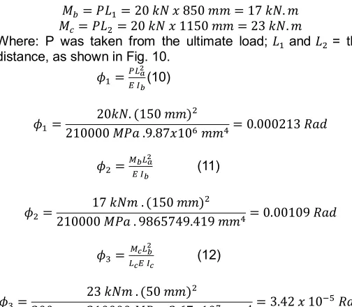
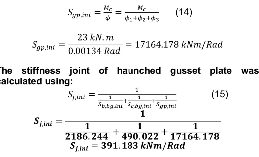
490.022 kNm/rad. The analysis of the rotational stiffness of the gusset plate has not been found in EC3. The calculation referred to Bucmys work in [7]. Fig. 10 shows haunched gusset plate rotation induced by point load (P) and moment (M). Furthermore, 𝜙 is rotation due to the beam's vertical load (P), 𝜙 is rotation due to moment on the beam (Mb) and 𝜙 is rotation due to moment on the column (Mc). The rotation of the gusset plate is a total of 𝜙, 𝜙 and 𝜙 as in Eq. (14).
Fig. 10. The rotation of haunched gusset plate
Therefore, the rotation of the gusset plate as follows:
𝑀 = 𝑃𝐿 = 20 𝑘𝑁 𝑥 850 𝑚𝑚 = 17 𝑘𝑁 𝑚 𝑀 = 𝑃𝐿 = 20 𝑘𝑁 𝑥 1150 𝑚𝑚 = 23 𝑘𝑁 𝑚
Where: P was taken from the ultimate load; 𝐿 and 𝐿 = the distance, as shown in Fig. 10.
𝜙 = (10)
𝜙 = 20𝑘𝑁 (150 𝑚𝑚)
210000 𝑀𝑃𝑎 9 87𝑥10 𝑚𝑚 = 0 000213 𝑅𝑎𝑑
𝜙 =
(11)
𝜙 = 17 𝑘𝑁𝑚 (150 𝑚𝑚)
210000 𝑀𝑃𝑎 9865749 419 𝑚𝑚 = 0 00109 𝑅𝑎𝑑
𝜙 =
(12)
𝜙 = 23 𝑘𝑁𝑚 (50 𝑚𝑚)
300 𝑚𝑚 210000 𝑀𝑃𝑎 2 67𝑥10 𝑚𝑚 = 3 42 𝑥 10
𝑅𝑎𝑑
Where: 𝐿 and 𝐿 = the distance on Fig. 10; 𝐼 = moment inertia of beam; 𝐼= moment inertia of column; E = the elastic modulus. Thus, the total rotation of the gusset plate:
𝜙 = 𝜙 + 𝜙 + 𝜙 (13)
𝜙 = 0 000213 𝑅𝑎𝑑 + 0 00109 𝑅𝑎𝑑 + 0 0000342 𝑅𝑎𝑑 = 0 00134 𝑅𝑎𝑑
𝑆 = =
(14)
𝑆 = 23 𝑘𝑁 𝑚
0 00134 𝑅𝑎𝑑 = 17164 178 𝑘𝑁𝑚/𝑅𝑎𝑑
The stiffness joint of haunched gusset plate was calculated using: 𝑆 = (15) 𝑺 = + 𝟗 + 𝟕 𝟕 𝑺 = 𝟗 𝒌𝑵 /
3.4 Discussion
The result of the experiment was compared with other researcher findings and presented in Table 4 and Table 5. Table IV presents the information about the shape and thickness of gusset plates that have been carried out by previous research and the current study. As shown in Table V, Aminuddin in [9] has experimented using a rectangular gusset plate; the ratio with the current study were 1.28 for moment joint and 0.12 for stiffness. The comparison with Tan in [8] presented a ratio of 1.40 for moment joint and 1.02 for stiffness. Tan used a rectangular gusset plate for connection beam-to-column but have different depth of column. A similar failure mode with the current study is found as well in [8] and in [9]. It is concluded that the local buckling at the column flange leads the need of the reinforcement at compression zone. Besides, the result in [9] also presented the bearing failure of beam boltholes. Based on the comparison as Table 5, it is found that the shape of the gusset plate could influence the joint performance as the study result in [17] and in [10].
TABLE4
COMPARISON MATERIAL WITH OTHER STUDIES
Comparison connection Type of
The gusset plate's thickness (mm) Depth of beam (mm) Depth of column (mm) Aminuddin (2017) Result Rectangular
gusset plate 6 mm 200 300 Tan (2011)
Result Rectangular gusset plate 6 mm 200 250 Current Study gusset plate Haunched 6 mm 200 300
TABLE5
COMPARISON RESULT WITH OTHER STUDIES
Comparison Mj, exp (kNm) Mj,exp Ratio (kNm/rad) Sj, exp Sj,exp Ratio
Aminuddin
(2017) Result 15.68 1.28 1948.06 0.12
Tan (2011)
Result 14.27 1.40 245 1.02
Current Study 20 1.00 250 1.00
To verify the experiment results, it is necessary to compare with analytical results based on failure modes observations. Table 6 and Table 7 presented the comparison of the moment
of joint from the experiment with analytical calculation and bending capacity of the beam. The ratio of Mj between analytic calculation and experimental results shows a good agreement with ratio value 0.78 while the ratio of stiffness joint (Sj) between analytical calculation and experiment was 1.56. Accordance with EC3, the partial strength classification was ranged by 25% Mcx < Mj < Mcx, where Mcx is the moment resistance of beam. The ratio for moment of joint experiment (Mj) and the moment resistance of beam (Mcx) was 0.55, which is more than 25% of the beam capacity. The connection is validated as partial strength.
TABLE6
COMPARISON WITH ANALYTICAL RESULT AND MOMENT RESISTANCE OF THE BEAM
Moment of Joint (Mj) kNm Ratio Mj,the/M j,exp Moment Resistance of Beam (Mcx) kNm Ratio Mj,exp/ Mcx Experiment Mj,exp. Analytical Mj,the.
20 15.64 0.78 36,611 0,55
TABLE7
COMPARISON WITH ANALYTICAL RESULT
Stiffness Joint (Sj) kNm Ratio Sj,the/ Sj,exp Experiment Sj,exp Analytical Sj,the
250 391.183 1.56
4 C
ONCLUSIONThe experiment of a slip-in haunched gusset plate connection on CFS section beam to column joint has successfully done. It can be concluded that:
1. The connection failure modes are located on the beam bolthole and the local buckling at the bottom of the column flange.
2. The ratio moment of joint (Mj) between the other studies have ranged from 1.28 to 1.40 while the ratio of stiffness is ranged between 0.12 to 1.02.
3. The comparison of analytic and experimental for moment resistance of joint was 0.78, and the ratio of stiffness was 1.56
4. The elastic rotation was found beyond of 0.003 radians. The ratio for moment resistance of joint (Mj) to moment resistance of beam (Mcx) was 0.55, therefore the slip-in haunched gusset plate with cold-formed steel section beam was classified as ductile and partial strength connections.
ACKNOWLEDGMENTS
The authors would like to thank Universitas Sriwijaya and Construction Research Center (CRC), Universiti Teknologi Malaysia for funding this research. The author is grateful Prof. Anis Saggaff and Prof. Mahmood MD Tahir for his guidance and help.
R
EFERENCES3221 IJSTR©2019
[2] I. Komara, E. Wahyuni, P. Suprobo, and K. Taskin, Assessing the Tensile Capacity of Cold-Formed Steel Connections using Self-Drilling Screws and Adhesive Materials (2018, no. 2). 2018.
[3] K. Chung and L. Lau, "Experimental investigation on bolted moment connections among cold formed steel members," Engineering Structures, vol. 21, no. 10, pp. 898-911, 1999.
[4] R. U. K. Nadya and F. Usman, "An experimental analysis on the moment rotation of beam-column connection using cold-form steel section," International Journal of Engineering and Technology (UAE), vol. 7, no. 4, pp. 668-673, 2018.
[5] Y. H. Lee, C. S. Tan, S. Mohammad, M. M. Tahir, and P. N. Shek, "Review on cold-formed steel connections," ScientificWorldJournal, vol. 2014, p. 951216, 2014.
[6] S. Haris, A. Prasetio, R. Thamrin, and H. Herman, An Experimental Study of Bending Behaviour of Double Channel and Hollow Sections of Light Gauge Steel (2018, no. 3). 2018.
[7] Ž. Bučmys and A. Daniūnas, "Analytical and experimental investigation of cold-formed steel beam-to-column bolted gusset-plate joints," Journal of Civil Engineering and Management, vol. 21, no. 8, pp. 1061-1069, 2015.
[8] C. S. Tan, M. M. Tahir, P. N. Shek, and A. B. H. Kueh, "Experimental Investigation on Slip-In Connection for Cold-Formed Steel Double Channel Sections," Advanced Materials Research, vol. 250-253, pp. 1038-1041, 2011.
[9] K. Aminuddin, A. Saggaff, and M. M. Tahir, "Experimental behaviour of beam-column connection using cold-formed steel sections with rectangular gusset-plate," in AIP Conference Proceedings, 2017, vol. 1903, no. 1, p. 020006, U: AIP Publishing.
[10]Ž. Bučmys and G. Šaučiuvėnas, "The behavior of cold formed steel structure connections," Engineering Structures and Technologies, vol. 5, no. 3, pp. 113-122, 2013.
[11]A. Bagheri Sabbagh, M. Petkovski, K. Pilakoutas, and R. Mirghaderi, "Ductile moment-resisting frames using cold-formed steel sections: An analytical investigation," Journal of Constructional Steel Research, vol. 67, no. 4, pp. 634-646, 2011.
[12]M. M. Tahir, A. Sulaiman, and A. Saggaff, "Structural Behavior of Trapezoidal Web Profiled Steel Beam Section using Partial Strength Connection," Electronic Journal of Structural Engineering (8) 2008, 2008. [13]M. Muhammad Lawan, "Structural performance of
cold-formed steel with self compacting concrete in a composite beam system," ed: Universiti Teknologi Malaysia, 2015.
[14]BS EN 1993-1-8:2005 - Eurocode 3: Design of steel structures . Part 1-8: Design of joints, 2005.
[15]BS EN 1993-1-3:2006 - Eurocode 3 : Design of steel structures : Part 1-3: General rules : Supplementary rules for cold-formed members and sheeting, 2006. [16]R. Klich, A. Kozłowski, and A. Wojnar, "Mechanical
model of bolted joints used in steel thin walled structures," presented at the The 12th International Conference on Metal Structures – ICMS, Wrocław, 2011.