Scholarship@Western
Scholarship@Western
Electronic Thesis and Dissertation Repository
9-30-2016 12:00 AM
Highly Efficient Resource Allocation Techniques in 5G for
Highly Efficient Resource Allocation Techniques in 5G for
NOMA-based Massive MIMO and Relaying Systems
based Massive MIMO and Relaying Systems
Xin Liu
The University of Western Ontario
Supervisor Xianbin Wang
The University of Western Ontario
Graduate Program in Electrical and Computer Engineering
A thesis submitted in partial fulfillment of the requirements for the degree in Master of Engineering Science
© Xin Liu 2016
Follow this and additional works at: https://ir.lib.uwo.ca/etd
Part of the Electrical and Computer Engineering Commons
Recommended Citation Recommended Citation
Liu, Xin, "Highly Efficient Resource Allocation Techniques in 5G for NOMA-based Massive MIMO and Relaying Systems" (2016). Electronic Thesis and Dissertation Repository. 4136.
https://ir.lib.uwo.ca/etd/4136
This Dissertation/Thesis is brought to you for free and open access by Scholarship@Western. It has been accepted for inclusion in Electronic Thesis and Dissertation Repository by an authorized administrator of
The explosive proliferation of smart devices in the 5-th generation (5G) network expects
1,000-fold capacity enhancement, leading to the urgent need of highly resource-efficient
tech-nologies. Non-orthogonal multiple access (NOMA), a promising spectral efficient technology
for 5G to serve multiple users concurrently, can be combined with massive multiple input
multiple output (MIMO) and relaying technology, to achieve highly efficient communications.
Hence, this thesis studies the design and resource allocation of NOMA-based massive MIMO
and relaying systems.
Due to hardware constraints and channel condition variation, the first topic of the thesis
develops efficient antenna selection and user scheduling algorithms for sum rate maximization
in two MIMO-NOMA scenarios. In the single-band scenario, the proposed algorithm improves
antenna search efficiency by limiting the candidate antennas to those are beneficial to the
rel-evant users. In the multi-band scenario, the proposed algorithm selects the antennas and users
with the highest contribution total channel gain. Numerical results show that our proposed
algorithms achieve similar performance to other algorithms with reduced complexity.
The second part of the thesis proposes the relaying and power allocation scheme for the
NOMA-assisted relaying system to serve multiple cell-edge users. The relay node decodes
its own message from the source NOMA signal and transmits the remaining part of signal to
cell-edge users. The power allocation scheme is developed by minimizing the system outage
probability. To further evaluate the system performance, the ergodic capacity is approximated
by analyzing the interference at cell-edge users. Numerical results proves the performance
improvement of the proposed system over conventional orthogonal multiple access mechanism.
Keywords: 5G; Massive MIMO; NOMA; Relaying; Resource Allocation
The completion of this thesis involves the contribution and supports by a great number of
people, thanks to whom my graduate study is a valuable and unforgettable experience in my
life.
I would like to express my deep gratitude for Prof. Xianbin Wang for offering me the
opportunity to study in the University of Western Ontario. His enlightening supervision and
foresight motivated me to identify the cutting-edge research topics, develop in-depth ideas and
achieve efficient research progress. His kind patience also helps my professional development
through exploration of different research methods. The research and communication ability I
learned from him will significantly benefit my future work and life.
I would also thank my colleagues, Dr. Aydin Behnad and Dr. Guanghui Song, the post
doc-toral fellows in the research group for their warm-hearted help with some critical mathematical
and technical details in my research. I gained lots of technical knowledge by discussing with
them frequently.
Additionally, many thanks to my research group, friends from other groups, faculty and
staffmembers of University of Western Ontario who have helped me with my study or life so
that I was able to overcome various difficulties and finally completed this thesis.
Eventually I would like to demonstrate my special thanks to my beloved father and mother.
They will always support me with any physical and spiritual emotional support they can
pro-vide.
Abstract ii
Acknowlegements iii
List of Figures vi
List of Tables vii
List of Appendices viii
List of Abbreviations, Symbols, and Nomenclature ix
1 Introduction 1
1.1 Background of 5G . . . 1
1.2 Research Motivations . . . 3
1.2.1 Advantages of Spectral and Power Efficient Technologies . . . 3
1.2.2 Challenges for Resource Allocation . . . 5
1.3 Research Objectives . . . 8
1.4 Contributions . . . 9
1.5 Thesis Outline . . . 11
2 Technologies for Efficient Utilization of Resources in 5G 13 2.1 Principles of Resource-Efficient technologies in 5G . . . 13
2.1.1 NOMA . . . 14
Drawbacks of Conventional OMA . . . 14
NOMA Advantages over OMA and NOMA Principle . . . 15
NOMA Performance in Two-user Case . . . 18
2.1.2 Massive MIMO . . . 20
2.1.3 Relaying Technology . . . 22
2.2 Challenges of Utilizing NOMA, MIMO and Relays . . . 23
2.2.1 User Scheduling and Power Allocation in NOMA . . . 23
2.2.2 Antenna Selection and User Scheduling in Massive MIMO . . . 24
2.2.3 NOMA Assisted Relaying System Design . . . 25
2.3 Considerations on NOMA User Pairing . . . 26
2.3.1 User Pairing with Fixed Allocated Power . . . 26
2.3.2 User Pairing with Consideration of Target Rate . . . 27
2.4 Considerations on NOMA Power Allocation . . . 28
2.5 Antenna Selection Algorithms . . . 30
2.5.1 Antenna Selection and Use Scheduling Based on Exhaustive Search . . 30
2.5.2 Antenna Selection and Use Scheduling Based on Successive Elimination 33 2.6 Current Designs for NOMA-based Relaying System . . . 34
2.6.1 System with Single Relay . . . 35
2.6.2 System with Multiple Relay Devices . . . 36
2.7 Chapter Summary . . . 37
3 Efficient Antenna Selection and User Scheduling in 5G Massive MIMO-NOMA System 39 3.1 Introduction . . . 39
3.2 System Model and Problem Formulation . . . 43
3.2.1 Massive MIMO-NOMA System Model . . . 43
3.2.2 Problem Formulation . . . 44
3.3 Antenna Selection in Single-band Two-user Scenario . . . 45
3.3.1 Power Allocation Scheme . . . 46
3.3.2 Efficient Search Algorithm for Antenna Selection . . . 47
3.4 Joint Antenna Selection and User Scheduling in Multi-band Multi-user Scenario 49 3.5 Numerical Results . . . 52
3.6 Discussion: Practical Execution of Proposed Algorithm . . . 58
3.7 Chapter Summary . . . 59
4 Power Allocation and Performance of Collaborative NOMA Assisted Relaying System 60 4.1 Introduction . . . 60
4.2 System Model . . . 64
4.3 Power Allocation and Performance . . . 69
4.3.1 Power Allocation Scheme and Outage Performance . . . 70
4.3.2 Ergodic Capacity Performance . . . 75
4.4 Numerical Results . . . 77
4.5 Chapter Summary . . . 82
5 Conclusions 84 5.1 Thesis Summary . . . 84
5.2 Future Works . . . 85
Bibliography 87
A Proofs of Equations for Performance Analysis in CNAR System 94
B Analysis of Complexity for single-band Scenario 97
Curriculum Vitae 98
1.1 5G use cases and corresponding requirements. . . 3
2.1 Protocol difference between OMA and NOMA. . . 16
2.2 General case of SIC mechanism for NOMA. . . 16
2.3 Achievable capacity under NOMA protocol. . . 19
2.4 Depiction of massive MIMO system. . . 21
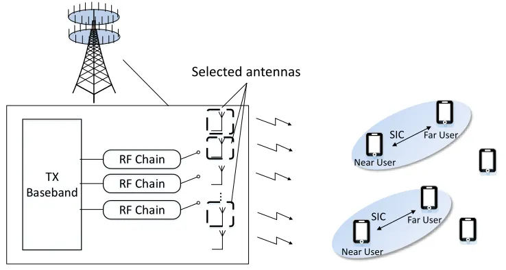
2.5 Illustration of antenna selection and user scheduling. . . 24
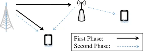
2.6 NOMA-based Relaying System with Single Relay. . . 36
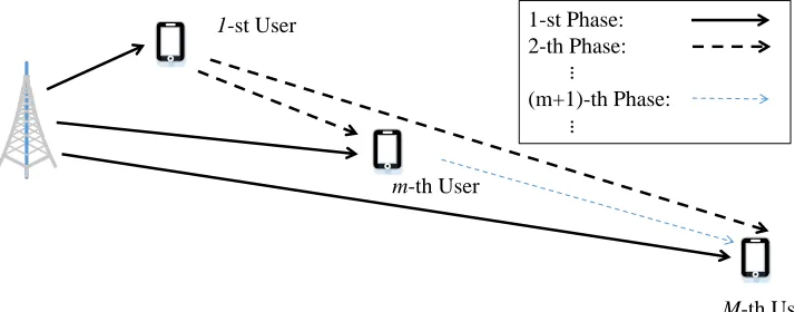
2.7 NOMA-assisted Relaying System with Multiple Relays. . . 37
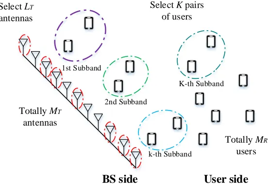
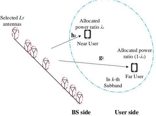
3.1 Massive MIMO-NOMA system with antenna selection and user scheduling. . . 43
3.2 User service ink-th subband of massive MIMO-NOMA system. . . 44
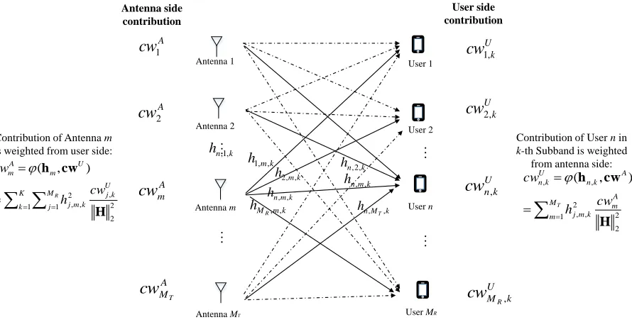
3.3 A contribution update example of joint AU contribution algorithm. . . 52
3.4 Sum rate and outage probability as functions of minimum required PSNR in single-band scenario whereMT =18, LT =6. . . 53
3.5 Sum rate and outage probability as functions of candidate antenna number in single-band scenario wheret =9,LT = 6. . . 54
3.6 Performance of sum rate and outage probability as functions of minimum re-quired PSNR in multi-band scenario whereMR = 10,LT =6, K =3. . . 56
3.7 Performance of sum rate and outage probability as functions of candidate user number in multi-band scenario wheret= 10,LT =6, K =3. . . 57
4.1 CNAR system model. . . 64
4.2 Decoding process at MT1 for the first phase based on SIC. . . 66
4.3 SIC-based decoding process at NOMA far user and near user for the second phase. . . 69
4.4 Illustration of conventional OMA system. . . 77
4.5 Depiction of OMA-based relaying system. . . 77
4.6 Performance of Outage probability as a function of target rateR0whenρ2= 15dB. 79 4.7 Outage probability as a function of BS transmit SNRρ1whenR0 =2. . . 79
4.8 Outage probability as a function of MT1 transmit SNRρ2whenR0 =2. . . 81
4.9 Single-user ergodic capacity as a function of MT1 transmit SNRρ2whenR0 = 2 andρ1= 19dB. . . 81
4.10 Sum ergodic capacity as a function of MT1 transmit SNRρ2 whenR0 = 2 and ρ1 =19dB. . . 82
4.1 Table for value of min{S NR2,1,S NR2,2}under different conditions . . . 76
4.2 A list for value of min{S NR3,1,S NR3,2}in different conditions . . . 76
Appendix A Proofs of Equations for Performance Analysis in CNAR System . . . 94 Appendix B Analysis of Complexity for single-band Scenario . . . 97
5G The 5-th Generation Network
AF Amplify-and-Forward
AWGN Additive White Gaussian Noise
BS Base Station
CNAR Collaborative NOMA Assisted Relaying System
D2D Device-to-Device
DF Decode-and-Forward
IoT Internet of Things
MIMO Multi-Input Multi-Output
mmWave millimeter-wave
MRC Maximal Ratio Combing
MT Mobile Terminal
MU-MIMO Multi-User Multi-Input Multi-Output
NOMA Non-orthogonal Multiple Access
OFDMA Orthogonal Frequency Division Multiple Access
OMA Orthogonal Multiple Access
PSNR Post-processing Signal-to-Noise Ratio
R-D Relay-Destination
RF Radio Frequency
S-R Source-Relay
SIC Successive Interference Cancellation
SU-MIMO Single-User Multi-Input Multi-Output
TDMA Time Division Multiple Access
Introduction
1.1
Background of 5G
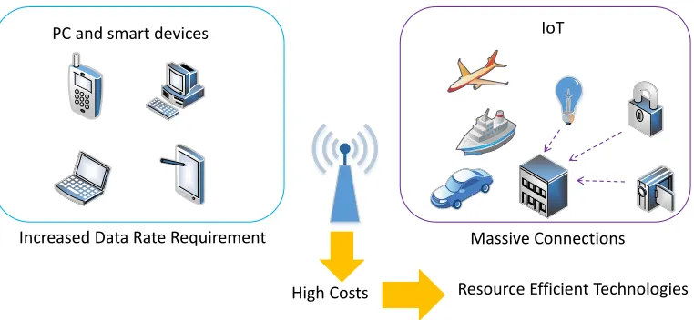
The future 5-th generation (5G) network is expected to provide high-performance
commu-nications for rapidly increased devices at anytime and anywhere [1]. On one hand, a large
number of smart devices, including smart phones, tablets and laptops for purposes of daily
work and entertainments, require remarkably higher data rate, along with enhanced cell-edge
rate [2]. The reason is according to [3], it is predicted that in 2020 the data traffic from
soft-ware downloading, social networking, web browsing, file sharing and multi-media streaming
will be significantly enhanced where the high-definition video traffic, with intensive
require-ments for data rate and real-time playing, is going to be 13 times over that in 2014. On the
other hand, the Internet of Things (IoT) [4] would make various sensors, wearable devices,
household appliance and even vehicles connected to the core network in order to establish the
”smart life” for personal health, economy and convenience. For industrial consideration, the
monitor center should connect to multiple machines and sensors with very low latency to
lect real-time information and control pipes, valves and grids [5]. The data volume associated
with each device in IoT don’t have to be very large since there are only simple data and control
message exchange. But a significant number of devices need to be connected simultaneously.
Consequently, the expected overall network capacity enhancement will be 1,000 folds over
current situation [6][7]. Compared to the extremely high requirements, the currently available
spectrum resource becomes quite limited.
The newly developed millimeter-wave (mmWave) frequency bands may potentially help
support the network traffic enhancement. Firstly, the short-distance line-of-sight (LOS)
direc-tional communications can be well supported by the 60 GHz mmWave band for very high data
rate [8]. Furthermore, it is possible to obtain larger channel bandwidth, around 500 MHz per
channel in mmWave compared to 5-20 MHz in mainstream microwave bands. Additionally,
the small wavelength facilitates installing massive antennas into the mmWave transceivers [9].
However, the drawbacks from mmWave remarkably undermine the potential performance
im-provement. The most critical point is that the signal in mmWave bands is highly sensitive to
blockages which lead to severe penetration [10]. This creates severe signal strength loss in
non-line-of-sight (NLOS) environments, very common in large-scale communication systems.
Moreover, practical hardware overhead further limits the application of mmWave technology.
For instance, the mixed signal components in mmWave transceivers bring higher costs and
en-ergy consumption than microwave transceivers [9]. Therefore, it is hard for mmWave spectral
resource to contribute significantly to serving massive users and increasing network capacity.
All the frequency bands in the currently available spectrum have almost been developed for
telecommunications in mainstream protocols. The bands for LTE-based communication [11]
Increased Data Rate Requirement Massive Connections
PC and smart devices IoT
High Costs Resource Efficient Technologies
Figure 1.1: 5G use cases and corresponding requirements.
still using some bands for transitions from 3G to 4G in some undeveloped areas. Moreover,
the 2.4 GHz frequency band has been widely used by Wi-Fi and Bluetooth protocols. As a
result, novel highly efficient communication techniques are in need of the hour for exploiting
the current resources.
1.2
Research Motivations
1.2.1
Advantages of Spectral and Power E
ffi
cient Technologies
Non-orthogonal multiple access (NOMA) is a 5G promising spectral efficiency technology
applicable in the current spectrum resource [13]. Conventional orthogonal multiple access
(OMA), e.g., time division multiple access (TDMA) [14] and orthogonal frequency division
multiple access (OFDMA) [15], allocates orthogonal resource blocks for different users to
avoid inter-user interference. Instead, NOMA introduces inter-user interference at the network
transmitted in one resource block where messages are allocated with different power levels.
When receiving the NOMA signal, certain user applies successive interference cancellation
(SIC) to remove the interference from other messages in order to obtain the message for its
own. Note that the power-domain multiplexing in NOMA allows a great number of messages
superposed into one signal. Hence, NOMA can increase the number of served users per cell.
And it is specially suitable for IoT where real-time connections between the control center and
massive various devices should be established without specific data rate requirements.
Massive Multi-input Multi-output (MIMO) is another spectral efficient technology for 5G
[16]. It can transmit multiple signals at the same time and frequency band by different spatial
patterns to multiple receivers. These signals can carry different data for a large group of users
or carry the same data for several specific users for performance gain. Additionally, with
beamforming technology to preprocess the signal at the transmitter side, the focus of the signal
can be narrowed to the targeted receiver so that the quality of the received signal is improved. In
this way, each cell can potentially support more users and increase the received signal strength.
Hence, the overall system capacity can be greatly enhanced within existing resources.
Relaying technology enables efficient utilization of power [17] to serve the increasing
cell-edge users. The better relay-destination (R-D) channel condition, which results from the short
R-D distance, leads to higher cell-edge user receive signal-to-noise ratio (SNR) than the direct
source-destination (S-D) transmission with the same transmit power. Moreover,
device-to-device (D2D) communication ability at smart device-to-devices enables some device-to-devices to be applied as
the relays [18], which saves the cost of deploying the relays. The relaying technology can also
enable the cooperation among cells if the relaying device is shared by several cells. Hence,
for all users [19].
1.2.2
Challenges for Resource Allocation
There are challenges to utilize NOMA, massive MIMO and relaying techniques and develop
relevant resource allocation strategies for overwhelming 5G system performance.
It is important to consider user scheduling and power allocation to cost-efficiently take
ad-vantage of NOMA protocol. Firstly, the dependence on SIC causes NOMA to be significantly
sensitive to channel quality. Due to channel condition variation, the non-orthogonality becomes
dynamic. Higher-level non-orthogonality leads to more contribution to improving system
per-formance, but with higher costs, i.e., higher requirements on SIC and worse stability. So to
control the level non-orthogonality, users should be scheduled into appropriate channels and
frequency bands. In particular, to seek a tradeoff between resource sharing and single-user
communication quality, the number of users sharing the same resource block and the relevant
user features should be decided. Note that NOMA protocol is not well applicable to certain
users associated with long distances, very poor channel conditions and very high target rates.
The reason is if allocating too much resources to satisfy these users’ requirements can cause
resource insufficiency for other users, which will downgrade the overall system performance.
Additionally, power level allocated to each message for the relevant NOMA user is supposed
to be well considered. This is because NOMA is a power-domain multiplexing strategy; the
power allocation influences the successful execution of SIC and whether single-user data rate
requirements will be met.
hardware and system complexity costs as well. The very large antenna array is partially
respon-sible for hardware costs. Moreover, for signal processing, each antenna needs to be connected
to a radio frequency (RF) chain, which introduces complicated hardware installation and
pro-cessing overhead. Furthermore, in the transitional stage from the 4-th generation network to
5G, the number of RF chains cannot match massive candidate antenna in the large array,
mak-ing it impractical to use all antennas in each time slot. Hence, selectmak-ing ”good” antennas to
match the existing RF chains exactly is a promising solution [20]. Moreover, each large-scale
antenna array has the upper-bound of capability to serve users; in certain time slot, serving
some users with extremely poor channel conditions will cost very much resource but obtain
only limited performance. So similarly, it is important to schedule ”good” users for
communi-cation in each time slot for cost-efficient resource utilization.
The relaying scheme should also be investigated to be adaptive to 5G in order to serve
multiple cell-interior and cell-edge users. Currently, a large number of smart devices have
been equipped with double antennas, and some of them can be applied as relaying devices to
enable D2D communications. Moreover, unlicensed band is going to be exploited in 5G [21].
The resource efficiency in conventional relaying systems are not high enough since the relaying
link requires one orthogonal resource block to avoid the interference. With extra unlicensed
band resource provided, the communication and resource efficiency can be possibly promoted.
Following these conditions, suitable relaying scheme for 5G with the idea of data offloading
[22] is worth considering. This is to improve the system throughput in order to guarantee the
quality of service for both the relaying devices (cell-interior users) and cell-edge users.
It is also inevitable to consider the integration of several 5G promising technologies. Firstly,
communication protocol [12] and rake receiver to counter the multipath fading are
revolution-ary technologies for highlighting the advancement of the 3G system over 2G. Then the 4G
breakthrough is featured by even more techniques, involving OFDMA protocol [15] to
im-prove the data rate, Voice over LTE (VoLTE) protocol [23] to transmit voice in pure data and
the true packet switched architecture to replace the circuit switched one. So 5G is expected
to be a revolution on communication system highlighted by multiple technologies.
Further-more, potentially compatible promising techniques for 5G are worth considering to improve
the system performance as much as possible. Moreover, some techniques are complementary
to each other. Massive MIMO is able to support multiple receivers or enhance the receive SNR
at certain receivers. NOMA can be applied to establish connections to a great number of users
simultaneously. The relaying technology can assist in transmitting signals to some users which
cannot have been supported by the BS. The features of these techniques create opportunities
for them to improve the performance for each other, contributing to better overall performance
in the 5G communication system.
Possible integration can be based on performance improvement of certain technology. The
drawback of NOMA is the communication quality for single user. In contrast to conventional
orthogonal multiple access (OMA) where the power in certain time slot [14] or frequency
band [15] is allocated to only one message, NOMA should allocate the same amount of power
to several messages, which undermines the single-user data rate. Hence, it is necessary for
NOMA to cooperate with other techniques for achieving better communication quality.
Mas-sive MIMO is able to provide received SNR gain by large-scale transmit antenna array. The
spectral efficiency of NOMA can be further developed by the relaying technology to support
mas-sive MIMO and relaying systems. Furthermore, to maximize the performance of these systems
within limited resources, it is important to consider relevant resource allocation strategies.
1.3
Research Objectives
Each research paper in the literature investigates only one promising technology in the future
5G on the preliminary implementation and performance. The objectives of this thesis are to
conduct integration of potential efficient techniques for 5G, i.e., massive MIMO, NOMA
pro-tocol, relaying technology, and, on the basis of systems formed by integrated techniques, to
propose resource allocation mechanisms in order to serve a great number of users
simultane-ously with high-level communication quality.
To exploit extremely high spectral efficiency for serving multiple users with good
com-munication quality for the 5G networks, the first objective is to integrate massive MIMO and
NOMA techniques into the 5G communication system. To take advantage of NOMA
pro-tocol, which is featured by power-domain multiplexing, to better the system performance, the
power allocation among NOMA users should also be specified in this designed massive-MIMO
NOMA system.
Next, in massive MIMO, limited RF chains make it impractical to use antenna all elements
in the MIMO antenna array; Additionally, the performance of NOMA protocol significantly
depends on channel conditions. Consequently, the following objective is to figure out antenna
selection and NOMA user scheduling algorithms to maximize user sum rate and control the
non-orthogonality between NOMA users prior to signal processing. In the massive
multiple-subband scenarios, respectively. Moreover, to make the algorithms executable in the
system, the trade-off between system performance and the computational complexity of the
algorithms should be achieved.
Furthermore, as the proliferation of 5G smart devices, a large number of which have the
re-laying ability and double antennas, causes more cell-edge users, it is important to use NOMA to
assist relaying systems to serve multiple cell-edge users. Thus, the next objective is to propose
the NOMA assisted relaying scheme based on the new features of smart devices and newly
developed unlicensed band resource to guarantee the single-user data rate. For achieving the
minimal outage probability for the best effect of data rate guarantee, the NOMA-related power
allocation scheme should be determined. For further system performance characterization and
evaluation for the power allocation scheme, the system ergodic capacity based on this power
allocation scheme needs to be analyzed.
1.4
Contributions
The main contributions of this thesis are listed as follows:
• A general review of advantages and relevant problems brought by NOMA, massive
MIMO and relaying techniques in 5G are provided. A literature survey is done for:
power allocation, user pairing, relaying scheme under NOMA protocol; antenna
selec-tion, user scheduling for MIMO system; performance analysis in NOMA-based relaying
system.
• A massive MIMO-NOMA system is designed to improve the communication quality
among NOMA users to maximize the sum rate is provided as the foundation for further
investigation.
• To achieve efficient resource allocation in massive MIMO-NOMA system, the antenna
selection and user scheduling mechanisms are investigated. According to different
sce-narios, the efficient antenna selection and user scheduling algorithms are proposed. In
single-band scenario, the antenna selection problem is solved by efficient search
algo-rithm, which achieves the search efficiency by limiting the candidate antennas into ones
beneficial to relevant users. For joint antenna selection and user scheduling in
multi-band multi-user scenario, joint AU contribution algorithm are raised by selecting the
antennas and users with the highest contribution to the total channel gain. Simulation
results demonstrate that proposed antenna selection algorithm achieves near-optimal
per-formance, and joint AU contribution algorithm achieves similar performance to existing
methods with reduced complexity. The proposed algorithms control the orthogonality
among NOMA users in a high-level without losing stability.
• A Collaborative NOMA Assisted Relaying (CNAR) system is proposed with the
collab-oration of S-R NOMA link as macro-cell communication and R-D NOMA link as
small-cell communication. The relay is executed in full-duplex way to improve the system
throughput. Moreover, the S-R and R-D phases are executed in licensed and unlicensed
band, respectively, to avoid the interference. Then with outage probability derived, the
power allocation ratios are obtained by minimizing the outage probability. Then
ca-pacity analysis in high SNR regime is also provided to further characterize the system
NOMA protocol. Simulation results validate our mathematical analysis, and show that
the relaying system assisted by NOMA achieves lower outage probability and higher
sum capacity than orthogonal multiple access (OMA). The proposed system develops
the spectral efficiency of NOMA protocol to serve multiple cell-edge users concurrently
with high data rate.
1.5
Thesis Outline
This outline of this thesis is as follows:
Chapter 2 investigates certain resource efficient technologies in 5G, i.e., NOMA, massive
MIMO, as well as relaying, their relevant problems and literature. Firstly, the critical points of
these technologies to achieve high resource efficiency are given. Then the problems brought
by these technologies are explained. The problem involves user scheduling, antenna selection,
power allocation and relaying mechanism design. Next, a study on the existing methods to
solve the problems is discussed.
Chapter 3 demonstrates the proposed methods to solve antenna selection and user
schedul-ing problems. The optimal power allocation scheme is provided for clarifyschedul-ing the standard of
antenna selection and user scheduling. Then efficient search algorithm is proposed to solve
antenna selection problem in single-band two user scenario. Next, Joint AU contribution
al-gorithm is proposed for joint antenna selection and user scheduling in multi-band multi-user
scenario. Simulation results are provided for validating the tradeoffbetween performance and
complexity of our proposed algorithms.
sys-tem model, the relaying mechanism assisted by NOMA is proposed. In the next section, to
characterize the system, outage probability analysis is given with mathematical insights, with
the help of which the optimal power allocation method is also proposed. Following this, the
sum capacity approximation is provided by analyzing the ergodic capacity for each user.
Sim-ulation results of the proposed mechanism are compared with the relaying scheme assisted by
conventional OMA.
Chapter 5 summarizes the ideas, analysis and results from this thesis and discusses the
Technologies for E
ffi
cient Utilization of
Resources in 5G
In this chapter, the technical aspect of the future 5G networks, following problems and the
relevant literature survey for existing solutions will be provided. The first section introduces
resource efficient technologies for the future 5G, i.e., NOMA, massive MIMO, relaying
mecha-nism, and describes their principles to achieve resource efficiency. Following this, the problems
brought by these technologies are discussed, which involves antenna selection, user scheduling,
power allocation and relaying scheme design. Lastly, the chapter provides currently available
algorithms and approaches for these problems.
2.1
Principles of Resource-E
ffi
cient technologies in 5G
The future 5G are confronted with an explosive device proliferation and greatly enhanced data
traffic. To satisfy these demands within relatively constrained resources and tolerably increased
costs, resource efficient strategies, involving NOMA, massive MIMO and the relaying
technol-ogy, is worth exploring.
2.1.1
NOMA
Drawbacks of Conventional OMA
Conventional OMA is able to service multiple users but some drawbacks downgrade the system
performance, one of which is serious interference management overhead at the network side.
To serve multiple users at the same time, the network side uses OMA protocol by dividing the
entire resource into orthogonal resource blocks in time-domain (TDMA) [14] or
frequency-domain (OFDMA) [15] to avoid inter-user interference. But if the constrained overall resource
is divided into multiple blocks for a great number of users, the resource volume per block
will be even more limited. The granularity of single resource block also has its lower bound.
Moreover, it is impractical if the network side undertakes all the interference management tasks
since the backhaul and feedback issues cost high overhead [24]. Thus, it would be better to
transfer some interference management tasks to the receiver side.
The other drawback for conventional OMA is the limitation on resource sharing. Whether
certain user reaches its target rate can be a standard for communication quality. For some
users with good channel conditions, the target rate can be easily reached so the resource can
be wasted to some extent. For users with poor channel conditions, we may need to allocate
an orthogonal block with large resource amount to guarantee the data rate [25][26], which
results in relatively low resource efficiency [27]. The phenomenon above will cause the overall
control center has to establish massive real-time connections to a variety of smart devices with
different channel conditions [7][28]. Hence, it’s a good strategy if certain users with good
channel conditions can share one resource block with ones with poor channel conditions.
NOMA Advantages over OMA and NOMA Principle
NOMA protocol is an advantageous strategy for user side interference management and
re-source sharing. NOMA allows several messages multiplexed at the same time and frequency.
At the transmitter side by superposition coding, several messages are superimposed with diff
er-ent allocated power level as a NOMA signal. Generally, more power is allocated to messages of
users with poorer channel conditions as the compensation, which also guarantees these users’
receive SNR in a comparable level to conventional OMA. At the receiver side, the users with
poor channel conditions treat the messages for other users and the environmental noise as the
whole noise for message decoding. The users with better channel conditions apply SIC for
message decoding. To be specific, they decode the messages for users with poorer channel
conditions in a similar manner. This decoding process is most likely successful due to better
channel conditions. Then the decoded messages are removed so that these uses are confronted
with less inter-user interference when they decode the messages for their own, which also
compensates for the less allocated power to these message. In other words, the general power
allocation idea achieves some user fairness, which can be further improved with accurate value.
Therefore, without considering the data rate with respect to each signal, we can support a
large number of users using NOMA, theoretically. The supporting ability is not restricted by
the number or the granularity of the resource blocks as it is in conventional OMA since NOMA
Time/Frequency
Pow
er
Time/Frequency
P
ow
er
User 1
User 2
User M
OMA NOMA
… …
…
Figure 2.1: Protocol difference between OMA and NOMA.
Decode
Decode
-𝑦 = 𝑃𝛼𝑀ℎs𝑀+ 𝑖=1 𝑖=𝑀−1
𝑃𝛼𝑖ℎs𝑖+ 𝑛
y
Noise
s𝑀 s𝑀
s𝑀−1 s𝑀−1
𝑃𝛼𝑀ℎs𝑀
Noise
Decode
-𝑃2𝛼2ℎs2
𝑃1𝛼1ℎs1+ 𝑛 Noise
s1 s1
Decode
-
s𝑚 s𝑚…
𝑃𝛼𝑀−1ℎs𝑀−1+ 𝑖=1 𝑖=𝑀−2
𝑃𝛼𝑖ℎs𝑖+ 𝑛
𝑃𝛼𝑚+1ℎs𝑚+1
Noise
𝑃𝛼𝑚ℎs𝑚+ 𝑖=1 𝑖=𝑚−1
𝑃𝛼𝑖ℎs𝑖+ 𝑛
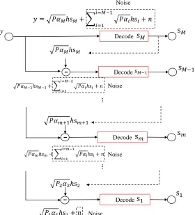
…
transmitter sends a NOMA signal superimposed by messages toMusers. The norms of channel coefficients from the transmitter to the 1-st, ..., m-th, ..., M-th receivers are ordered as |h1| >
... >|hm|> ... > |hM|. The superimposed NOMA signal is given by
x
=
P
(
√
α
1s
1+
...
+
√
α
ms
m+
...
+
√
α
Ms
M)
(2.1)where the power allocation ratios are ordered asα1 < ... < αm < ... < αM to compensate for
the poor channel conditions. The receive signal at them-th user becomes
y
=
P
|
h
m|
P
M i=1√
α
i+
n
m (2.2)The M-th user treat messages for other (M− 1) users and the environmental noise as the equivalent noise to decode the message for itself. So its post-processing SNR (PSNR) is given
by
S NR
M=
ρ|hM|2αM
ρ|hM|2PiM=1−1αi+1 (2.3)
For the m-th user, due to the ordered channel gains, it can most likely decode messages from (m+1)-th to M-th user successfully. Based on SIC, these messages are removed from the original NOMA signal received by them-th user. Then this user decodes its own message by treating the remaining messages and environmental noise as the equivalent noise, through
which the PSNR becomes
S NR
m=
ρ|hm|2α
m
ρ|hm|2Pmi=−11αi+1 (2.4)
in
S NR
1=
ρ
|
h
1|
2α
1.
(2.5)The above decoding process is illustrated in Fig. 2.2 for clearance.
NOMA Performance in Two-user Case
In many situations, there is minimum rate requirement for single user, for which only two user
share one resource block under NOMA protocol. In this typical case, users with better channel
conditions are denoted as near user (namely the 1-st user in the general case), while the other
as far users (namely the 2-nd user when M = 2 in the general case). For message decoding, far user considers the near user message and environmental noise as the whole noise to decode
the message for its own. According to the aforementioned power allocation idea, the power
allocated to the message for far user is much higher than it is for near user to compensate for
poor channel conditions. Next, near user uses SIC to decode and then remove the message for
far user, based on which it decode its own message with only the environmental noise as the
noise.
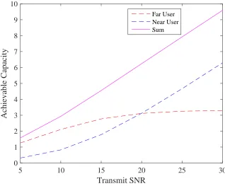
We firstly characterize NOMA performance in this simple two-user case. Fig. 2.3
demon-strates the achievable capacity as a function of transmit SNR. The power ratio allocated for
far user is 0.75 to compensate for the poorer channel condition. One can observe that for far
user, as transmit SNR increases, the achievable capacity gets close to a certain constant. This is
because far user treats the message for near user as part of the noise. When the transmit power
grows, the growth of noise power has similar level as that of useful signal power. In other
words, in Eq. (2.3) when M = 2, ρ → ∞ makesS NRM → αα2
5 10 15 20 25 30
Transmit SNR
0 1 2 3 4 5 6 7 8 9 10
Achievable Capacity
Far User Near User Sum
Figure 2.3: Achievable capacity under NOMA protocol.
capacity nearly grows linearly with transmit SNR. The reason is due to SIC, the noise for its
message decoding is only the environmental noise, the power of which doesn’t become larger
as transmit power increases. If we consider it in Eq. (2.5),S NR1 increase linearly withρ. In
this way, since the capacity for far user and near user both increase monotonically with transmit
SNR, the sum achievable capacity follows the same tendency.
Then we extend the above analysis to the general case where M users share one NOMA signal. For the 2-nd to the M-th user, as each of them need to consider other users’ messages as the noise, the achievable capacity is upper-bounded by certain constant. To be specific,
according to Eq. (2.4), as ρ → ∞, S NRm is asymptotically equivalent to Pmα−m1
i=1 αi, which is
1-st user, corresponding to the near user in Fig. 2.3, its lower allocated power ratio can be
compensated by the receive SNR which can increase unlimitedly. Therefore, NOMA protocol
takes advantage of the user with the best channel condition to increase the sum rate and ensures
good levels of achievable rate for other users.
2.1.2
Massive MIMO
Though the applicable spectrum is slight broaden by the unlicensed band in the future 5G, the
existing resource is still far from being sufficient for the expected 1,000 fold capacity increase.
The massive MIMO technology, developed from conventional MIMO, is a spectral efficient
strategy to improve the 5G system performance. It is featured by multiple transmitter antennas
and multiple receive antennas to enable multiple signal inputs and outputs so that the system
throughput is significantly enhanced. At the receiver side, there can be different forms, i.e., a
large receive antenna array corresponding to single-user multi-Input multi-Output (SU-MIMO)
and multiple devices equipped with single antenna corresponding to Multi-User Multi-Input
Multi-Output (MU-MIMO) [29].
For conventional MIMO, one reason to achieve spectral efficiency is the spatial domain
multiplexing. To be concrete, by multiple antennas, different signals are transmitted and
re-ceived in different spatial patterns at the same time and frequency band. The benefits from
spatial multiplexing can be considered in a system level and at the receiver. In a system level,
spatial multiplexing enables MIMO system to achieve a great degree of freedom gain with
desired channel conditions. For instance, in high SNR regime, the system capacity is
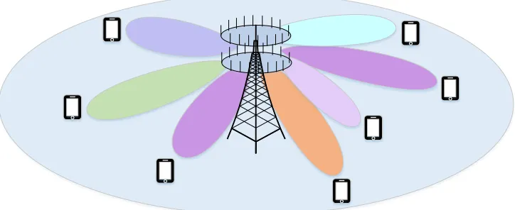
Figure 2.4: Depiction of massive MIMO system.
side can be the diversity gain [31], which results from the following situation. IfLRantennas at
user side receive the same signal from one transmit antenna, we receiveLR copies of the same
signal corresponding to LR different SNR levels. There are some mechanisms at the receiver
side to obtain the diversity gain. According to the Selection Combining [32], it’s easy to select
the maximum SNR from all the copies as the output SNR. However, the output can be further
improved if we make full use of all the LR copies. Hence, if we use receive-maximal ratio
combining (MRC) mechanism [33], the output SNR will be the summation of receive SNR at
all LR receive antennas. Similarly, from multiple transmit antennas sending the same signal,
the user device with single receive antenna can also take advantage all different transmission
paths to improve receive SNR if transmit-MRC mechanism is applied [34].
Another reason for high spectral efficiency in MIMO system is beamforming that signals
intended for a group of closely positioned users are modulated and transmitted in a specific
angel targeting at the user group to improve the transmission accuracy [35]. In other words, the
allocated power can be almost concentrated at that angle associated with targeted user group
Massive MIMO is also named as very large MIMO, full-dimension MIMO, hyper MIMO
and the large-scale antenna system. It reaps all the advantages from conventional MIMO but
on a very large scale by massive candidate antennas at the BS side and lots of receive
anten-nas at the user side [36]. Additional benefits can be obtained in massive MIMO. For instance,
from a great number of candidate antennas, it is more possible to find certain antennas with
ex-tremely good channel conditions, with which the transmit power is saved and system efficiency
is increased; the wireless network coverage can also be expanded to communicate with much
more users. Additionally, in MU-MIMO cases, massive transmit antennas at the BS contribute
to inter-user interference diminishment, which is achieved by the asymptotical orthogonality
among users if linear matched filter downlink precoding is applied at the BS side [37].
2.1.3
Relaying Technology
The relaying mechanism is widely used to improve the receive signal strength at cell-edge
users, which can be further exploited in 5G. Firstly, because of D2D connection ability in
smart devices, they can execute the relaying functions, which lower the load of the ISP without
having to establish additional infrastructure [7]. Furthermore, it is consistent with one of the
intentions by 5G, i.e., to shrink the cell size. Specifically, the size of macro cell can be shrunk
to the extent which exactly guarantees transmissions to relaying devices; one relaying device
is in charge of a small cell to improve the communication quality at users far from the BS.
Smaller cell size can increase the energy efficiency by short-range transmissions and easier
power concentration. Lastly, the newly developed high-frequency unlicensed band resource in
2.2
Challenges of Utilizing NOMA, MIMO and Relays
2.2.1
User Scheduling and Power Allocation in NOMA
In NOMA protocol, to guarantee the quality of service to each user, generally two users are
paired to share the same NOMA signal [38]. For both user to receive good-level service, it’s
worth considering which two users among all the users should be paired. Moreover, similar
to antenna side, in each time slot some users, if involved in communications, will get low
quality of service and cause low energy efficiency due to extremely poor channel conditions.
If they are forced paired with some users to execute NOMA protocol, they will affect normal
communications of other users; what’s more, the system performance, e.g., the sum rate, will
be even more downgraded. In this extreme case, those users will be given up temporarily for
cost-effective usage of system resources. This is fair since they can be scheduled in other time
slots when channel conditions are better [39].
With NOMA integrated into massive MIMO system, to improve the system performance, it
is important to select antennas and schedule users jointly as it is in conventional MIMO system
[40][41]. The reason is if we select antennas and users separately, e.g., select the antenna
subset first, some of the selected antenna may not be the best matches for users to be selected,
which may also influence user pairing strategy and performance. Hence, the joint selection of
antennas and users can lead to the best matched selected antennas and users.
Apart from user scheduling, power allocation is another step for NOMA system
perfor-mance improvement since NOMA is a power-domain multiplexing strategy. The objective of
power allocation can be maximization of sum rate or achieving the fairness with regard to data
TX Baseband
RF Chain
RF Chain
RF Chain
...
Selected antennas
SIC
SIC
Near User
Far User
Far User
Near User
Figure 2.5: Illustration of antenna selection and user scheduling.
2.2.2
Antenna Selection and User Scheduling in Massive MIMO
The efficiency and diversity gain in massive MIMO is obtained at the expense of very high
computational complexity and hardware cost. In particular, each antenna used for data
mission needs to be connected to one RF chain for signal processing. Each RF chain in
trans-mitter side consists of up-converter, power amplifier, filters and a digital-to-analog converter.
At the receiver side, each RF chain contains down-convertor, a low noise amplifier and
analog-to-digital convertor. Typical massive MIMO antenna array size can be 8×8, 16×16; it would
be even larger in the future [16]. Confronted with large number of users, if massive antennas
are all taken into use, the hardware costs will increase significantly. Potential problems will
be extended to system configuration and peripheral maintenance. Additionally, the increased
complexity of encoding and decoding spatial-time codes cannot be ignored. The above
prob-lems will impact real-time message transmission.
and costs. In each time slot, there are some antennas corresponding to better performance than
others. So the basic idea is to selectLT ”best” antennas from all MT candidate antennas based
on some criteria so that the number of required RF chains is kept as LT. Those unselected
antennas contribute moderately to system performance while cost extra complexity. Hence,
performance can still be maintained in high-level and hardware complexity can be reduced.
2.2.3
NOMA Assisted Relaying System Design
NOMA protocol can increase the efficiency of relaying mechanism. Conventional relay only
accepts single message input and output single message to cell-edge users. Instead, by
super-position coding, NOMA provides multiple inputs and multiple outputs for the relay. Moreover,
in the further 5G, smart device with D2D communication ability can be applied as a relay. With
NOMA assisted, the relay can decode the message from source NOMA signal for itself and
transmit the remaining part to multiple cell-edge users. This strategy saves the the deployment
of relays and improve the system spectral efficiency.
However, some technical issues are supposed to be specified for the NOMA assisted
ing system. To provide high throughput to support multiple users simultaneously, the
relay-ing scheme of the system need further investigation. Moreover, the power allocation method
among NOMA-based messages should be figured out to provide basic data rate guarantee for
2.3
Considerations on NOMA User Pairing
NOMA user pairing strategy can be investigated into two scenarios, based on fixed allocated
power and target rate guarantee, respectively. The scenario with fixed allocated power is less
complex since power ratios don’t need dynamically adjusting. For another scenario, user
pair-ing and real-time power allocation are jointly considered to satisfy the user target rate [43].
2.3.1
User Pairing with Fixed Allocated Power
In this case, we focus on the user pairing issue with predefined power ratios. Following the
assumptions in Eq. (2.1), we assume the m-th and the n-th user conditioned on m > n form a user pair with α2m +α2n = 1. Due to|hm|2 < |hn|2, based on NOMA principle, it holds that
αm> αn. So the achievable rate associated with these two users are
R
m=
log(1
+
αm|hm|2
αn|hm|2+1ρ
)
(2.6)and
R
n=
log(1
+
ρα
n|
h
n|
2)
.
(2.7)For the conventional OMA scheme, the achievable data rate associated withi-th user becomes
wherei∈ {m,n}. So the sum rate gain of NOMA over OMA scheme is given by
R
m+
R
n−
R
m−
R
n ρ→∞→
log(
1
α
n)
+
log(
ρα
n|
h
n|
2)
−
log(
ρ
|
h
m||
h
n|
)
=
log
|
h
m| −
log
|
h
n|
,
(2.9)
in very high SNR area. So more performance gain will be obtained if there is a lot difference
between the paired users’ channel gains.
2.3.2
User Pairing with Consideration of Target Rate
With the consideration of target rate, NOMA is executed under some condition. For some
user with weak connections to the transmitter in certain subband, satisfying the target rate
is the priority. If the transmit power is more than enough for that user to reach the target
rate, then the relevant subband can admit another user with strong connections to share the
power. Otherwise, the whole subband will be allocated to the weak user to compensate for
the poor channel quality as much as possible or we can schedule it in other time slot when its
corresponding channel conditions are better.
Following the assumption in Eq. (2.1) again, we focus on the m-th user as the one with poor connection in the relevant subband and we regard then-th user as the potential user to be admitted into the same subband. Assume the target rate isR0 = log(1+γ0) for them-th user,
then to satisfy the target rate, the following inequation should be met
αm|hm|2
This indicates that the maximal power allocation ratio ton-th user becomes
α
n=
0
,
for
|
h
m|
26
γ0 ρ
|hm|2− γ0
ρ
|hm|2(1+γ
0)
,
for
|
h
m|
2
>
γ0 ρ(2.11)
When|hm|2 6 γ0
ρ, it means the target rate for them-th user cannot even be reached. So a general pairing strategy is when|hm|2 > γρ0, the m-th user can be paired with then-th user. Otherwise,
we can consider allocate the entire power of relevant subband to them-th user or not schedule it for communication in the time slot since weak connection will reduce the energy efficiency.
Conditioned on the situation where the target rate for the m-th user can be reached, the performance gain of NOMA over allocating all power to them-th user is given by
R
m+
R
n−
R
e
m=
log(1
+
α
m|
h
m|
2α
n|
h
m|
2+
1ρ)
+
log(1
+
ρα
n|
h
n|
2)
−
log(1
+
ρ
|
h
m|
2)
=
log
1
+
ρα
n|
h
n|
21
+
ρα
n|
h
m|
2(2.12)
2.4
Considerations on NOMA Power Allocation
Since NOMA is a power-domain multiplexing strategy, power allocation strategy is extremely
important for the efficiency of using NOMA and user experience. User sum rate
maximiza-tion and fairness are mainstream objectives in optimizamaximiza-tion problems for resource allocamaximiza-tion
[44][45][46]. The problem formulations of these two objectives are provided as follows where
2.4.1
Sum Rate Maximization
Generally in sum rate maximization problems, one critical constraint is the data rate associated
with each user should meet the target rate as the communication quality guarantee. So the sum
rate maximization problem can be formulated as
max
α1,...,αMM
X
i=1
log(1
+
S NR
i)s
.
t
.
P
Mi=1
α
i=
1
0
6
α
i6
1
∀
i
,
i
∈ {
1
, ...,
M
}
S NR
i>
γ
0∀
i
,
i
∈ {
1
, ...,
M
}
(2.13)
whereS NRiis the PSNR at thei-th user.
2.4.2
Fairness Consideration
Although sum rate maximization leads to system performance maximization when the total
power is enough. However, due to higher data rate requirements or user proliferation, each
user can experience outage where the data rate doesn’t reach the target rate. Thus, user fairness
is worth considering for each user to experience as few outage events as possible, which can
be formulated as an outage probability minimization problem. Particularly, we define EventAj
happens when
ρ|hm|2αj ρ|hm|2Pij=−11αi+1
is satisfied [42]. To optimization problem to achieve user fairness can be formulated as
min
α1,...,αMmax
j
Pr[
A
j]s
.
t
.
P
Mi=1
α
i=
1
0
6
α
i6
1
(2.15)
2.5
Antenna Selection Algorithms
2.5.1
Antenna Selection and Use Scheduling Based on Exhaustive Search
Generally, higher channel norm leads to better massive MIMO system performance. To apply
channel norm as the criterion for antenna selection and user scheduling, one direct strategy
is to exhaustively search possible sub-matrix from the original complete matrix and select the
one corresponding to the maximal channel norm. The size of the sub-matrix is the number of
required antennas and users. But the computational complexity is extremely high due to direct
search of all possible combinations. The complexity can be reduced slightly in NBJTRAS
algorithm by transforming matrix computation to vector computation [47]. NBJTRAS involves
two stages, i.e., the operation on row and column dimension, of which the steps are given as
follows.
Suppose the complete channel matrix H ∈ CNR×NT. Note that each receive antenna in the
following algorithm can be considered as a single-antenna user device.
Stage 1: The Operation on Row Dimension Defineir ∈ {1,2, ..,CNLR
R}as the row
combina-tion index, which corresponds to their-th sub-matrixHir ∈ CLR×NT by lir = [l1ir l
2
ir ... l LR ir ]
this way, we obtainHir as
H
ir=
h
T l1 irh
T l2 ir...
h
T lLRir
=
H
irh
1
,
1
i
. . .
H
irh
1
,
N
Ti
H
irh
2
,
1
i
. . .
H
irh
2
,
N
Ti
...
. . .
...
H
irh
L
R,
1
i
. . .
H
irh
L
R,
N
Ti
(2.16)wherehT
x is thex-th row ofH. Then we definem x
ir to express the magnitude ofx-th column in Hir, which is given by
m
ixr
=
P
LRj=1
|
H
irh
j
,
x
i|
2
,
1
6
x
6
N
T
.
(2.17)Then we obtain the norm vectormT ir as
m
T ir=
[
m
1 ir
m
2 ir
...
m
NT
ir
]
.
(2.18)If we apply the evaluation mTi
r to all the C LR
NR possible combinations, we obtain the norm
matrixM∈CCLRNR×NT
expressed by
M
=
m
T 1m
T 2...
m
T CLR NR
=
m
11m
21...
m
NT1
m
12m
22...
m
NT2
...
... ... ...
m
1 CLR NRm
2 CLR NRStage 2: The Operation on Column Dimension We find the largestLT elements in ther-th
row ofMand attain the summation of them, denoted asmir
max. At the same time, we record the
column indices of theseLTelements in the defined index vectorlic(ir)=[l
1
ic(ir)l
2
ic(ir)...l LT ic (ir)]
T
.
This then yields the max-norm vector
m
Tmax=
[
m
1maxm
2max...
m
C LR NRmax
]
.
(2.20)Then we find
i
r=
arg max
16ir6CLR NR
m
irmax (2.21)
Finally, the indices of selected receive and transmit antennas are recorded inli
r andlic(ir),
re-spectively, according to which we obtain the subset channel matrixHsubas the optimal solution.
The complexity of NBJTRAS algorithm is analyzed for further comparison to other
al-gorithms. For Stage 1, in each Hir, the summation of elements in each column requires LR
computational operations. To deal with NT columns for eachHir matrix and C LR
NR matrices in
total, it needs LRNTCLRN
R operations. For Stage 2, there areC LR
NR rows in matrixMand we need
to find the largest LT elements from NT elements per row with summing these elements up.
Then the maximal element should be found fromCLR
NR in vectorm T
max. SoC
LR
NR(NT +LT)+C LR NR
operations are needed for Stage 2. Eventually, by ignoring factors with low magnitudes, the
2.5.2
Antenna Selection and Use Scheduling Based on Successive
Elimi-nation
Another strategy of antenna selection and user scheduling is to successively remove the
anten-nas and users who generate the least contribution to system performance. This strategy can
be regarded as a sub-optimal algorithm. The complexity is gradually reduced as antennas and
users are eliminated one after another. JASUS Algorithm [48] elaborates this strategy in this
way. It successively deletes the antenna which undermines performance the most in each
iter-ation. In the mean time, it chooses the group of users generating a great level of orthogonality
during each iteration, which is elaborated by SUS Algorithm nested in JASUS Algorithm. The
steps of JASUS and SUS are provided as follows. The target is to selectN antennas out of M
candidate antennas and scheduleK users out ofXcandidate users in each time slot.
Algorithm 1Steps of JASUS
1: initializeA ← {1, ...,M},t ←1;
2: whilet6(M−N)domaxRate←0;
3: for eachminAdo
4: Ut ←a set ofK users using SUS(A\{m},K);
5: R−m= Rsum(A\{m},Ut);
6: if R−m >maxRatethen
7: maxRate←R−m;
8: mbad ←m;
9: U ← Ut;
10: end if
11: end for
12: A ← A\{mbad};
13: t ←t+1;
14: end while
15: The set of antenna is given byAand the set of user is given byU;
Here, we also analyze the complexity of JASUS algorithm. Note that due to multiple
Algorithm 2Steps of the semi-orthogonal user selection function (SUS)
1: initializeU ← {1, ...,X},i←1,SU ← ∅
2: whilei<(X−K)do
3: for each xinU do
4: gx,A = hx,A−P i−1
j=1
hx,Aeg
H jegj
||egj|| 2 ;
5: end for
6: iopt = argmaxx∈U||gx,A||2;
7: SU∪ SU{iopt};
8: U ← U\SU;
9: egi = giopt;
10: i← i+1;
11: end while
12: Output the set of user is given byU;
from different perspectives. But the orders match the time consumption of the simulation
executed in Chapter 3. Hence, we provide one perspective of estimating the complexity as the
representative. For eacht from JASUS algorithm, the main computational operations are on Step 3 5 where the operation times arei(M−t)(X−i) for eachifrom the while loop in Step 2. Considering the number of loops, the key operation times in SUS algithm are PK−1
i=1 i(M −
t)(X−i)= (M−t)[(K−21)KX−(K−1)K6(2K−1)]. Back to JASUS algorithm, for eachtwithin one while loop in Step 2, the main operation times are (M−t)PK−1
i=1 i(M−t)(X−i). Since there are totally
(M−N) loops, the whole operations arePM−N
t=1 (M−t)
PK−1
i=1 i(M−t)(X−i). By concentrating
on factors with high magnitude, the complexity is obtained asK2(M−N)MX.
2.6
Current Designs for NOMA-based Relaying System
There are two existing ideas of deploying the relaying devices. One way is to apply a relay
terminal for signal strength enhancement for single far user. The other way is to apply multiple
They are described as follows.
2.6.1
System with Single Relay
The system is proposed by authors in [49]. In this system, there are two users in one cell where
one user has weak connections to the BS due to long distance. So one relay is introduced to
enhance the signal strength for far user. The transmission is executed in two phases:
First Phase: The BS transmits a NOMA signal superimposed by two messages. The relay
only decodes the message for far user. The near user decodes the message for far user first,
then it uses SIC to decode the message for its own.
Second Phase: The BS transmit the single message to near user. The relay transmits single
message to far user. far user will receive its own message, but near user will receive two
messages. Since based on SIC, near user removes the message for far user again and decodes
the message for its own.
Therefore, the capacity for the near user is
C
1=
12log(1
+
γ
1(
t
1))
+
12log(1
+
γ
1(
t
2))
(2.22)whereγ1(t1) is the PSNR obtained at near user in the first phase, andγ1(t2) is the PSNR obtained
in the second phase. And the capacity for the far user is given by