Improved Performance Incremental Conductance Pv
Mppt Technique
Mr. BANOTH RAJA has received M.Tech degree in Electrical Power System in BOMMA Institute of Technology and Science in 2016. He received Bachelor of technology Degree in Electrical and Electronics Engineering from BOMMA Institute of Technology and Science in 2014 and his field of interest includes power systems, FACTS devices and Renewable Energy Sources.
Email id: [email protected]
Mr. GUGULOTH RAMESH has Received M.Tech degree in Electrical Power System from HIMT, Affiliated to JNTU Hyderabad. He received Bachelor of technology Degree in Electrical and Electronics Engineering from J.B Institute of Engineering and Technology, Affiliated to JNTU Hyderabad in 2011 and his field of interest includes power systems, FACTS devices and Renewable Energy Sources.
Email: [email protected]
Mr. DHARAVATH UPENDER NAIK has Received M.Tech degree from BOMMA INSTITUTE OF TECHONOLGY AND SCIENCE, 2014 Received B.Tech degree from MADHIRA INSTITUTE OF TECHNOLOGY AND SCIENCE, 2007 and Working as faculty from 2010 to till now.
Email: [email protected]
Abstract: Variable-step incremental conductance (Inc.Cond.) system, for photovoltaic (PV) maximum power point tracking, has benefits of good tracking precision and
quick meeting speed. However, it needs
straightforwardness in its execution because of mathematical division calculations engaged with its calculation structure. Moreover, conventional variable step-estimate, based on division of PV module power change by PV voltage change, experiences steady state power motions and dynamic issues particularly under sudden ecological changes. In this investigation, an improvement is acquainted with Inc.Cond. Calculation keeping in mind goal to completely wipe out division
I. INTRODUCTION
The advanced industrial society, populace development, and the interest in the natural issues have enormously expanded the need of new and clean renewable energy sources [1]. Among the last mentioned, photovoltaic (PV) solar energy has progressed toward becoming these days a genuine promising renewable/exchange energy source because of its few points of interest, for example, nonattendance of noise or mechanical moving parts, low operation cost, no outflow of CO2 or other unsafe gasses, adaptability in size, and its accommodation with remain solitary systems notwithstanding grid-associated ones where they can be introduced near load focuses, sparing transmission lines losses [2, 3].
In spite of the fact that PV energy has as of
late gotten extensive consideration, high
establishment cost and low transformation
effectiveness of PV systems set a trouble against its utilization on an expansive scale [4]. Moreover, the non-linear conduct and reliance of PV panels on the barometrical temperature and irradiance level make one of the main difficulties confronting the PV division's penetration to the energy advertise [5]. To limit these downsides, PV operation at the maximum power point is a need which thusly augments the PV system productivity. Different maximum power point tracking (MPPT) strategies have been exhibited in writing [6– 9]. They vary in the tracking exactness, union speed, and dynamic reaction under sudden natural changes, required sensors, equipment usage, and reliance on PV module parameters.
The most regularly utilized MPPT calculations are Perturb and Observe (P&O) and incremental conductance (Inc.Cond.) techniques [10]. P&O calculation is broadly utilized as a part of PV remain solitary systems for its basic usage [11– 14]. In these PV systems, MPPT calculations are ideally acknowledged utilizing minimal effort microcontrollers keeping in mind the end goal to chop down the whole system cost. In this way, the P&O, being a number juggling division calculation, is a helpful decision to be executed by these controllers. Inc.Cond. is more mind boggling in structure than P&O as it restrains numerous
mathematical divisions which increment
computational weight [15].
In any case, with respect to these strategies execution, P&O can without much of a stretch prompt incorrect judgment and wavering around the maximum power point (MPP) which results in power misfortune [16]. Subsequently, Inc.Cond. system is a superior competitor particularly amid quickly shifting natural conditions. This is on account of, when contrasted and P&O strategy, Inc.Cond. can precisely track the MPP, with less steady-state motions and quicker reaction amid changes in this way expanding the tracking proficiency [17– 21].
Also, numerous adjustments have been acquainted with settled advance size utilized as a part of the Inc.Cond. strategy to transform it to a variable one that gets littler towards the MPP [22– 28]. The last enhances the system execution and unravels the exchange off between tracking precision and meeting speed. In any case, conventional variable advance size, naturally balanced by the PV power change concerning PV voltage change (ΔP/ΔV ), can influence the MPPT execution because of the deviation of this progression measure, especially under sudden changes [29, 30].
This paper goes for consolidating the benefits of basic calculation structure with high system execution amid transients in one MPPT procedure. Subsequently, a changed Inc.Cond. Calculation is proposed highlighting full disposal of the division computations in this way, improving the calculation structure. Moreover, a variable advance size is proposed which just relies upon the PV power change (ΔP), along these lines dispensing with its division by the PV voltage change (ΔV). The proposed step-size can limit power motions around the MPP and adequately enhance the MPPT dynamics amid sudden changes. This will bring about a total sans division variable-advance strategy which does not just have the benefits of improved steady-state and transient execution yet additionally has straightforward calculation usage. This lessens the handling constant, empowering the calculation to be actualized by minimal effort microcontrollers which thusly decreases system costs.
test results, which confirm the prevalence of the proposed method over the conventional one, are shown in the fourth area, separately. At last, a conclusion is displayed in the eighth segment.
II. PV system under investigation
The considered PV system comprises of a PV module, a DC– DC boost converter and a battery load as appeared in Fig. 1a.
2.1 PV mathematical model
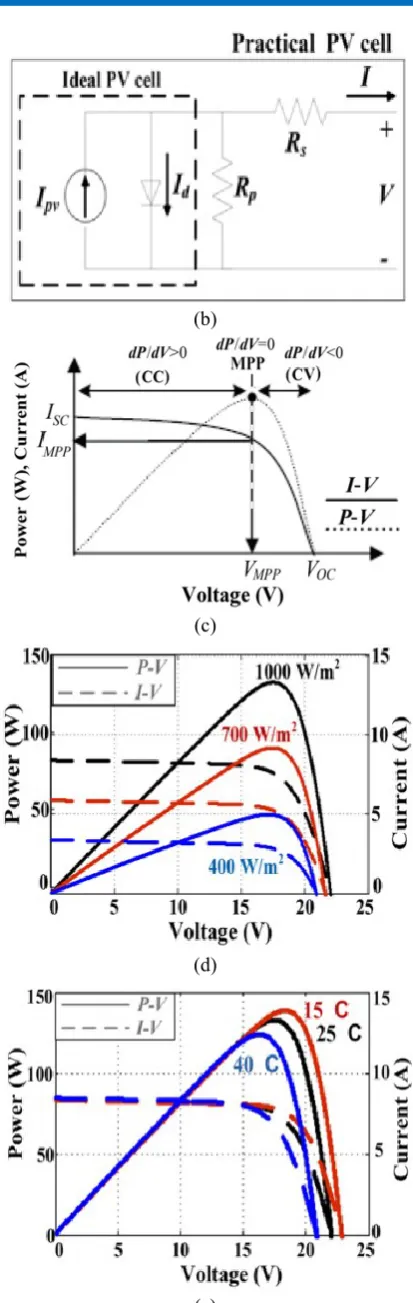
A pragmatic PV gadget can be spoken to by a light-produced current source and a diode out and out with internal shunt and series protections as appeared in Fig. 1b. A PV module is made out of a few PV cells and the perception of the qualities at its terminals results in communicating its output current by the accompanying condition [31],
Where, V and I are the PV output voltage and current separately. Ipv is the PV current which is created by the episode light (specifically relative to the sun irradiance) and Io is the saturation current of the PV module. an is the diode ideality constant and Rs, Rp are the internal series and parallel protections of the module individually. At long last, Vt is the PV warm voltage with Ns PV cells associated in series. Vt equivalents to Ns.k.T/q where; q is the electron charge (1.60217646 × 10⁻¹⁹ C), k is Boltzmann constant (1.3806503 × 10⁻²³ J/°K), and T (in ˚K) is the temperature of the p– n intersection.
(a)
(b)
(c)
(d)
(e)
(b) PV cell single diode model.
(c) I–V and P–V characteristics at given conditions, I-V, P–V curves of KD135SX_UPU PV module. (d) Under three irradiance levels at 25˚C.
(e) For three different cell temperatures at irradiance of 1000 W/m2.
2.2 Boost converter
The design of boost converter, shown in Fig. 1, can be summarized as follows [32]
Where V is the PV output voltage, Vbattery is the battery load voltage and D is the duty ratio determined by the applied MPPT algorithm to directly control the boost chopper switching. ΔiL is the change in inductor current, L is the chopper inductor and fsw is the chopper switching frequency.
2.3 MPPT
Condition (1) demonstrates that a PV module has non-linear I– V attributes that rely upon the irradiance level and PV cells temperature. Fig. 1c demonstrates the I– V and P– V bends of a PV module, at a given cell temperature and irradiance level, on which it's striking that the PV panel has an ideal working point, the MPP. In the locale left to the MPP, the PV current is practically constant and the PV module can be approximated as a constant current source. Then again, appropriate to the MPP, the PV current starts a sharp decline and the PV module can be approximated as a constant voltage (CV) source. The PV module trademark bends differ with the changing irradiance level and cell temperature [5], as appeared in Figs. 1d and e. The PV module cut off is linearly subject to the irradiance level dissimilar to the open-circuit voltage which practically free of it. Then again, PV cell temperature essentially influences the open-circuit voltage esteem though it negligibly affects the cut off esteem.
As the PV module trademark bend shifts with changing irradiance or cell temperature, the MPP moves. Subsequently, persistent tracking to the MPP winds up plainly required to amplify the PV system productivity. The last is accomplished
utilizing a MPPT calculation which decides the suitable duty ratio (D) that controls the switching of the DC– DC converter put between the PV module and the load to guarantee that the PV panel maximum power is separated. An effective MPPT bargains between the tracking pace and steady-state precision and shows quick reaction amid sudden natural changes. As indicated by these criteria, the Inc.Cond. Method can be considered as a suitable competitor [17– 21].
III Conventional variable-step Inc.Cond. Technique
The structure of the conventional variable-step Inc.Cond. Procedure can be outlined in the accompanying two areas;
3.1 Conventional Inc.Cond. Algorithm
Inc.Cond. technique is based on the slope of the PV module P–V curve [6] where
Since
Then
current builds (diminishes), the MPP moves to one side (left) regarding PV voltage. To make up for this development, the MPPT must build (diminish) the PV module's working voltage.
At the point when contrasted and other straightforward, ease MPPT calculations as P&O [12], the main preferred standpoint of Inc.Cond. Calculation is that it can decide the exact bearing to come to the MPP along these lines diminishing the steady-state motions and enhancing system reaction under quickly changing conditions [16– 21]. Be that as it may, with respect to calculation structure, conventional Inc.Cond. Calculation incorporates various division estimations and a moderately complex basic leadership process which thus raises the need of an all the more powerful microcontroller including higher clock frequency, bigger memory and skimming point computation capacity, diminishing the likelihood of accomplishing a minimal effort system arrangement [15].
3.2 Conventional variable step-size
For a settled step Inc.Cond. Calculation, a littler step-size backs off the MPPT while a bigger one builds the steady-state motions around the MPP. An answer for this clashing circumstance is to have a variable step-size that gets littler towards the MPP keeping in mind the end goal to adjust the contending points of joining pace and tracking exactness. The conventional variable step-size relies upon the PV power change partitioned by the PV voltage change (ΔP/ΔV) [23]. For an immediate control conspire which specifically controls the converter switching without outer control circles, the considered step is the adjustment in the converter duty ratio (ΔD) as appeared in (11).
Where,
and N1 is the scaling factor tuned at the design stage to adjust the conventional step-size (ΔD) to compromise between tracking accuracy and its convergence speed.
(a)
Fig. 2: Inc. Cond. algorithm flowchart (a) conventional (b) Proposed.
IV Proposed variable-step Inc.Cond. technique
An upgrade is presented in the structure of the conventional Inc.Cond. calculation to dispense with all its division calculations and disentangle its usage. Additionally, the conventional variable step is adjusted to enhance its execution. The proposed step size is utilized by the proposed sans division Inc.Cond. calculation to straightforwardly control the converter switching.
4.1 Proposed division-free Inc.Cond. algorithm
A change is acquainted with the Inc.Cond. calculation with a specific end goal to kill all the division calculations in the calculation. Utilizing (8)– (10), the accompanying adjustments can be executed
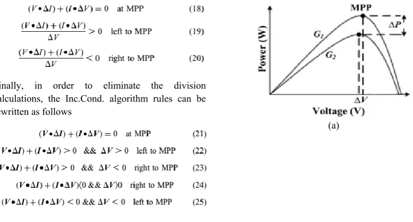
Binding together the denominators in (15)– (17) to V(ΔV), this denominator can be dispensed with from the primary condition as it is adjusted to zero while just V is killed from the denominator of the other two conditions as it is constantly positive and its sign won't influence these conditions. In this way, controlling (18)– (20) results in
Finally, in order to eliminate the division calculations, the Inc.Cond. algorithm rules can be rewritten as follows
The flowchart of the proposed calculation is given in Fig. 2b where the expulsion of all the division calculations in the calculation is remunerated by
applying number-crunching/logic mathematical
operations. Hence, calculation structure
unpredictability is limited which thus diminishes handling continuous and empowers the calculation to be executed by ease microcontrollers.
4.2 Proposed variable step-size
The conventional step-size displayed in (11), being dependant on the difference in the PV power concerning PV voltage change, shows dynamic execution deterioration amid sudden irradiance changes. Further, steady-state power motions remarkably emerge around the MPP. This can be clarified as takes after.
4.2.1 During stable environmental conditions: On account of unavoidable factors as estimation blunder, swells and noise, the condition that (ΔI/ΔV ) and (−I/V) to be precisely equivalent could never be fulfilled. Along these lines, the working point would not settle precisely at the MPP. Rather, it sways around the MPP, changing the indication of the augmentation after each ΔP estimation [19, 20]. It is clear, from Fig. 3a, that in the locales near the MPP and appropriate to it (CV area), the change in PV voltage (ΔV) is too little bringing about vast ΔP/ΔV steps. Despite the fact that, these vast step-sizes increment the tracking speed at begins of PV operation, they can amplify the steady-state power motions influencing the PV system exactness which thus diminishes the calculation productivity.
(b)
(c)
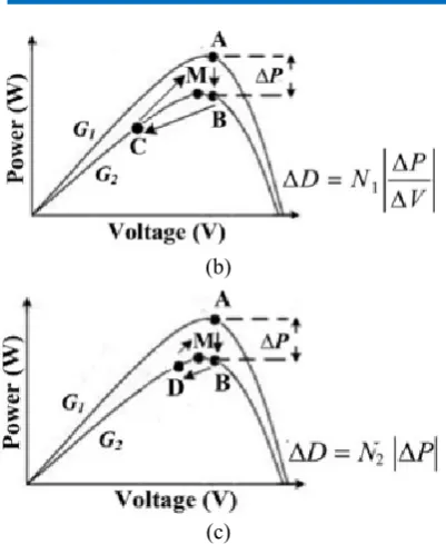
Fig. 3: Effect of irradiance change on MPP
(a) Peak PV power shift, MPPT performance adopting.
(b) Conventional ΔP/ΔV based variable step. (c) Proposed ΔP based variable step.
4.2.2 During varying irradiance conditions: The conventional variable step may indicate poor transient execution amid sudden irradiance changes. As appeared in Fig. 3a, when the irradiance changes from G1 to G2, there is an extensive power change (ΔP) while the PV voltage change (ΔV) is moderately too little. Since the step-size relies upon ΔP/ΔV, this will bring about an expansive converter duty ratio change (ΔD) in this way moving the working point far from the new MPP. Striking transient lessening in the PV power happens and the calculation sets aside longer opportunity to come to the new MPP. Therefore, the transient power misfortune will increment, diminishing the tracking proficiency.
To beat the last mentioned, this paper proposes a variable step-size which depends just on the PV power change (ΔP). The proposed step size is utilized by the MPPT calculation to specifically control the converter switching, consequently it speak to the adjustment in the converter duty ratio as appeared in (26)
Where, N2 is the scaling factor which is tuned at the design stage to adjust the proposed step-size to
compromise between the tracking accuracy and its convergence speed.
It is detectable, from the PV module P– V bend, that the change in PV power (ΔP) is little around the MPP and expansive far from it. Subsequently, the step-size, which relies upon ΔP, will be substantial far from the MPP and abatements around the MPP to trade off between the steady-state power motions and the tracking speed. Not at all like the conventional variable step which relies upon two undulated parameters (ΔP and ΔV) and their division, the proposed variable step depends just on ΔP. Expelling the division by ΔV, from the step-size, adds more disentanglement to the calculation and wipes out extensive step-size varieties that happen at little PV voltage changes. Despite the fact that this may back off the tracking procedure at the beginning of operation, it limits the steady-state motions around the MPP consequently enhancing the tracking exactness and effectiveness. Besides, this decreases the move of the working point far from the MPP amid sudden irradiance changes which results in better transient execution with quick dynamic reaction and less transient power misfortune.
For advance clarification, an illustrative case is appeared in Fig. 3b and c. At the point when the irradiance diminishes from G1 to G2, the working point shifts from 'A' to 'B', bringing about an impressive ΔP because of PV current change (ΔI) while ΔV is very nearly zero. To come to the new MPP 'M', the MPPT calculation must decrement the duty ratio D. Subsequently, the calculation execution is influenced by the variable step received to accomplish this decrement. For the conventional ΔP/ΔV subordinate step, the very nearly zero ΔV will bring about a huge step-size that limitlessly decrements D and move the operation to point 'C'. Thus, an eminent transient power misfortune happens and the calculation sets aside long opportunity to come to the new MPP 'M'. For the proposed ΔP based step, the vast step-size is maintained a strategic distance from and D is decremented to move the working point to 'D' which is near the MPP 'M'. This will secure the tracking procedure and decrease transient power misfortune.
V Simulation work
conventional ΔP/ΔV subordinate variable step-size with that of the proposed without division Inc.Cond. Strategy receiving the proposed ΔP based variable step-size. This is performed under two step changes in irradiance levels (from 1000 to 400 W/m2 at 0.2 s at that point from 400 to 700 W/m2 at 0.4 s.), at 25 °C. A KD135SX_UPU PV module is used with particulars given in Appendix. Also, the connected DC– DC boost converter parameters are given as takes after:
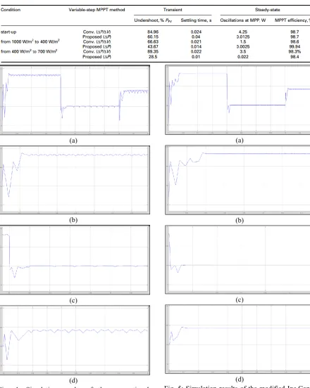
Chopper inductance (L): 2.3 mH, Switching frequency (fsw): 15 kHz and Vbattery = 3 × 12 V. Figs. 4 and 5 demonstrate the execution of the conventional strategy and that of the proposed one individually amid the considered step changes in irradiance while Table 1 gives their steady-state and transient execution parameters. It can be inferred that; under shifting irradiance conditions, the two systems can successfully track the PV maximum power yet with various levels of tracking precision, speed and transient undershoot.
Figs. 4a– d demonstrate transient and steady state execution of the conventional technique at start-up, first and second irradiance step changes individually. The last is rehashed for the proposed procedure as appeared in Figs. 5a– d. It is recognizable, that the disposal of the division by ΔV in the proposed step-size has restricted the substantial increment in the step consequently limiting the steady-state motions around the MPP on the punishment of slower tracking speed toward the start of PV system operation. Be that as it may, amid sudden irradiance changes, the proposed variable step gives better transient execution and quicker reaction.
Considering Table 1, the MPP tracking time, gained by the proposed procedure, is lessened by 33.3% and by 54.55% of that accomplished by the conventional method at the first and the second step changes separately. Moreover, the proposed step prevailing with regards to decreasing the power undershoot by right around 24.8%, 23% and 60.85% of the maximum followed PV power at 1000 W/m2, 400 W/m2 and 700 W/m2 individually. At long last,
the negligible steady-state power motions,
experienced by the proposed procedure, improve its MPPT proficiency when contrasted and that of the conventional method. Tracking effectiveness can be
characterized as the rate ratio of the followed PV power by the considered MPPT calculation at certain natural conditions to the pinnacle PV power under same conditions.
For advance confirmation of the
predominance of proposed system under changes, the two methods are retested at settled irradiance of 1000 W/m2 under two step changes in temperature (from 25°C to 40°C at 0.2s then from 40°C to 15°C at 0.4s).
Figs. 7 and 8 demonstrate the execution of the conventional method and that of the proposed one separately amid the considered step changes in temperature while Table 2 gives their steady-state and transient execution parameters. It can be
reasoned that; under changing temperature
conditions, the two systems can successfully track the PV maximum power yet with various levels of tracking exactness, speed and transient undershoot.
Figs. 6a– d indicate transient and steady state execution of the conventional technique at start-up, first and second temperature step changes separately. The last is rehashed for the proposed system as appeared in Figs. 7a– d. It is recognizable, that the disposal of the division by ΔV in the proposed step-size has restricted the vast increment in the step consequently limiting the steady-state motions around the MPP on the punishment of slower tracking speed toward the start of PV system operation. Be that as it may, amid sudden temperature changes, the proposed step gives better transient execution and quicker reaction.
Considering Table 2, the MPP tracking time, obtained by the proposed procedure, is lessened by 81.25% and by 36.67% of that accomplished by the conventional method at the first and the second step changes separately. Besides, the proposed step prevailing with regards to diminishing the power undershoot by just about 25.4%, 97% and 23.87% of the maximum followed PV power at 25 °C, 40 °C and 15 °C individually. At long last, the negligible steady-state power motions, experienced by the proposed system, improve its MPPT productivity when contrasted and that of the conventional procedure. Unmistakably the proposed system applies less steady-state power motions around the MPP of each P– V bend in respect to every irradiance level.
(a)
(b)
(c)
(d)
Fig. 4: Simulation results of the conventional Inc.Cond. method adopting the conventional ΔP/ ΔV based variable step under varying irradiance: a Overall PV power with zoom at
b Start-up
c First step change d Second step change.
(a)
(b)
(c)
(d)
Fig. 5: Simulation results of the modified Inc.Cond. method adopting the proposed ΔP based variable step under varying irradiance:
a Overall PV power with zoom at b Start-up
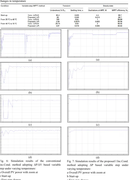
Table 2: Simulation performance indicators of the conventional and proposed techniques under two step changes in temperature
(a)
(b)
(c)
(d)
Fig. 6: Simulation results of the conventional Inc.Cond. method adopting ΔP/ΔV based variable step under varying temperature:
a Overall PV power with zoom at b Start-up
c First step change d Second step change.
(a)
(b)
(c)
(d)
Fig. 7: Simulation results of the proposed l Inc.Cond. method adopting ΔP based variable step under varying temperature:
a Overall PV power with zoom at b Start-up
Henceforth, simulation results demonstrate that the proposed strategy's steady-state and transient exhibitions exceed those of the conventional one, inferable from its connected ΔP-based variable step-size, yet with easier usage due the whole division figurings end from its calculation structure. This is done under sudden irradiance changes and in addition under sudden temperature changes which thus confirms the viability and prevalence of the proposed variable-step Inc.Cond. Procedure under various ecological changes.
VI Conclusion
In this paper, an ease variable-step MPPT strategy is proposed based on Inc.Cond. Calculation. The altered calculation includes full end of the included division calculations, which rearranges its structure and lessens the required genuine preparing time, in this way encouraging calculation execution by minimal effort micro controllers with a specific end goal to chop down system costs. Besides, the proposed related variable step, being exclusively subject to PV power change, indicates insignificant steady-state power motions around the MPP notwithstanding improved transient execution under sudden changes. The adequacy of the proposed system is confirmed by simulation and trial results.
References
1 Bose, B.K.: ‘Global energy scenario and impact of power electronics in 21st century’, IEEE Trans. Ind.
Electron., 2013, 60, (7), pp. 2638–2651.
2 Guerrero, J.M., Blaabjerg, F., Zhelev, T., et al.: ‘Distributed generation: toward a new energy paradigm’, IEEE Ind. Electron. Mag., 2010, 4, (1), pp. 52–64.
3 Hosenuzzaman, M., Rahim, N.A., Selvaraj, J., et al.: ‘Global prospects, progress, policies, and environmental impact of solar photovoltaic power generation’, Renew. Sustain. Energy Rev., 2015, 47, (41), pp. 284–297.
4 Liserre, M., Sauter, T., Hung, J.Y.: ‘Future energy systems: integrating renewable energy sources into the smart power grid through industrial electronics’, IEEE Ind. Electron. Mag., 2010, 4, (1), pp. 18–37.
5 Hohm, D.P., Ropp, M.E.: ‘Comparative study of maximum power point tracking algorithms’, Prog. Photovolt., Res. Appl., 2003, 11, (1), pp. 47–62. 6 Jain, S., Agarwal, V.: ‘Comparison of the performance of maximum power point tracking schemes applied to single-stage grid-connected photovoltaic systems’, IET Electr. Power Appl., 2007, 1, (5), pp. 753–762.
7 Esram, T., Chapman, P.L.: ‘Comparison of photovoltaic array maximum power point tracking techniques’, IEEE Trans. Energy Convers., 2007, 22, (2), pp. 439–449.
8 Subudhi, B., Pradhan, R.: ‘A Comparative study on maximum power point tracking techniques for photovoltaic power systems’, IEEE Trans. Sustain. Energy, 2013, 4, (1), pp. 89–98.
9 Gomes de Brito, M.A., Galotto Jr., L., Sampaio, L.P., et al.: ‘Evaluation of the main MPPT techniques for photovoltaic applications’, IEEE Trans. Ind. Electron., 2013, 60, (3), pp. 1156–1167. 10 Sera, D., Mathe, L., Kerekes, T., et al.: ‘ On the perturb-and-observe and incremental conductance MPPT methods for PV systems’, IEEE J. Photovolt., 2013, 3, (3), pp. 1070–1078.
11 Pacheco, V.M., Freitas, L.C., Vieira Jr., J.B., et al.: ‘Stand-alone photovoltaic energy storage system with maximum power point tracking’. Proc. IEEE Applied Power Electronics Conf. (APEC), 2003, pp. 97–102.
12 Ingegnoli, A., Iannopollo, A.: ‘A maximum power point tracking algorithm for stand-alone
photovoltaic systems controlled by low
computational power devices. Proc. IEEE
Mediterranean Electro Technical Conf.
(MELECON), 2010, pp. 1522–1527.
13 Aghazadeh, H., Kojabadi, H.M., Yazdankhah, A.S.: ‘Stand-alone PV generation system with maximum power point tracking’. Proc. Environment and Electrical Engineering Conf., 2010, pp. 549–552. 14 Elgendy, M.A., Zahawi, B., Atkinson, D.J.: ‘Assessment of perturb and observe MPPT algorithm implementation techniques for PV pumping applications’, IEEE Trans. Sustain. Energy, 2012, 3, (1), pp. 21–33.
15 Faranda, R., Leva, S.: ‘Energy comparison of MPPT techniques for PV systems’, WSEAS Trans. Power Syst., 2008, 3, (6), pp. 446–455.
photovoltaic system’. Proc. IEEE Electrical and Control Engineering Conf. (ICECE), September 2011, pp. 5792–5795.
17 Azevedo, G.M.S., Cavalcanti, M.C., Oliveira, K.C., et al.: ‘Evaluation of maximum power point tracking methods for grid connected photovoltaic systems’. Proc. IEEE Power Electronics Specialists Conf., 2008, pp. 1456–1462.
18 Spiazzi, G., Buso, S., Mattavelli, P., et al.: ‘Low complexity MPPT techniques for PV module converters’. Proc. IEEE Power Electronics Conf., June 2010, pp. 2074–2081.
19 Zhang, X., Zha, L., Liu, F., et al.: ‘The analysis of power loss caused by the truncation error of MPPT algorithms’. IEEE Symp. on Power Electronics for Distributed Generation Systems (PEDG), June 2010, pp. 7–11.
20 Adly, M., Ibrahim, M., El Sherif, H.: ‘Comparative study of improved energy generation maximization techniques for photovoltaic systems’. Proc. IEEE Asia-Pacific Power and Energy Engineering Conf. (APPEEC), March 2012, pp. 1–5. 21 Sekhar, P.C., Mishra, S.: ‘Takagi–Sugeno fuzzy-based incremental conductance algorithm for maximum power point tracking of a photovoltaic generating system’, IET Renew. Power Gener., 2014, 8, (8), pp. 900–914.
22 Liu, B., Duan, S., Liu, F., et al.: ‘Analysis and improvement of maximum power point tracking algorithm based on incremental conductance method for photovoltaic array’. Proc. IEEE Power Electronics and Drive Systems Conf., 2007, pp. 637– 641.
23 Liu, F., Duan, S., Liu, F., et al.: ‘A variable step size INC MPPT method for PV systems’, IEEE Trans. Ind. Electron., 2008, 55, (7), pp. 2622–2628. 24 Menniti, D., Burgio, A., Sorrentino, N., et al.: ‘An incremental conductance method with variable step size for MPPT: Design and implementation’. Proc. Electrical Power Quality and Utilization Conf. (EPQU), September 2009, pp. 1–5.
25 Mei, Q., Shan, M., Liu, L., et al.: ‘A novel improved variable step-size incremental-resistance MPPT method for PV systems’, IEEE Trans. Ind. Electron., 2011, 58, (6), pp. 2427–2434.
26 Elgendy, M.A., Zahawi, B., Atkinson, D.J.: ‘Assessment of the incremental conductance maximum power point tracking algorithm’, IEEE Trans. Sustain. Energy, 2013, 4, (1), pp. 108–117.
27 Faraji, R., Rouholamini, A., Naji, H.R., et al.: ‘FPGA-based real time incremental conductance maximum power point tracking controller for photovoltaic systems’, IET Power Electron., 2014, 7, (5), pp. 1294–1304.
28 Soon, T.K., Mekhilef, S.: ‘A fast-converging MPPT technique for photovoltaic system under fast-varying solar irradiation and load resistance’, IEEE Trans. Ind. Inf., 2015, 11, (1), pp. 176–186.
29 Ridge, A.N., Amaratunga, G.A.J.: ‘Photovoltaic maximum power point tracking for mobile applications’, Electron. Lett., 2010, 46, (22), pp. 1520–1521.
30 Ping, W., Hui, D., Changyu, D., et al.: ‘An improved MPPT algorithm based on traditional incremental conductance method’. Proc. IEEE Power Electronics Systems and Applications Conf. (PESA), June 2011.