Statcom Control Of Solar Farm As Pv-Statcom And Inverterbased Wind
Farm For Increasing Power Transmissionlimits Using Lcl Filters With
Fuzzy Control
Ravindar Moodu
1,Ramavath Shankar Naik
2,Gera Ratna Kumari
31Assistant Professor with the Department of Electrical&Electronic Engineering at SLC College, JNT University, Hyderabad,
Telangana, India. [email protected] .
2Assistant Professor with the Department of Electrica l&Electronic Engineering at SLC College, JNT University, Hyderabad,
Telangana, India. [email protected]
3Assistant Professor with the Department of Electrical & Electronic Engineering at SLC College, JNT University,
Hyderabad, Telangana, India, E-mail [email protected]
Abstract- This paper presents a novel concept of utilizing a photovoltaic (PV) solar farm inverter as STATCOM, called PV-STATCOM,Fuzzy control for improving stable power transfer limits of the interconnected transmission system. The entire inverter rating of the PV solar farm, which remains dormant during nighttime, is utilized with voltage and damping controls to enhance stable power transmission limits. During daytime, the inverter capacity left after real power production is used to accomplish the aforementioned objective. Transient stability studies are conducted on a realistic single machine infinite bus power system having a midpoint located PV-STATCOM using EMTDC/PSCAD simulation software. The PV-STATCOM improves the stable transmission limits substantially in the night and in the day even while generating large amounts of real power. Power transfer increases are also demonstrated in the same power system for: 1) two solar farms operating as PV-STATCOMs and fuzzy 2) a solar farm as PV-STATCOM and an inverter-based wind farm with similar STATCOM controls. This novel utilization of a PV solar farm asset can thus improve power transmission limits which would have otherwise required expensive additional equipment, such as series/shunt capacitors
or separate flexible ac transmission system controllers
.
Index Terms—Damping control, flexible ac
transmissionsystems(FACTS), inverter, photovoltaic solar power systems, reactive power fuzzy control, STATCOM, transmission
capacity ,voltage control,wind power system.
I. INTRODUCTION
F LEXIBLE AC transmission sy are being increasingly considered to increase the avail- stem (FACTS)controllers able power transfer limits/capacity (ATC) of existing transmission lines [1]–[4], globally. New research has
been reported on
the nighttime usage of a photovoltaic (PV) solar farm (when
it is normally dormant) where a PV solar farm is utilized
as aSTATCOM–a FACTS controller, for performing voltage con trol, thereby improving system performance
and increasing grid
connectivity of neighboring wind farms [5], [6]. New voltagecontrol has also been proposed on a PV solar farm to act as aSTATCOM for improving the power transmission capacity[7].Although, [8] and [9] have proposed voltage-control functionality with PV systems,
none have utilized the PV system for
power transfer limit improvement. A full converter-based windturbine generator has recently been provided with FACTS capabilities for improved response during faults and fault ridethrough capabilities [10].This paper proposes novel voltage control, together withauxiliary damping control, for a grid-connected PV solar farminverter to act as a STATCOM both during night and dayfor increasing transient stability and consequently the powertransmission limit. This technology of utilizing a PV solar farmas a STATCOM is called “PV-STATCOM.” It utilizes the entiresolar farm inverter capacity in the night and the remainder
inverter capacity after real power generation during the day,both of which remain unused in conventional solar farm operation. Similar STATCOM control functionality can also beimplemented in inverter-based wind turbine
generators during
no-wind or partial wind scenarios for improving the transientstability of the system. Studies are performed for two variantsof a single-machine infinite bus (SMIB)
system. One SMIB
system uses only a single PV solar farm as PV-STATCOMconnected at the midpoint whereas the other system uses acombination of a PV-STATCOM and
distributed generator (DG) withsimilar STATCOM functionality. Three-phase fault studiesare conducted using the electromagnetic transient software, and the improvement in the stable powertransmission limit is investigated for different combinations ofSTATCOM controllers on the solar and wind farm inverters,both during night and day.Section II describes the study systems. The results for variousfault studies are presented
in Section III. The performances
of different proposed controls during daytime and nighttimeare presented. The implications of implementing this newPV-STATCOM technology on large-scale solar systems aredescribed in Section IV, while the conclusions
are presented in
Section IV.
II. SYSTEM MODELS
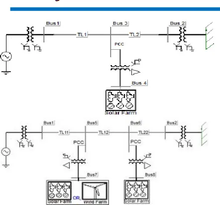
The single-line diagrams of two study systems: Study System 1 and Study System 2 are depicted in Fig. 1(a) and (b),respectively. Both systems are single-machine infinite bus(SMIB) systems where a large equivalent synchronous generator (1110 MVA) supplies power to the infinite bus
over a
200-km, 400-kV transmission line. This line length is typical ofa long line carrying bulk power in Ontario. In Study System 1, a100-MW PV solar farm (DG) as STATCOM (PV-STATCOM)is connected at the midpoint
of the transmission line. In Study
System 2, two 100-MVA inverter-based distributed generators(DGs) are connected at 1/3 (bus 5) and 2/3 (bus 6) of the linelength from the synchronous generator. The
DG connected at
bus 6 is a PV-STATCOM and the other DG at bus 5 is eithera PV-STATCOM or a wind farm with STATCOM functionality. In this case, the wind farm employs permanent-magnetsynchronous generator (PMSG)-based wind turbine generators with a full ac-dc-ac converter. It is
understood that the solar DG
and wind DG employ several inverters. However, for this analysis, each DG is considered to have a single equivalent inverterwith the rating equal to the total rating of solar DG or windDG, respectively. The wind DG and
solar DG are considered
to be of the same rating, hence, they can be interchanged interms of location depending upon the studies being performed.Fig. 2 presents the block diagrams of various
subsystems of two
equivalent DGs. All of the system parameters aregiven in
[1].A. System Model
The synchronous generator is represented by a detailed sixthorder model and a DC1A-type exciter [1]. The transmission-linesegments TL1, TL2, TL11, TL12, and
TL22, shown in Fig. 1,
are represented by lumped pi-circuits. The PV solar DG, asshown in Fig. 2, is modeled as an equivalent voltage-source inverter along with a controlled current voltage-source as
the dc source
which follows the - characteristics of PV panels [11]. Thewind DG is likewise modeled as an equivalent voltage-sourceinverter. In the solar DG, dc power is provided by the solarpanels, whereas in the full-converter-based wind DG, dc powercomes out of a controlled ac–dc
rectifier connected to the PMSG
wind turbines, depicted as “wind Turbine-Generator-Rectifier(T-G-R).” The dc power produced by each DG is fed into thedc bus of the corresponding inverter, as
illustrated in Fig. 2. A
maximum power point tracking (MPPT) algorithm based on anincremental conductance algorithm [12] is used to operate thesolar DGs at its maximum power point all of the time and is integrated with the inverter controller [11].
The wind DG is also
assumed to operate at its maximum power point, since this proposed control utilizes only the inverter capacity left after themaximum power point operation of the solar DG
and wind DG.
For PV-STATCOM operation during nighttime, the solarpanels are disconnected from the inverter and a small amountof real power is drawn from the grid to charge the dc capacitor.The voltage-source inverter in each DG is composed of six insulated-gate bipolar transistors (IGBTs)
and associated snubber
circuits as shown in Fig. 2. An appropriately large dc capacitorof size 200 Farad is selected to reduce the dc side ripple [13].Each phase has a pair of IGBT devices which converts the dcvoltage into a series of variable-width
pulsating voltages, using
Fig. 1. Single-line diagram of (a) study system I with a single solar farm (DG)and (b) study system II with a solar farm (DG) and a solar/wind
farm (DG). B. Control System
1) Conventional Reactive Power Control: The conventionalreactive power control only regulates the reactive power outputof the inverter such that it can perform unity power factor operation along with dc-link
voltage control [15]. The switching
signals for the inverter switching are generated through two current control loops in - -0 coordinate system [15], [16]. Theinverter operates in a conventional controller mode only provided that “Switch-2” is in the “OFF” position. In this simulation, the voltage vector is aligned with the quadrature axis,that is, 0 [15], [16], hence, is only proportional towhich sets the reference for the upper control loop involving PI1. Meanwhile, the quadrature axis component isused for dc-link voltage control through
two PI controllers (PI-2
and PI-3) [14], [16] shown in Fig. 2(b) according to the setpointvoltage provided by the MPPT and and injects all available real power “P” to the network [15]. To generate
the proper IGBT
switching signals (gt1, gt2, gt3, gt4, gt5, gt6), the – components ( and ) of the modulating signal are converted intothree-phase sinusoidal modulating signals and compared with ahigh-frequency (5-kHz) fixed magnitude
triangular wave or carrier signal.
2) PCC Voltage Control: In the PCC voltage control
mode ofoperation, the PCC voltage is controlled through reactive powerexchange between the DG inverter and the grid. The conventional “ ” control channel is replaced by the PCC voltage controller in Fig. 2(b), simply by
switching “Switch-1” to the position “A.” Hence, the measured signal at the PCC is compared with the preset reference value and is passedthrough the PI regulator,
PI-4, to generate .
The rest of the controller remains unchanged. The upper current control loop is used to regulate the PCC voltage whereasthe lower current control loop is used for dc voltage control and
Fig. 2. Complete DG (solar/wind) system model with a damping
controller and PCC voltage-control system.
as well as for the supply of DG power to the grid. The amountof reactive power flow from the inverter to the grid depends onsetpoint voltage at the PCC. The parameters of the PCC voltagecontroller are tuned by a systematic
trial-and-error method to
achieve the fastest step response, least settling time, and a maximum overshoot of 10%–15%. The parameters of all
controllersare given in the Appendix.
3) Damping Control: A novel auxiliary damping controller
is added to the PV control system and shown in Fig. 2. (b). Thiscontroller utilizes line current magnitude as the control signal.The output of this controller is added with the signal . Thetransfer function of this damping controller
is expressed as in
[19](1)The transfer function is comprised of a gain, a washout stage,and a first-order lead-lag compensator block. This controller isutilized to damp the rotor-mode
oscillations of the synchronous
generator and thereby improve system transient stability. Thedamping controller is activated by toggling “Switch-2” to the“ON” position. This damping controller can operate in conjunction with either the conventional reactive power
control mode
At first, the base-case generator operating power level is selected for performing the damping control design studies. Thispower level is considered equal to the transient stability limitof the system with the solar farm being disconnected at night.At this operating power level,
if a three-phase fault occurs at
Bus 1, the generator power oscillations decay with a dampingratio of 5%. The solar farm is now connected and operated inthe PV-STATCOM mode. The parameters of the damping controller are selected as follows. The
washout time constant
is chosen to allow the generator electromechanical oscillations in the frequency range up to 2 Hz to pass through [19].The gain , time constants , and are sequentially tunedto obtain the fastest settling time of the electromechanical oscillations at the base-case generator
power level through repetitive
PSCAD/EMTDC simulations. Thus, the best combination of thecontroller parameters is obtained with a systematic hit-and-trialtechnique, and the parameters are given in the
Appendix. It is
emphasized that these controller parameters are not optimal andbetter parameters could be obtained by following more rigorouscontrol-design techniques [19],
[20]. However, the objective of
this paper is only to demonstrate a new concept of using a PVsolar farm inverter as a STATCOM using these reasonably goodcontroller parameters. In this controller, although the line current magnitude signal is used, other
local or remote signals,
which reflect the generator rotor-mode oscillations [1],
may alsobe utilized.
III. SYSTEM STUDIES
Transient stability studies are carried out using simulation software, for both the study systems duringnight and day, by applying a three-line-to-ground (3LG) faultat bus 1 for five cycles. The damping ratio is used to express the rate of decay of the amplitude of oscillation [20]. For anoscillatory mode having an eigenvalue of , the
dampingratio is defined as
(2)where is the time constant.
FACTS
Flexible AC Transmission Systems, called FACTS, got in
the recent years a well known term for higher controllability in power systems by means of power electronic devices. Several FACTS-devices have been introduced for various applications worldwide. A number of new types of devices are in the stage of being introduced in practice.In most of the applications the controllability is used to avoid cost intensive or landscape requiring extensions of
power systems, for instance like upgrades or additions of substations and power lines. FACTS-devices provide a better adaptation to varying operational conditions and improve the usage of existing installations. The basic applications of FACTS-devices are:
• Power flow control,
• Increase of transmission capability, • Voltage control,
• Reactive power compensation, • Stability improvement, • Power quality improvement, • Power conditioning, • Flicker mitigation,
• Interconnection of renewable and distributed generation and storages.
TABLEI
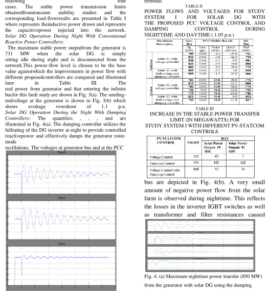
POWER FLOWS AND VOLTAGES FOR STUDY SYSTEM I FOR SOLAR DG WITHCONVENTIONAL REACTIVE POWER CONTROL AND PROPOSED DAMPINGCONTROL BOTH DURING NIGHTTIME AND DAYTIME ( 1.05 p.u.)
Therefore, for a 5% damping ratio of the rotor mode havingan oscillation frequency of 0.95 Hz, as considered in this study,the postfault clearance settling time of the
oscillations to come
within 5% (typically within 3 times the time constant) of itssteady-state value [1], [20] is almost 10 s. The peak overshootof PCC voltage should also be limited within 1.1 p.u. of nominal voltage. The maximum stable generator
power limit for the
system is determined through transient stability studies for different modes of operation of the solar DG in study system 1, andthose of the solar DG and the solar/winds
DGs in study system 2.
A. Case Study 1: Power Transfer Limits in Study System 1 1) Conventional Reactive Power Control With Novel Damping Control:
aredisconnected, and the solar DG inverter is connected to thegrid using appropriate controllers, as will be described. Powertransmission limits are now determined for the
following four
cases. The stable power transmission limits
obtainedfromtransient stability studies and the corresponding load-flowresults are presented in Table I where represents theinductive power drawn and represents the capacitivepower injected into the network.
Solar DG Operation During Night With Conventional Reactive Power Controllers:
The maximum stable power outputfrom the generator is
731 MW when the solar DG is simply
sitting idle during night and is disconnected from the network.This power-flow level is chosen to be the base value againstwhich the improvements in power flow with different proposedcontrollers are compared and illustrated
later in Table III. The
real power from generator and that entering the infinite busfor this fault study are shown in Fig. 3(a). The sending-endvoltage at the generator is shown in Fig. 3(b) which
shows avoltage overshoot of 1.1 p.u.
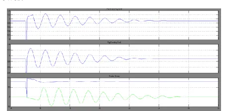
Solar DG Operation During the Night With Damping Controllers: The quantities , , , and are illustrated in Fig. 4(a). The damping controller utilizes the fullrating of the DG inverter at night to provide controlled reactivepower and effectively damps the generator rotor-mode
oscillations. The voltages at generator bus and at the PCC
Fig. 3. (a) Maximum nighttime power transfer (731 MW)
from the generator
when solar DG remains idle. (b) Voltage at the generator terminal.
TABLE-II
POWER FLOWS AND VOLTAGES FOR STUDY
SYSTEM I FOR SOLAR DG WITH
THE PROPOSED PCC VOLTAGE CONTROL AND
DAMPING CONTROL DURING
NIGHTTIME AND DAYTIME ( 1.05 p.u.)
TABLE III
INCREASE IN THE STABLE POWER TRANSFER LIMIT (IN MEGAWATTS) FOR
STUDY SYSTEM I WITH DIFFERENT PV-STATCOM CONTROLS
bus are depicted in Fig. 4(b). A very small
amount of negative power flow from the solar
farm is observed during nighttime. This reflects
the losses in the inverter IGBT switches as well
as transformer and filter resistances caused
Fig. 4. (a) Maximum nighttime power transfer (850 MW)
controller. (b) Voltages at the generator terminal and DG
PCC.
by the flow of real current from the grid into the solar farm inverter to charge the dc-link capacitor and maintain its voltage constant while operating the PV inverter as STATCOM with the damping controller (or even with a voltage controller). During nighttime, the reference dc-link voltage is chosen around the typical daytime-rated maximum powerpoint (MPP) voltage.
The oscillations in the solar PV power output during nighttime, as seen in Fig. 4, are due to the active power exchanged by the solar inverter both during the charge and discharge cycles in trying to maintain a constant voltage across the dc-link capacitor, thereby enabling the inverter to operate as a STATCOM.
Solar DG Operation During the Day With a Conventional Reactive Power Controller : The conventional control of a PV solar DG does not seem to alter the stable transmission limit in any appreciable manner.
Solar DG Operatio n During the Day With a Damping Controller : The quantities Pg,, Pinf, Psolar and Qsolar are
shown for the cases without the damping controller and with the damping controller in Figs. 5 and 6, respectively. The available inverter capacity after real power generation of 91 MW is 41.5 MVAr, which is used for damping oscillations during the day. The power transfer capacity increase in the daytime is expected to be lower than the nighttime, since only a part of the total inverter capacity is available for damping control during the day. However, it is noticed from Table I that the maximum power transfer during night time (850 MW) is actually less than the maximum power transfer value during the daytime (861 MW). This is because of an additional constraint that while increasing the power transfer, the overshoot in PCC voltage should not exceed 1.1 p.u. If the power transfer is allowed until its damping ratio limit of 5% regardless of voltage overshoot, the maximum nighttime power transfer is observed to be 964 MW whereas the maximum daytime power transfer is expectedly seen to be lower at 940 MW (plots not shown).
Fig. 5. Maximum daytime power transfer (719 MW) from
the generator with solar DG generating 91-MW real
power.
Fig. 6. Maximum daytime power transfer (861 MW) from
the generator with solar DG generating 91-MW real power
and using the damping controller.
2 ) PCC Voltage Control With the Novel Damping Control : Transient stability results for a new control strategy involving PCC voltage control, together with damping control, are shown in Table II for the following four cases.
Solar DG Operation During the Night With a Voltage Controller : The increase in the power transfer limit depends upon the choice of reference values for PCC voltage . In the best scenario when is regulated to 1.01 p.u., the maximum power output from the generator increases to 833 MW, compared to 731 MW when the solar DG operates with conventional reactive power control.
production, the ability to change the bus voltage is limited, which leads to a lower increase in power transmission capacity.
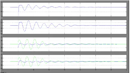
Fig.
7. (a) Maximum nighttime power transfer (899 MW) from
the generator while the solar DG uses a damping
controller with voltage control and (b) voltages at the
generator terminal and solar DG PCC (1.01 p.u.).
Solar DG Operation During the Night With Both Voltage and Damping Controllers:
The generator and infinite bus power are depicted in Fig. 7(a), and corresponding voltages are shown in Fig. 7(b). Although, the rotor-mode oscillations settle faster, the power transfer cannot be improved beyond 899 MW due to high overshoot in voltages.
Solar DG Operation During the Day With voltage and Damping Controllers :
A further increase in power transfer is observed when both voltage control and damping control are employed, compared to case 2) when only the voltage controller is utilized. For Study System 1, the net increase in power transfer capability as achieved with different PV-STATCOM controls in comparison with that obtained from conventional reactive power control of the solar DG, is summarized in Table III. The maximum increase in the power transfer limit during nighttime is achieved with a combination of voltage control and damping control, whereas the same during daytime is accomplished with damping control alone.
This is because at night, the entire megavolt-ampere rating of the solar DG inverter is available for reactive power exchange, which can be utilized for achieving the appropriate voltage profile at PCC conducive for increasing the power transfer, as well as for
increasing the damping of oscillations. During daytime, first, the generation of real power from the solar DG tends to increase the voltage at PCC [5] and second, the net reactive power availability also gets reduced especially with large solar real power outputs. Therefore, it becomes difficult with limited reactive power to accomplish the appropriate voltage profile at PCC for maximum power transfer and to impart adequate damping to the oscillations. However, if only damping control is exercised during daytime, power transfer
TABLE IV
POWER FLOWS AND VOLTAGES FOR STUDY
SYSTEM II FOR BOTH SOLAR DG AND WIND DG
WITH CONVENTIONAL REACTIVE POWER
CONTROL AND PROPOSED DAMPING CONTROL
BOTH DURING NIGHTTIME AND DAYTIME ( 1.05
p.u.)
limits appear to improve with higher real power outputs
from the solar DG. This is because real power generation
increases the PCC voltage which can be potentially helpful
in increasing the power transfer capacity. Since damping
control is found to be more effective during the daytime,
B . Case Study 2 : Power Transfer Limits in Study System II
In this study, the proposed damping control strategy is compared with the conventional reactive power control strategy for Study System II shown in Fig. 1(b). A three-phase-to-ground fault of 5 cycles is applied to the generator bus at 8 s. The power transfer limits obtained through transient stability studies for different cases are illustrated in Table IV. The following eight cases are studied:
1 ) Night time:
Case1 – None of the DGs Generate Real Power : The maximum power transfer limit is 731 MW as in Table I. Case2– Only Wind DG Generates Real Power. Both DGs Operate With Conventional Reactive Power Control : The power transfer limit decreases slightly with increasing wind power output.
Case3 – None of the DGs Generate Real Power But Both DGs Operate With Damping Control : The different variables, generator power , infinite bus power , real power of wind DG , reactive power of the wind DG , real power of the solar DG , and the reactive power of the solar DG
Fig. 8. Maximum nighttime power transfer from the generator with both DGs using the damping controller but with no real power generation.
are illustrated in Fig. 8. Even though the entire ratings (100 MVar) of the wind DG and solar DG inverters are not com pletely utilized for damping control, the power transfer limit in creases significantly to 960 MW.
Case4 – Only Wind DG Generates Real Power But Both DGs Operate on Damping Control: There is only a marginal improvement in the power limit with decreasing power output from the wind DG.
2 )Day time:
Case5 – Both DGs Generate Real Power: The power transfer limit from the generator decreases as the power output from both DGs increase.
Case6 – Only Solar DG Generates Power: The power transfer limit from the generator decreases as the power output from the solar DG increases. However, no substantial changes in power limits are observed compared to the case when both DGs generate power (Case 5). Case7– Both DGs Generate Real Power and Operate on Damping Control: This case is illustrated by different variables , , , , , and in Fig. 9. The power limit does not change much with increasing power output from both DGs.
Case8 – Only Solar DG Generates Real Power But Both DGs Operate on Damping Control: The power limit does not appear to change much with increasing power output from the solar DG. For Study System 2, the net increases in power transfer limits accomplished with the proposed novel damping control for different real power outputs from both DGs compared to those attained with the conventional operation of both DGs, are depicted in Table V. The proposed damping control on the two DGs (of rating 100 MW each) in the night increases the power transfer limits substantially by about 220 MW. This is expected since in the night, the entire inverter MVA rating of both DGs is available for damping control. The improvement is slightly less when wind DG produces high power. This is also expected as the reactive power availability decreases with the wind DG power output. During daytime, the proposed damping control
Fig. 9. Maximum daytime power transfer from the generator while both DGs generate 95 MW, each using a
damping controller.
INCREASE IN POWER TRANSFER LIMITS FOR
STUDY SYSTEM II
WITH DIFFERENT DG POWER OUTPUTS
on both DGs also increases the power transfer limits substantially. A greater increase is seen during high-power generation by any DG, since high power output improves the PCC voltage profile which assists in increasing the power transfer capacity.
I. IMPLEMENTATION OF PV-STATCOM ON
LARGE-SCALE SOLAR SYSTEMS
The PV-STATCOM technology will be
showcased for the first time in a utility network of Ontario on a 10-kW PV solar system. The 10-kW solar system will be utilized for voltage regulation and power factor correction in addition to generating real power. Several detailed testing and validation studies are required to be completed before the PV-STATCOM will be allowed to connect to the wires of the utility. These include: 1) PV-STATCOM controller testing with PSCAD/EMTDC simulation studies; 2) controller validation using real-time digital simulation (RTDS) [21]; and, finally, 3) a full-scale 10-kW lab-scale demonstration of the PV-STATCOM. Other lab tests would be performed to meet requirements of IEEE standard 1547 [22]. The path for implementing PV-STATCOM technology in large real-scale solar power systems is much more complex than that for the 10-kW systems. Major issues have to examined and addressed. With respect to inverter technologies, adapting the PV-STATCOM concept to different configurations of inverters: six-pulse, multipulse, multilevel, etc., and control coordination amongst multiple inverters in a PV solar plant, with each operating in PV-STATCOM mode, need to be addressed. Grid connection issues, such as protection and control, voltage rise and harmonics, short-circuit current limitations, disconnection during faults, or staying connected with low-voltage ride-through (LVRT) capabilities, need to be examined. Retrofitting PV
inverters in large solar plants with PV-STATCOM technology will have to deal with warranty issues of inverters, in addition to revalidation of the solar system performance with the new PV-STATCOM retrofit. Another aspect is conformance to standards, such as IEEE 1547 and its planned updates.
PRACTICALITY OF UTILIZING LARGE-SCALE SOLAR FARMS FOR ENHANCING
TRANSMISSION LIMITS
The number of large solar farms is increasing worldwide. There are at least four operating solar farms of100-MW rating, three of which are connected at transmission-level voltages with more to follow. The 550-MW Desert Sunlight Solar Farm Project in California will connect to California's existing 500-kV transmission grid. The Grand Renewable Energy Park, ON, Canada, has a 100-MW solar farm connected to the 230-kV transmission line. Meanwhile, several new transmission lines are being constructed worldwide to enhance power transfer capacity in transmission corridors. Examples of new lines for carrying power from renewable sources are the SWIP project, CREZ initiative, and BPA system. Evidently, these new lines are being constructed due to inadequate power transfer capacity in these corridors. There is therefore a potential opportunity for large-scale solar farms connected to such lines to provide the much needed increase in power transmission capacity to carry power from conventional and renewable energy sources. The concepts presented in this paper can be applied in these scenarios.
CONCLUSION
DG. These are pure voltage control, pure damping control, and a combination of voltage control and damping control. The following conclusions are made:
1) In study system I, the power transfer can be increased by 168 MW during nighttime and by 142 MW in daytime even when the solar DG is generating a high amount of real power.
In Study System II, the transmission capacity in the night can be increased substantially by 229 MW if no DG is producing real power. During nighttime and daytime, the power transfer can be increased substantially by 200 MW, even when the DGs are generating high real power. This study thus makes a strong case for relaxing the present grid codes to allow selected inverter-based renewable generators (solar and wind) to exercise damping control, thereby increasing much needed power transmission capability. Such novel controls on PV solar DGs (and inverter-based wind DGs) will potentially reduce the need for investments in additional expensive devices, such as series/shunt capacitors and FACTS. The PV-STATCOM operation opens up a new opportunity for PV solar DGs to earn revenues in the nighttime and daytime in addition to that from the sale of real power during the day. This will, of course, require appropriate agreements between the regulators, network utilities, solar farm developers, and inverter manufacturers.
REFERENCES
[1] R. M. Mathur and R. K. Varma, Thyristor-Based FACTS Controllers for Electrical Transmission Systems. Hoboken, NJ, USA: Wiley/IEEE, 2002.
[2] S. A. Rahman, R. K. Varma, and W. Litzenberger, “Bibliography of FACTS applications for grid integration of wind and PV solar power systems: 1995–2010, IEEE working group report,” presented at the IEEE Power Energy Soc. Gen. Meeting, Detroit, MI, USA, Jul. 2011. [3] Y. Xiao, Y. H. Song, C.-C. Liu, and Y. Z. Sun, “Available transfer capability enhancement using FACTS devices,” IEEE Trans. Power Syst., vol. 18, no. 1, pp. 305–312, Feb. 2003.
[4] Cross Texas Transmission, Salt fork to gray project.
2014. [Online]. Available:
http://www.crosstexas.com/SFWind.htm
[5] R. K. Varma, V. Khadkikar, and R. Seethapathy, “Nighttime application of PV solar farm as STATCOM to regulate grid voltage,” IEEE Trans. Energy Convers., vol. 24, no. 4, pp. 983–985, Dec. 2009.
[6] R. K. Varma and V. Khadkikar, “Utilization of solar farm inverter as STATCOM,” U.S. Provisional Patent, Sep. 15, 2009.
[7] R. K. Varma, S. A. Rahman, and R. Seethapathy, “Novel control of grid connected photovoltaic (PV) solar farm for improving transient stability and transmission limits both during night and day,” in Proc. World Energy Conf., Montreal, QC, Canada, 2010, pp. 1–6.
[8] R. A. Walling and K. Clark, “Grid support functions implemented in utility-scale PV systems,” in Proc. IEEE Power Energy Soc, Transm. Distrib. Conf. Expo., 2010, pp. 1–5.
[9] F. L. Albuquerque, A. J. Moraes, G. C. Guimaraes, S. M. R. Sanhueza, and A. R. Vaz, “Photovoltaic solar system connected to the electric power grid operating as active power generator and reactive power compensator,” Solar Energy, vol. 84, no. 7, pp. 1310–1317, Jul. 2010. [10] A. Beekmann, J. Marques, E. Quitmann, and S. Wachtel, “Wind energy converters with FACTS Capabilities for optimized integration of wind power into trans. and dist. systems,” in Proc. CIGRE, Calgary, AB, Canada, 2009.
Ravindar Moodu Completed B.Tech. in Electrical & Electronics Engineering in 2007 from JNTU, Hyderabad, Telangana, India and M.Tech in
Electrical Power System(EPS) in 2016 from
JNTUH,Hyderabad, Telangana, India., He is currently an
Assistant Professor with the Department of
Electrical&Electronic Engineering at SLC College Jntu University, Hyderabad, Telangana India. His research interests include the design and control of power
converters, soft-switching power converters,
E-mail id: [email protected].
Ramavath Shankar Naik
received the B.Tech degree in Electrical Engineering from Vignan’s Engineering College, Vadlamudi, Guntur, India, in 2006. He Completed M.E in Electrical Engineering with Power system Automation as specialization in the Department of Electrical Engineering, Andhra University College of Engineering (Autonomous), Visakhapatnam, He is currently an Associate Professor with the Department of Electrical &Electronic Engineering at SLC College Jntu University, Hyderabad, Telangana, India. His area of interest lies in Power system operation and control.and optimal operation of power systems, and FACTS.
E-mail id:[email protected]
GERA RATNA KUMARI
Completed B.Tech. in Electrical & Electronics Engineering in 2006 from RVR&JC COLLEGE OF
ENGINEERING, Chowdavaram, GUNTUR Dist,
Affiliated to ANU, Andhra Pradesh,India. and M.Tech in
Electrical Power systems in 2010 from
RVR&JCCOLLEGEOF ENGINEERING,
Chowdavaram, Guntur, Andhra . He is currently an
Assistant Professor with the Department of
Electrical&Electronic Engineering at SLC College Jntu University, Hyderabad, Telangana, India. Area of interest includes Power systems, design and control of power convereters,power quality,FACTS.