© 2014, IJCSMC All Rights Reserved 879
Available Online atwww.ijcsmc.com
International Journal of Computer Science and Mobile Computing
A Monthly Journal of Computer Science and Information Technology
ISSN 2320–088X
IJCSMC, Vol. 3, Issue. 10, October 2014, pg.879 – 888
RESEARCH ARTICLE
Critical Scan Path Based Energy Efficient
LDPC Decoder using DD-BMP
P.MARIAGLENNY1, E.ARUN KUMAR2, M.ISHWARYA NIRANJANA3, R.GOWRIMANOHARI4 1
Assistant Professor, 2PG Student, 3PG Student, 4PG Student Sri Eshwar College of Engineering, Coimbatore
1 [email protected], 2 [email protected],
3 [email protected], 4 [email protected]
Abstract— A low-density parity-check (LDPC) code is a method of transmitting a message over a noisy transmission channel that are well known for their near-capacity error correction capabilities under iterative message-passing decoding. The inherently parallel nature of these codes allows very high throughput to be achieved. In the existing method energy-efficient architectures for decoders of low-density parity check (LDPC) codes using the Modified differential decoding with binary message passing (MDD-BMP) algorithm is used. This algorithm offer significant intrinsic advantages in the energy domain: simple computations, low interconnect complexity, and very high throughput. Using the MDD-BMP algorithm, these decoders achieve respective areas of 0.28mm2 , 1.38mm2 and 15.37mm2 , average throughputs of 37 Gbps, 75 Gbps, and 141Gbps, and energy efficiencies of 4.9 pJ/bit, 13.2 pJ/bit, and 37.9pJ/bit with a 1.0 V supply voltage in post-layout simulations. At a reduced supply voltage of 0.8 V, these decoders achieve respective throughputs of 26 Gbps, 54 Gbps, and 94 Gbps, and energy efficiencies of 3.1 pJ/bit, 8.2 pJ/bit, and 23.5 pJ/bit. A new algorithm is proposed in which a scan path is added before input is processed which maximizes the throughput than existing method. For 1.0V the average throughputs are 39Gbps, 78Gbps and 145Gbps and for 0.8V the average throughputs are 29Gbps, 58Gbps and 97Gbps.
© 2014, IJCSMC All Rights Reserved 880
1. INTRODUCTION
Low-density parity-check (LDPC) codes are a class of linear block LDPC codes. The name comes from the characteristic of their parity-check matrix which contains only a few 1’s in comparison to the amount of 0’s. Their main advantage is that they provide a performance which is very close to the capacity for a lot of different channels and linear time complex algorithms for decoding. Furthermore are they suited for implementations that make heavy use of parallelism. They were first introduced by Gallager in his PhD thesis in 1960.But due to the computational effort in implementing coder and coder for such codes and the introduction of Reed-Solomon codes, they were mostly ignored until about ten years ago.
1.1 Representations for Ldpc Codes
Basically there are two different possibilities to represent LDPC codes. Like all linear block codes they can be described via matrices. The second possibility is a graphical representation. Matrix Representation. Let’s look at an example for a low-density parity-check matrix first. The matrix defined in equation (1) is a parity check matrix with dimension n ×m for a (8, 4) code. Now define two numbers describing these matrix. wr for the number of 1’s in each row and wc for the columns. For a matrix to be called low-density the two conditions wc << n and wr << m must be satisfied. In order to do this, the parity check matrix should usually be very large, so the example matrix can’t be really called low-density.
© 2014, IJCSMC All Rights Reserved 881 1.2 Regular and irregular LDPC codes
A LDPC code is called regular if wc is constant for every column regular and wr = wc · (n/m) is also constant for every row. The example matrix from equation (1) is regular with wc = 2 and wr = 4. It’s also possible to see the regularity of this code while looking at the graphical representation. There is the same number of incoming edges for every v-node and also for all the c-nodes.
If H is low density but the numbers of 1’s in each row or column aren’t constant the code is called an irregular LDPC code.
1.3 Constructing LDPC codes
Several different algorithms exists to construct suitable LDPC codes. Gallager himself introduced one. Furthermore MacKay proposed one to semi-randomly generate sparse parity check matrices. This is quite interesting since it indicates that constructing good performing LDPC codes is not a hard problem. In fact, completely randomly chosen codes are good with a high probability. The problem that will arise, is that the encoding complexity of such codes is usually rather high.
2. DECODING LDPC CODES
The algorithm used to decode LDPC codes was discovered independently several times and as a matter of fact comes under different names. The most common ones are the belief propagation algorithm, the message passing algorithm and the sum-product algorithm. In order to explain this algorithm, a very simple variant which works with hard decision, will be introduced first. Later on the algorithm will be extended to work with soft decision which generally leads to better decoding results. Only binary symmetric channels will be considered.
2.1 Hard-decision decoding
The algorithm will be explained on the basis of the example code already introduced in equation 1 and Fig.1. An error free received codeword would be e.g. c = [1 0 0 1 0 1 0 1]. Let’s suppose that we have a BHC channel and the received the codeword with one error –bit c1 flipped to 1.
© 2014, IJCSMC All Rights Reserved 882
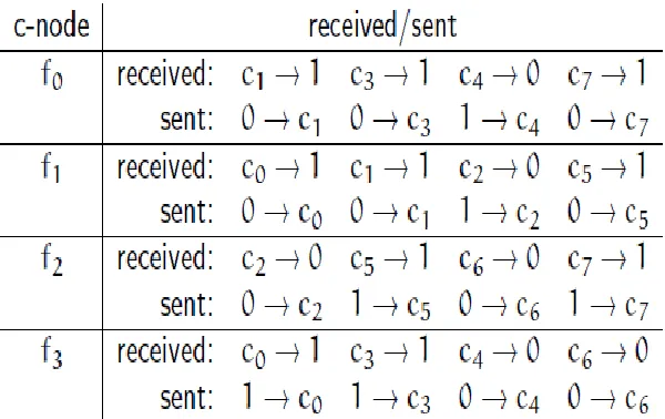
Table 1: overview over messages received and sent by the c-nodes in step 2 of the message passing algorithm
2. In the second step every check nodes fj calculate a response to every connected variable node. The response message contains the bit that fj believes to be the correct one for this v-node ci assuming that the other v-nodes connected to fj are correct. In other words: If you look at the example, every c-node fj is connected to 4 v-nodes. So a c-node fj looks at the message received from three v-nodes and calculates the bit that the fourth v-node should have in order to fulfill the parity check equation. Table 2 gives an overview about this step. Important is, that this might also be the point at which the decoding algorithm terminates. This will be the case if all check equations are fulfilled. We will later see that the whole algorithm contains a loop, so an other possibility to stop would be a threshold for the amount of loops.
© 2014, IJCSMC All Rights Reserved 883
4. Go to step 2. loop
In our example, the second execution of step 2 would terminate the decoding process since c1 has voted for 0 in the last step. This corrects the transmission error and all check equations are now satisfied.
2.2 Soft-decision decoding
The above description of hard-decision decoding was mainly for educational purpose to get an overview about the idea. Soft-decision decoding of LDPC codes, which is based on the concept of belief propagation, yields in a better decoding performance and is therefore belief the preferred method. The underlying idea is exactly the same as in propagation hard decision decoding. Before presenting the algorithm lets introduce some notations:
Pi = Pr(ci = 1|yi) (2)
• qij is a message sent by the variable node ci to the check node fj. Every message contains always the pair qij(0) and qij(1) which stands for the amount of belief that yi is a ‖0‖ or a ‖1‖. • rji is a message sent by the check node fj to the variable node ci. Again there is a rji(0) and rji(1) that indicates the (current) amount of believe in that yi is a ‖0‖ or a ‖1‖.
The step numbers in the following description correspond to the hard decision case.
© 2014, IJCSMC All Rights Reserved 884 2. The check nodes calculate their response messages rij2
So they calculate the probability that there is an even number of 1’s among the variable nodes except ci (this is exactly whatVj\i means). This probability is equal to the probability rji(0) that ci is a 0. This step and the information used to calculate the responses is illustrated in figure 2.
© 2014, IJCSMC All Rights Reserved 885
whereby the Konstants Kij are chosen in a way to ensure that qij(0)+qij(1) = 1. Ci\j now means all check nodes except fj. Again figure 2 illustrates the calculation in this step. At this point the v-nodes also update their current estimation of their variable ci. This is done by calculating the probabilities for 0 and 1 and voting for the bigger one. The used equations,
are quite similar to the ones to compute qij(b) but now the information from every c-node is used.
If the current estimated codeword fulfills now the parity check equations the algorithm terminates. Otherwise termination is ensured through a maximum number of iterations.
4. Go to step 2. loop
The explained soft decision decoding algorithm is a very simple variant, suited for BSC channels and could be modified for performance improvements. Beside performance issues there are numerical stability problems due to the many multiplications of probabilities. The results will come very close to zero for large block lengths. To prevent this, it is possible to change into the log-domain and doing additions instead of multiplications. The result is a more stable algorithm that even has performance advantages since additions are less costly.
3. ALGORITHM (MDD-BMP)
Modified DD-BMP (MDD-BMP) is a variant of the original algorithm in which only a single memory is assigned to each variable node, replacing the unique variable-to-check messages with a single global message. Hence the memory update function is
The variable node schematic for MDD-BMP is shown in Figure. 4. This simplification results in a loss in BER performance, though it also greatly reduces the complexity of the variable node. We demonstrate that in the case of MDD-BMP, the performance degradation is small, while the complexity reduction is significant, so using MDD-BMP in VLSI implementations is well justified. Furthermore, it allows the broadcasting concept to be applied to the variable-to-check messages.
© 2014, IJCSMC All Rights Reserved 886 Figure.4. MDD-BMP variable node schematic.
In this work, we present results for decoders based on both DD-BMP and MDD-BMP. At the system level, these architectures possess several merits that are useful in energy-efficient designs. The variable and check nodes are both simple, which translates to lower area and power consumption in VLSI chips. Furthermore, binary message exchange and broadcasting reduces wiring overhead. Since several successive messages opposing the value stored in a VN must be received before the sign of the VN changes, switching activity is also low [12]. Furthermore, DD-BMP is amenable to efficient highly parallel architectures. Unlike some recent fully node-parallel decoder architectures such as bit-serial min-sum [5] and pulse width min-sum [7], iterations in DD-BMP complete in a single clock cycle. As a result, DD-BMP tends to converge to a valid codeword rapidly, giving it a very high average throughput. Voltage and frequency scaling (VFS) can be applied, trading off throughput for reduced dynamic energy consumption.
4. MDD-BMP WITH OTHER LDPC CODES
© 2014, IJCSMC All Rights Reserved 887
Gallager bit-flipping decoding [22]. Additional analysis of the formation and dynamics of absorbing sets is performed in [23]. There have also been a number of implementation-oriented methods proposed for lowering the error floors of LDPC codes by overcoming or avoiding trapping sets. A prominent example is [10], which presents a hardware implementation of an OMS decoder for the (2048,1723) RS-LDPC code employing a post-processing decoding stage. This technique has proven highly effective at overcoming the dominant (8,8) absorbing set of this code, and thereby lowering the error floor. Another hardware implementation in [24] proposes an iterative decoding algorithm with backtracking, which attempts to collapse trapping sets by identifying participating bits and flipping them. The stochastic decoders in [25] and [26] can employ redecoding, which restarts decoding with a different random number generator seed—since these algorithms are probabilistic, decoding may thus take a different trajectory and avoid trapping sets that caused a previous attempt to fail. Similarly, in dithered belief
propagation, random processes are used in attempts to avoid or break out of trapping sets [27].
Likewise, early error floors and poor error correction performance are issues that must be solved for DB algorithms to be of practical use with general (non-FG) LDPC codes. In this work, we will focus on the (2048, 1723) RS-LDPC code, due to its importance to the IEEE 802.3an standard, the large body of prior work investigating its trapping sets, and its high popularity as an implementation target for highly-parallel decoder architectures.
Table 3
Wiring Complexity of The Implemented Decoders
Decoder Total wire length (m) Total interleaver wire length (m)
Interleaver wiring per edge (um)
DD-BMP 7920 3.586 772.69
MDD-BMP(273,191) 1793 0.337 72.53
REFERENCES
[1] D. J. Goodman, P. S. Henry, and V. K. Prabhu, ―Frequency-hopping multilevel FSK for mobile radio,‖ Bell Syst. Tech. J., vol. 59, no. 7, pp.1257–1275, Sep. 1980.
[2] Yue, ―Maximum Likelihood Combining for Noncoherent and Differentially Coherent Frequency-Hopping Multiple- Access Systems,‖ IEEE Trans. on Infom. Theory, vol. IT-28 , no. 4, pp. 631-639, 1982.
[3] U. Fiebig, ―Iterative Interference Cancellation for FFH/MFSK Systems,‖ IEE Proceedings
Communications, vol. 143 , No. 6, pp. 380-388, 1996.
[4] K. W. Halford and M. Brandt-Pearce, ―Multi-stage Multi-user Detection for FHMA,‖IEEE Trans. on
Commun., vol. 48, no. 9, Sept. 2000, pp. 1550-1562.
[5] A. Darabiha, A. C. Carusone, and F. Kschischang, ―Power reduction techniques for LDPC decoders,‖
IEEE J. Solid-State Circuits, vol. 43, no. 8, pp. 1835–1845, Aug. 2008.
[6] T. Brandon, R. Hang, and G. Block et al., ―A scalable LDPC decoder ASIC architecture with bit-serial message exchange,‖ Integr. VLSI J., vol. 41, no. 3, pp. 385–398, 2008.
© 2014, IJCSMC All Rights Reserved 888
[8] T. Mohsenin, D. Truong, and B. Baas, ―A low-complexity messagepassing algorithm for reduced routing congestion in LDPC decoders,‖ IEEE Trans. Circuits Syst. I, vol. 57, no. 5, pp. 1048–1061, May 2010.
[9] A. Darabiha, A. Carusone, and F. Kschischang, ―Block-interlaced LDPC decoders with reduced interconnect complexity,‖ IEEE Trans Circuits Syst. II, vol. 55, no. 1, pp. 74–78, Jan. 2008.
[10] Z. Zhang, V. Anantharam, M. J. Wainwright, and B. Nikolic, ―An efficient 10GBASE-T ethernet LDPC decoder design with low error floors,‖ IEEE J. Solid-State Circuits, vol. 45, no. 4, pp. 843–855, Apr.2010.
[11] M. Jiang, C. Zhao, Z. Shi, and Y. Chen, ―An improvement on the modified weighted bit flipping decoding algorithm for LDPC codes,‖ IEEE Commun. Lett., vol. 9, no. 9, pp. 814–816, Sep. 2005.
[12] N.Mobini, A. Banihashemi, and S. Hemati, ―A differential binarymessage-passing LDPC decoder,‖
IEEE Trans. Commun., vol. 57, no. 9, pp. 2518–2523, Sep. 2009.
[13] Y. Kou, S. Lin, and M. Fossorier, ―Low-density parity-check codes based on finite geometries: A rediscovery and new results,‖ IEEE Trans. Inf. Theory, vol. 47, no. 7, pp. 2711–2736, Nov. 2001.
[14] J. Cho, J. Kim, and W. Sung, ―VLSI implementation of a highthroughput soft-bit-flipping decoder for geometric LDPC codes,‖ IEEE Trans. Circuits Syst. I, vol. 57, no. 5, pp. 1083–1094, May 2010. [15] T. J. Richardson, ―Error-floors of LDPC codes,‖ in Proc. 41st Annu. Allerton Conf. Commun.,
Control, Comput., Oct. 2003, pp. 1426–1435.
[16] 10 Gigabit Ethernet: IEEE Standard for InformationTechnology- elecommunications and
Information Exchange Between Systems-Local and Metropolitan Area Networks-Specific Requirements Part 3: Carrier Sense Multiple Access With Collision Detection (CSMA/CD) Access Method and Physical
Layer Specifications, IEEE Standard 802.3an-2006, Aug. 2006 [Online]. Available: http://standards.
ieee.org/getieee802/download/802.3an-2006.pdf.
[17] I. Djurdjevic, J. Xu, K. Abdel-Ghaffar, and S. Lin, ―A class of lowdensity parity-check codes
constructed based on Reed-Solomon codes with two information symbols,‖ IEEE Commun. Lett., vol. 7,
no. 7, pp. 317–319, Jul. 2003.
[18] S. Hemati and A. Banihashemi, ―Dynamics and performance analysis of analog iterative decoding for low-density parity-check (LDPC) codes,‖ IEEE Trans. Commun., vol. 54, no. 1, pp. 61–70, 2006. [19] F. Kienle, N. Wehn, and H. Meyr, ―On complexity, energy-and implementation- efficiency of channel decoders,‖ IEEE Trans. Commun., vol. 59, no. 12, pp. 3301–3310, Dec. 2011.
[20] D. MacKay and M. Postol, ―Weaknesses of Margulis and Ramanujan-Margulis low-density parity-check codes,‖ Electron. Notes Theor. Comp. Sci., vol. 74, pp. 97–104, Oct. 2003.
[21] C. Di, D. Proietti, I. Telatar, T. Richardson, and R. Urbanke, ―Finitelength analysis of low-density parity-check codes on the binary erasure channel,‖ IEEE Trans. Inf. Theory, vol. 48, no. 6, pp. 1570– 1579, Jun. 2002.
[22] L. Dolecek, Z. Zhang, V. Anantharam,M.Wainwright, and B. Nikolic,―Analysis of absorbing sets and fully absorbing sets of array-based LDPC codes,‖ IEEE Trans. Inf. Theory, vol. 56, no. 1, pp. 181– 201, Jan. 2010.
[23] C. Schlegel and S. Zhang, ―On the dynamics of the error floor behavior in (regular) LDPC codes,‖
IEEE Trans. Inf. Theory, vol. 56, no. 7, pp. 3248–3264, Jul. 2010.
[24] F. Leduc-Primeau, S. Hemati, S. Mannor, and W. J. Gross, ―Dithered belief propagation decoding,‖
IEEE Trans. Commun., vol. 60, no. 8, pp. 2042–2047, Aug. 2012.
[25] Y. Han and W. Ryan, ―Low-floor decoders for LDPC codes,‖ IEEE Trans. Commun., vol. 57, no. 6,
pp. 1663–1673, Jun. 2009.
[26] M. Ardakani and F. Kschischang, ―Gear-shift decoding,‖ IEEE Trans. Commun., vol. 54, no. 7, pp. 1235–1242, Jul. 2006.