A DSP BASED STUDY OF PATTERN NULLING AND PATTERN SHAPING USING TRANSFORM DOMAIN WINDOW TECHNIQUE
Q. M. Alfred and K. Bishayee
Department of Electronics & Communication Engineering University Institute of Technology
Burdwan, West Bengal, India
T. Chakravarty
Embedded Systems Innovation Laboratory Tata Consultancy Services
Abhilash, Bangalore, India
S. K. Sanyal
Department of Electronics & Telecommunication Engineering Jadavpur University
Kolkata, India
Abstract—This article aims to provide a novel and efficient technique for pattern shaping and null steering in the environment of unwanted interferences. This paper presents a DSP based method, where at first DFT coefficients are obtained from spatial domain sampling and then operating by suitable window function gives new set of DFT coefficients. IFFT(IDFT) over these coefficients provide complex weights which adaptively introduces null in the direction interference while keeping the main beam toward desired signal.
1. INTRODUCTION
has some priori knowledge, then it is possible to provide null in that direction(s). Various research works in this area has been performed. Several adaptive and null steering methods (algorithms) are discussed in [1–20]. Among them some uses phase control methods [1–4], where only phase of the elements are adjusted properly to provide beam steering and simultaneously imposing null in interference direction. Some paper deals with pattern nulling by only amplitude control [5, 6]. All these method have their own advantages and disadvantages in terms of complexity, cost, bandwidth etc. These methods are suitable for interference cancellation but can not simultaneously provide different shaped patterns. In [7], a simple wideband subarray technique for simultaneous pattern shaping and pattern nulling is proposed. But with the advent of high speed digital signal processor, DSP based beam forming (beam shaping, pattern nulling, beam steering etc.) algorithms are now emerging trends. Wu et al. [8] have studied an interesting algorithm for pattern synthesis, where DFT and IDFT is adopted for different beam pattern realization.
In this communication authors have also proposed a DSP based novel technique for adaptively interference rejection and pattern shaping. Instead of using conventional time domain window [8], here it is proposed a novel transform domain (space domain) window for adaptive beamforming (pattern nulling, shaping etc.)
2. THEORETICAL OVERVIEW
In this paper a linear array of isotropic radiating elements (K+ 1 nos.) having inter-element spacing of ‘d’ have been considered. Taking phase of the first element as reference, resultant antenna pattern in spatial domain can be represented by the following:
S(θ) = K
n=0
Wn·exp
−j·2π
λ ·n·d·cos(θ)
(1)
where,Wnaccounts for the weight assigned to thenth antenna element, λis the wavelength and θ is the angle of arrival measured relative to array normal. Without loss of generality and to avoid grating lobe problem d=λ/2 is considered.
Now ϕ can be chosen as a variable so that, ϕ = πcos (θ), then ϕ∈[−π,+π] and the Eq. (1) reduces to the following.
S(ϕ) = K
n=0
Here in the expression ofS(ϕ), the inner terms of [exp (−j·n·ϕ)]n=0,... ,K can be obtained as:
+π
−π
exp(−j·n·ϕ) exp(j·m·ϕ)dx=
2π, m=n 0, m=n
(3)
Equation (3) shows that [exp (−j·n·ϕ)]n=0,... ,K from an orthogonal set withinϕ∈[−π,+π].
Hence from the well known property of orthogonality, the weights (coefficients) of expression (Eq. (2)) can be calculated as follows:
Wn= 1 2π
+π
−π
S(ϕ) exp (j·n·ϕ)dx n= 0,1, . . . , K (4)
Here in this proposition, we have deliberately selected Wn = 1(for uniform array) and then Eq. (2) is reduced by the following.
S(ϕ) = K
n=0
exp (−j·n·ϕ) (5) Here actually, S(ϕ) is space-domain Fourier Transform of radiation strength. Literally, it can be considered as Discrete Space Fourier transform (DSFT) analogous to its time domain counterpart, discrete-time Fourier transform (DTFT).
Now, asS(ϕ) is continuous in the space domain, it is then sampled by N nos. of discrete samples for computational effectiveness, can be found by modifying Eq. (5), is given below .
S(k) =S(ϕ)ϕ=2π Nk=
K
n=0 exp
−j2π N ·k·n
, where 0≤k≤N−1 (6) Equation (6) actually provides the DFT (Discrete Fourier Transform) of the quiescent pattern of the linear array. These DFT coefficients or S(k) of the quiescent pattern are operated (e.g., multiplied) by some transform domain windows to generate a new set of DFT coefficientsS(k). Now IDFT (IFFT) is performed over these modified set, which in turn yields the complex array weights s(n) and these weights are fed to the antenna elements to generate desired pattern, shown in Eq. (7).
s(n) = 1 N
N−1
k=0
S/(k) exp
+j2π N ·k·n
Application of these modified weights s(n) to each radiating element will generate the adapted array pattern, as given by the following expression:
Sa(ϕ) = K
n=0
s(n)·exp (−j·ϕ·n) (8)
where Sa(ϕ), stands for adaptive array pattern. Hence the Eq. (8) is also a DSFT operation on the linear discrete array elements. These patterns are adaptive to avoid undesired interference and they also can be employed to some special purposes which are detailed in the following section.
3. SPATIAL WINDOW TECHNIQUE
Here the term ‘window’ signifies a suitably chosen matrix of real coefficients, operates over the DFT coefficients to modify quiescent pattern in desirable way.
These windows are operated in spatial domain for various pattern shaping purposes, can be highlighted by the following.
a) Rejection of unwanted interference(s) by adaptively imposing null(s) at the direction of interference arrival.
b) Pattern shaping in the environment of interference or generation of special purpose patterns like sector beam, cosecant beams etc. Schematically, this procedure can be described as follows.
Realization of this method with the help of Matlab simulation is detailed in the following section.
4. PATTERN NULLING AND RESULTS
10) uniform isotropic antenna elements has been considered for all the situations discussed here.
Case-1 (single interference):
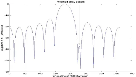
Let us consider a situation, where a single source of interference is arriving towards ϕ= 0.27π (corresponding to 228th sample point) in the quiescent pattern as shown in Fig. 1.
To reduce the effect of interference, a pattern null to be imposed at the direction of interference arrival.
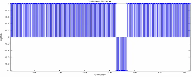
Figure 1. Quiescent pattern with a single interference atϕ= 0.27π. Under this null constraint, the quiescent pattern is adapted by the window technique. Here a windoww(k) is of equal size of DFT samples (N = 360) is selected, where first 213 samples having magnitude +1, next 21 samples are −1 and last 126 samples are +1, as depicted in Fig. 2.
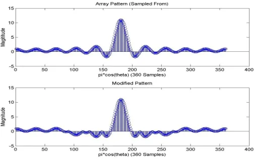
After multiplication by this window to the original DFT coefficients S(k), the nearest sidelobe region (RHS from broadside) is suppressed toward negative. Original DFT pattern (array pattern) and its adapted form (modified pattern) after windowing are depicted in Fig. 3.
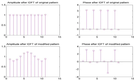
After multiplication, a new set of DFT coefficient is hereby produced S/(k). Now IDFT is performed over S/(k), which yields a set of complex array coefficients s/(n). Amplitude and phase plot
Figure 3. Original DFT pattern (array pattern) and its adapted form (modified pattern).
of thiss/(n) is comparatively(w.r.t original array excitation) shown in Fig. 4.
Now the coefficients,s/(n) is fed to the array elements as complex weight vector , which produces the adapted null in the desired direction is shown in Fig. 4.
It is worthwhile to mention that, taking DSFT operation over these s/(n) coefficient produces adapted pattern(in Fig. 5).
Figure 5. Adapted pattern in the interference direction.
Case – 2 (double interference):
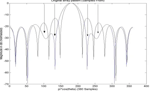
Consider another situation, where two interferences are arriving from different direction shown (indicated by two arrows) in Fig. 6. Interferences are impinging on quiescent pattern on both the sidelobes at the angles ϕ = 0.73π and ϕ = −0.27π (132nd and 228th sample points) respectively.
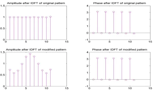
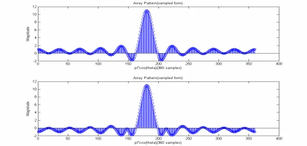
Similarly, original DFT pattern S(k) and adapted pattern S/(k) (after multiplication with proper window) is as shown in Fig. 7.
Figure 7. Original DFT coefficient (array pattern) and its adapted form (modified pattern).
Figure 8 depicts amplitude and phase plot of resultant complex coefficients/(n) after performing IDFT.
Figure 8. Comparative (w.r.t original array excitation) amplitude and phase plot of s/(n).
Figure 9. Adapted pattern in the interference direction.
Case – 3 (multiple interference):
This procedure can be applied to reduce the effect multiple interferences by choosing appropriate window. It is assumed here that the interferences coming along various direction, they are at ϕ= 0.55π, ϕ= 0.73π, ϕ=−0.27π &ϕ=−0.45π.
Figure 10 shows the quiescent and adapted DFT coefficient before and after windowing respectively. Fig. 11 gives amplitude and phase plots of the complex weights. Fig. 12 shows the resultant pattern imposed over quiescent pattern.
Figure 11. Amplitude and phase plot of the complex weights.
Figure 12. Adapted pattern in the environment multiple interference. (Both the quiescent and adapted beams are superimposed on each other).
5. PATTERN SHAPING AND RESULTS
This may also proved to be an efficient technique for special purpose pattern generation. For example, Low-sidelobe sum pattern, sector pattern, cosecant pattern etc. They are needed for some special purposes in aviation, wireless communication etc.
representative shaped patterns is briefly discussed.
Low-sidelobe sum pattern:
Low sidelobe sum pattern is widely used in search radars. To generate such pattern, transform domain window w(k) is chosen in such a way, that after multiplication with original DFT coefficients S(k), all the side lobes except the main lobe produces negative lobes.
In Fig. 13 DFT samples of the quiescent pattern and its windowed DFT coefficient are shown.
Figure 13. Original DFT coefficient and its adapted form (modified pattern).
Figure 14 depicts the resultant sum pattern with suppress sidelobe levels.
Figure 15. Original DFT coefficient and its adapted form (modified pattern) after applying Ist window (w/(k)).
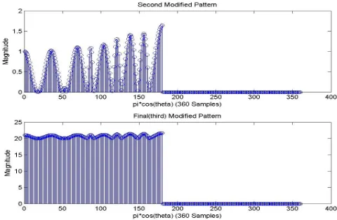
Figure 16. Original DFT coefficient and its adapted form (modified pattern) after applying 2nd (w//(k)) and 3rd window (w///(k)) respectively.
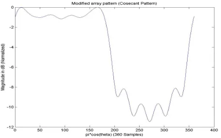
Cosecant-type Pattern Generation:
Another special purpose pattern is cosecant pattern, which is essential in air-traffic surveillance.
Figure 17. Amplitude and phase plot of the complex weights for cosecant type pattern generation.
Figure 18. Generated Cosecant type pattern.
arew(k),w/(k) andw//(k) respectively, can be shown by following. S/(k) =w//(w/(w(S(k)))) (9) Firstly, the window w(k) is multiplied with original DFT coefficients S(k), then all the negative coefficient becomes positive (Fig. 15). Then after multiplication with second window w(k), right half portion of the pattern is forced to zero value (Fig. 16). Finally, the third window w(k) is used to raise the magnitude of the coefficients (Fig. 16).
phase plot of the complex coefficient for original pattern and the shaped pattern can be shown as below (Fig. 17).
Figure 18 indicates the generated shaped pattern using the complex IDFT coefficients.
6. CONCLUSIONS
This paper premises the method of pattern nulling and pattern shaping using spatial (transform) domain window technique, which is simple than the time domain counterpart. Here in the course of computation, Matlabsimulation is effectively exploited for spatial domain sampling or to get DFT coefficients. Inverse Fast Fourier Transform (IFFT) is adopted for faster results than normal IDFT.
REFERENCES
1. Baird, D. and G. Rassweiler, “Adaptive sidelobe nulling using digitally controlled phase shifters,”IEEE Trans. on Antennas and Propagation, Vol. 24, No. 5, 638–649, Sept. 1976.
2. Steyskal, H., “Simple method for pattern nulling by phase perturbation,” IEEE Trans. on Antennas and Propagation, Vol. 31, 163–166, 1983.
3. Haupt, R. L., “Phase-only adaptive nulling with a genetic algorithm,”IEEE Trans. on Antennas Propagation, Vol. 45, 1009– 1015, 1997.
4. Vescovo, R., “Null synthesis by phase control for antenna arrays,”
Electronics Letters, Vol. 36, No. 33, Feb. 2000.
5. Vu, T. B., “Method of null steering without using phase-shifters,”
Proc. Inst. Elect. Eng., Vol. 131, Pt. H, 242–246, Aug. 1984. 6. Vu, T. B., “Null steering by controlling current amplitudes only,”
IEEE Antennas Propagat. SOC. Int. Symp. Dig., 811–814, 1984. 7. Alfred, Q. M., T. Chakravarty, G. Singh, and S. K. Sanyal, “A
novel wideband subarray technique for shaped pattern generation and adaptively interference rejection,”Int. Journal of Infrared and Millimeter Waves, Vol. 29, No. 3, March 2008.
8. Wu, W.-C. and Y. J. Wang, “A study of beam pattern generation methods for antenna array system,” Journal of Science and Engineering Technology, Vol. 1, No. 2, 7–12, March 2005.
10. Mismar, M. J. and T. H. Ismail, “Pattern nulling by iterative
phase perturbation,” Progress In Electromagnetics Research,
PIER 22, 181–195, 1999.
11. Ismail, T. H., M. J. Mismar, and M. M. Dawoud, “Linear array pattern synthesis for wide band sector nulling,” Progress In Electromagnetics Research, PIER 21, 91–101, 1999.
12. Chung, Y. C. and R. L. Haupt, “Amplitude and phase adaptive nulling with a genetic algorithm,” J. Electromagnetic Waves and Applications, Vol. 14, 631–649, 2000.
13. Mouhamadou, M., P. Vaudon, and M. Rammal, “Smart
antenna array patterns synthesis: Null steering and multi-user
beamforming by phase control,” Progress In Electromagnetics
Research, PIER 60, 95–106, 2006.
14. Mouhamadou, M., P. Armand, P. Vaudon, and M. Rammal, “In-terference suppression of the linear antenna arrays controlled by phase with use of SQP algorithm,” Progress In Electromagnetics Research, PIER 59, 251–265, 2006.
15. Mitilineos, S. A., S. C. A. Thomopoulos, and C. N. Capsalis, “Genetic design of dual-band, switched-beam dipole arrays, with elements failure correction, retaining constant excitation coefficients,”J. Electromagnetic Waves and Applications, Vol. 20, 1925–1942, 2006.
16. Mahanti, G. K., A. Chakraborty, and S. Das, “Design of fully digital controlled reconfigurable array antennas with fixed dynamic rage ratio,”J. Electromagnetic Waves and Applications, Vol. 21, 97–106, 2007.
17. Lee, K. C. and J. Y. Jhang, “Application of particle swarm algorithm to the optimization of unequally spaced antenna arrays,” J. Electromagnetic Waves and Applications, Vol. 20, 2001–2012, 2006.
18. Akdagli, A. and K. Guney, “A clonal selection algorithm for null synthesizing of linear antenna arrays by amplitude control,”
J. Electromagnetic Waves and Applications, Vol. 20, 1007–1020, 2006.
19. Akdagli, A., K. Guney, and B. Babayigit, “Clonal selection algorithm for design of reconfigurable antenna array with discrete
phase shifters,” J. Electromagnetic Waves and Applications,
Vol. 21, 215–227, 2007.
20. Hosseini, S. A. and Z. Atlasbaf, “Optimization of side lobe level and fixing Quasi-nulls in both of the sum and difference patterns by using continuous ant colony optimization (ACO) method,”